Page 183 of 3189
![NISSAN ALMERA N16 2003 Electronic Repair Manual SERVICE DATA AND SPECIFICATIONS (SDS)
EM-105
[QG]
C
D
E
F
G
H
I
J
K
L
MA
EM
Intake valve timing control solenoid valve
6.3 - 8.3 (0.64 - 0.85, 56 - 73)*2
Camshaft position sensor (PHASE)
7.2 - 10.8 (0 NISSAN ALMERA N16 2003 Electronic Repair Manual SERVICE DATA AND SPECIFICATIONS (SDS)
EM-105
[QG]
C
D
E
F
G
H
I
J
K
L
MA
EM
Intake valve timing control solenoid valve
6.3 - 8.3 (0.64 - 0.85, 56 - 73)*2
Camshaft position sensor (PHASE)
7.2 - 10.8 (0](/manual-img/5/57350/w960_57350-182.png)
SERVICE DATA AND SPECIFICATIONS (SDS)
EM-105
[QG]
C
D
E
F
G
H
I
J
K
L
MA
EM
Intake valve timing control solenoid valve
6.3 - 8.3 (0.64 - 0.85, 56 - 73)*2
Camshaft position sensor (PHASE)
7.2 - 10.8 (0.73 - 1.1, 64 - 95) *2
Camshaft sprocket (INT) 78.4 - 88.2 (8.0 - 9.0, 58 - 65)
Camshaft sprocket (EXH) 98.1 - 127.5 (10.0 - 13.0, 73 - 94)
*1 Camshaft bracket 1)
2.0 (0.2, 18) *
2
2)
5.9 (0.6, 52) *2
3)
9.0 - 11.8 (0.92 - 1.20, 80 - 104)*2
Crankshaft pulley132.4 - 152.0 (14.0 - 15.0, 98 - 112)
Front cover
6.92 - 9.51 (0.71 - 0.97, 62 - 84)*
2
Timing chain tension guide 15.7 - 20.6 (1.6 - 2.1, 12 - 15)
*1 Cylinder head 1) 29.4 (3.0, 22)
2) 58.8 (6.0, 43)
3) 0 (0.0, 0)
4) 27.4 - 31.4 (2.8 - 3.2, 21 - 23)
5) 50° - 55° (Angle tightening)
Cylinder head front cover
6.92 - 9.5 (0.71 - 0.96, 62 - 84)*
2
Flywheel (M/T)83.4 - 93.2 (8.5 - 9.5, 62 - 68)
Drive plate (A/T)93.2 - 103 (9.5 - 10.5, 69 - 75)
*1 Connecting rod bearing cap 1) 13.72 - 15.68 (1.4 - 1.5, 10.2 - 11 . 5 )
2) 35° - 40° (Angle tightening)
Knock sensor15.7 - 20.6 (1.6 - 2.1, 12 - 15)
Crankshaft position sensor (POS)
7.2 - 10.8 (0.8 - 1.1, 64 - 95)*
2
Rear oil seal retainer
6.3 - 8.3 (0.65 - 0.84, 56 - 73)*2
Signal plate
7.6 - 9.2 (0.78 - 0.93, 68 - 81)*2
Page 192 of 3189
NJEM0051
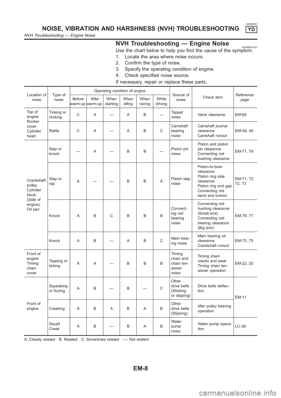
NVH Troubleshooting — Engine NoiseNJEM0051S01Use the chart below to help you find the cause of the symptom.
1. Locate the area where noise occurs.
2. Confirm the type of noise.
3. Specify the operating condition of engine.
4. Check specified noise source.
If necessary, repair or replace these parts.
Location of
noiseTy p e o f
noiseOperating condition of engine
Source of
noiseCheck itemReference
page Before
warm-upAfter
warm-upWhen
startingWhen
idlingWhen
racingWhile
driving
To p o f
engine
Rocker
cover
Cylinder
headTicking or
clickingC A—A B—Tappet
noiseValve clearance EM-60
Rattle C A — A B CCamshaft
bearing
noiseCamshaft journal
clearance
Camshaft runoutEM-49, 49
Crankshaft
pulley
Cylinder
block
(Side of
engine)
Oil panSlap or
knock—A—B B—Piston pin
noisePiston and piston
pin clearance
Connecting rod
bushing clearanceEM-71, 79
Slap or
rapA——B B APiston slap
noisePiston-to-bore
clearance
Piston ring side
clearance
Piston ring end gap
Connecting rod
bend and torsionEM-71, 72,
72, 73
Knock A B C B B BConnect-
ing rod
bearing
noiseConnecting rod
bushing clearance
(Small end)
Connecting rod
bearing clearance
(Big end)EM-79, 77
Knock A B — A B CMain bear-
ing noiseMain bearing oil
clearance
Crankshaft runoutEM-75, 75
Front of
engine
Timing
chain
coverTapping or
tickingAA—BBBTiming
chain and
chain ten-
sioner
noiseTiming chain
cracks and wear
Timing chain ten-
sioner operationEM-22, 20
Front of
engineSqueaking
or fizzingA B—B—COther
drive belts
(Sticking
or slipping)Drive belts deflec-
tion
EM-11
CreakingABABABOther
drive belts
(Slipping)Idler pulley bearing
operation
Squall
CreakAB—BABWater
pump
noiseWater pump opera-
tionLC-39
A: Closely related B: Related C: Sometimes related —: Not related
NOISE, VIBRATION AND HARSHNESS (NVH) TROUBLESHOOTINGYD
NVH Troubleshooting — Engine Noise
EM-8
Page 196 of 3189
If the belt deflection of the current belt is out of the “Limit
for re-tightening”, adjust to the “Adjusted value”.
When checking belt deflection immediately after
installation, first adjust it to the specified value. Then,
after turning crankshaft two turns or more, re-adjust it to
the specified value to avoid variation in deflection
between pulleys.
Make sure the belts are fully fitted into the pulley grooves
during installation.
Handle with care to avoid smearing the belts with oil or
cooling water etc.
Do not twist or bend the belts with strong force.
JEM251G
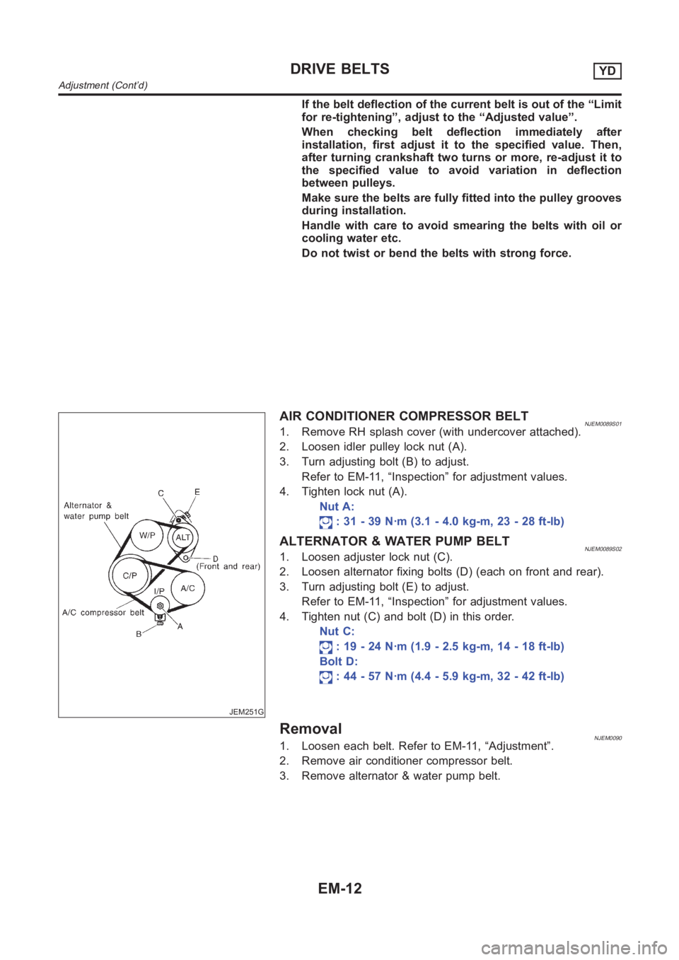
AIR CONDITIONER COMPRESSOR BELTNJEM0089S011. Remove RH splash cover (with undercover attached).
2. Loosen idler pulley lock nut (A).
3. Turn adjusting bolt (B) to adjust.
Refer to EM-11, “Inspection” for adjustment values.
4. Tighten lock nut (A).
Nut A:
: 31 - 39 N·m (3.1 - 4.0 kg-m, 23 - 28 ft-lb)
ALTERNATOR & WATER PUMP BELTNJEM0089S021. Loosen adjuster lock nut (C).
2. Loosen alternator fixing bolts (D) (each on front and rear).
3. Turn adjusting bolt (E) to adjust.
Refer to EM-11, “Inspection” for adjustment values.
4. Tighten nut (C) and bolt (D) in this order.
Nut C:
: 19 - 24 N·m (1.9 - 2.5 kg-m, 14 - 18 ft-lb)
Bolt D:
: 44 - 57 N·m (4.4 - 5.9 kg-m, 32 - 42 ft-lb)
RemovalNJEM00901. Loosen each belt. Refer to EM-11, “Adjustment”.
2. Remove air conditioner compressor belt.
3. Remove alternator & water pump belt.
DRIVE BELTSYD
Adjustment (Cont’d)
EM-12
Page 200 of 3189
JEM114G
3. Remove air compressor bracket.
4. Remove lower oil pan bolts.
Loosen bolts in the reverse order of that shown in the figure.
SEM544G
5. Remove lower oil pan.
a. Insert Tool between upper oil pan and lower oil pan.
Be careful not to damage aluminum mating surface.
Do not insert screwdriver, or oil pan flange will be
deformed.
SEM545G
b. Slide Tool by tapping on the side of the Tool with a hammer.
c. Remove lower oil pan.
6. Remove oil strainer.
7. Remove front exhaust tube and its support.
Refer to FE-26, “Removal and Installation”.
JEM553G
8. Set a suitable transmission jack under transaxle and hoist
engine with engine slinger.
Place the jack as close to the center as possible for support.
9. Remove front and rear engine mounting nuts and bolts.
10. Remove center member.
11. Remove crankshaft position sensor (TDC sensor) from oil pan.
12. Remove oil pan cover.
OIL PANYD
Removal (Cont’d)
EM-16
Page 201 of 3189
JEM116G
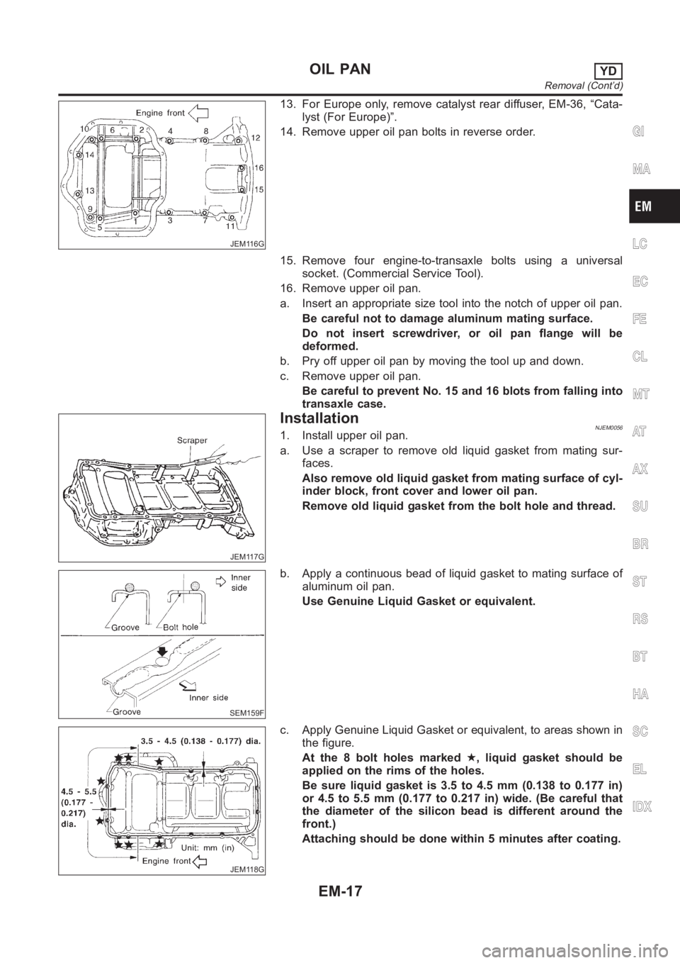
13. For Europe only, remove catalyst rear diffuser, EM-36, “Cata-
lyst (For Europe)”.
14. Remove upper oil pan bolts in reverse order.
15. Remove four engine-to-transaxle bolts using a universal
socket. (Commercial Service Tool).
16. Remove upper oil pan.
a. Insert an appropriate size tool into the notch of upper oil pan.
Be careful not to damage aluminum mating surface.
Do not insert screwdriver, or oil pan flange will be
deformed.
b. Pry off upper oil pan by moving the tool up and down.
c. Remove upper oil pan.
Be careful to prevent No. 15 and 16 blots from falling into
transaxle case.
JEM117G
InstallationNJEM00561. Install upper oil pan.
a. Use a scraper to remove old liquid gasket from mating sur-
faces.
Also remove old liquid gasket from mating surface of cyl-
inder block, front cover and lower oil pan.
Remove old liquid gasket from the bolt hole and thread.
SEM159F
b. Apply a continuous bead of liquid gasket to mating surface of
aluminum oil pan.
Use Genuine Liquid Gasket or equivalent.
JEM118G
c. Apply Genuine Liquid Gasket or equivalent, to areas shown in
the figure.
At the 8 bolt holes marked★, liquid gasket should be
applied on the rims of the holes.
Be sure liquid gasket is 3.5 to 4.5 mm (0.138 to 0.177 in)
or 4.5 to 5.5 mm (0.177 to 0.217 in) wide. (Be careful that
the diameter of the silicon bead is different around the
front.)
Attaching should be done within 5 minutes after coating.
GI
MA
LC
EC
FE
CL
MT
AT
AX
SU
BR
ST
RS
BT
HA
SC
EL
IDX
OIL PANYD
Removal (Cont’d)
EM-17
Page 202 of 3189
JEM116G
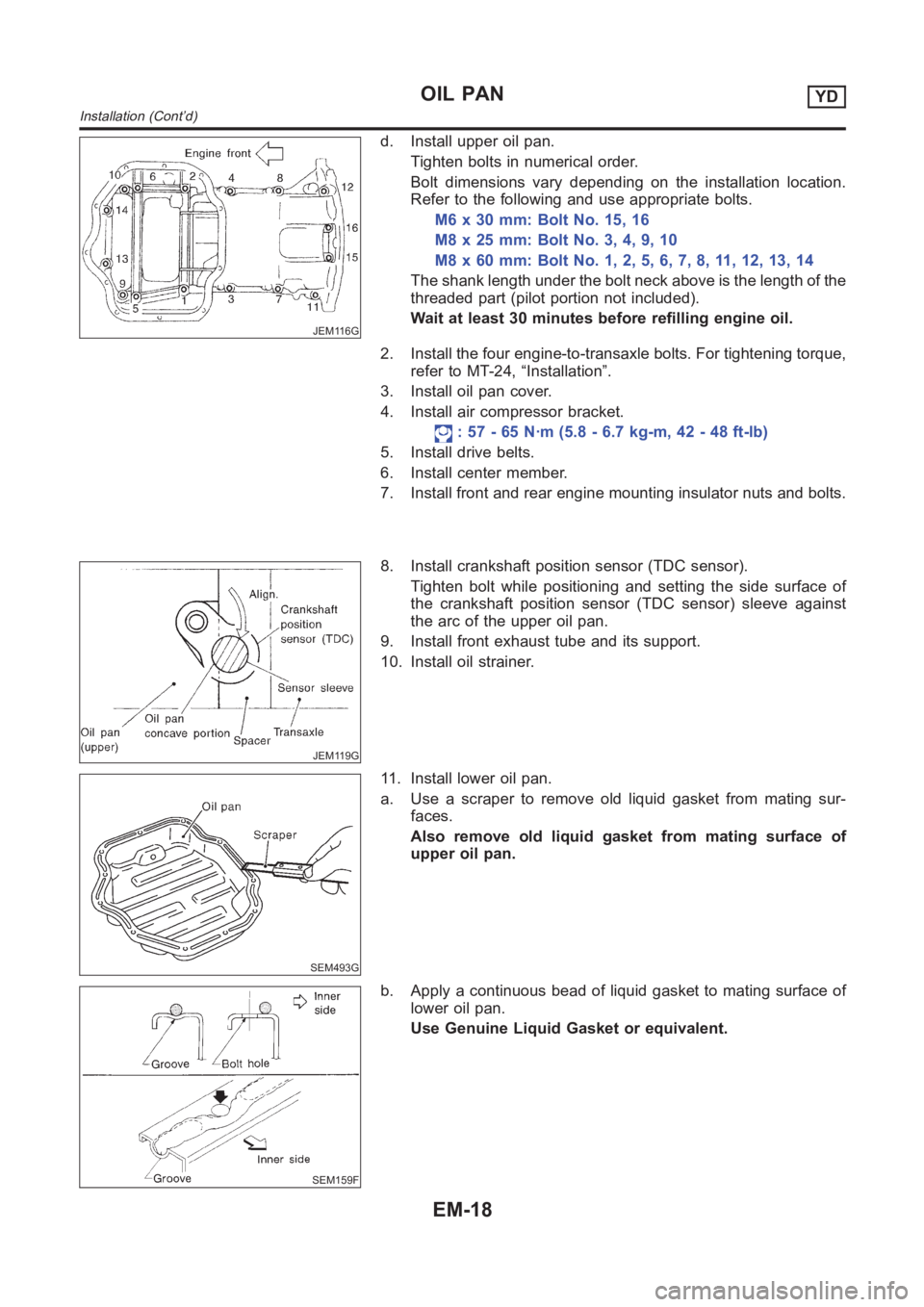
d. Install upper oil pan.
Tighten bolts in numerical order.
Bolt dimensions vary depending on the installation location.
Refer to the following and use appropriate bolts.
M6 x 30 mm: Bolt No. 15, 16
M8x25mm:BoltNo.3,4,9,10
M8x60mm:BoltNo.1,2,5,6,7,8,11,12,13,14
The shank length under the bolt neck above is the length of the
threaded part (pilot portion not included).
Wait at least 30 minutes before refilling engine oil.
2. Install the four engine-to-transaxle bolts. For tightening torque,
refer to MT-24, “Installation”.
3. Install oil pan cover.
4. Install air compressor bracket.
: 57 - 65 N·m (5.8 - 6.7 kg-m, 42 - 48 ft-lb)
5. Install drive belts.
6. Install center member.
7. Install front and rear engine mounting insulator nuts and bolts.
JEM119G
8. Install crankshaft position sensor (TDC sensor).
Tighten bolt while positioning and setting the side surface of
the crankshaft position sensor (TDC sensor) sleeve against
the arc of the upper oil pan.
9. Install front exhaust tube and its support.
10. Install oil strainer.
SEM493G
11. Install lower oil pan.
a. Use a scraper to remove old liquid gasket from mating sur-
faces.
Also remove old liquid gasket from mating surface of
upper oil pan.
SEM159F
b. Apply a continuous bead of liquid gasket to mating surface of
lower oil pan.
Use Genuine Liquid Gasket or equivalent.
OIL PANYD
Installation (Cont’d)
EM-18
Page 205 of 3189
JEM121G
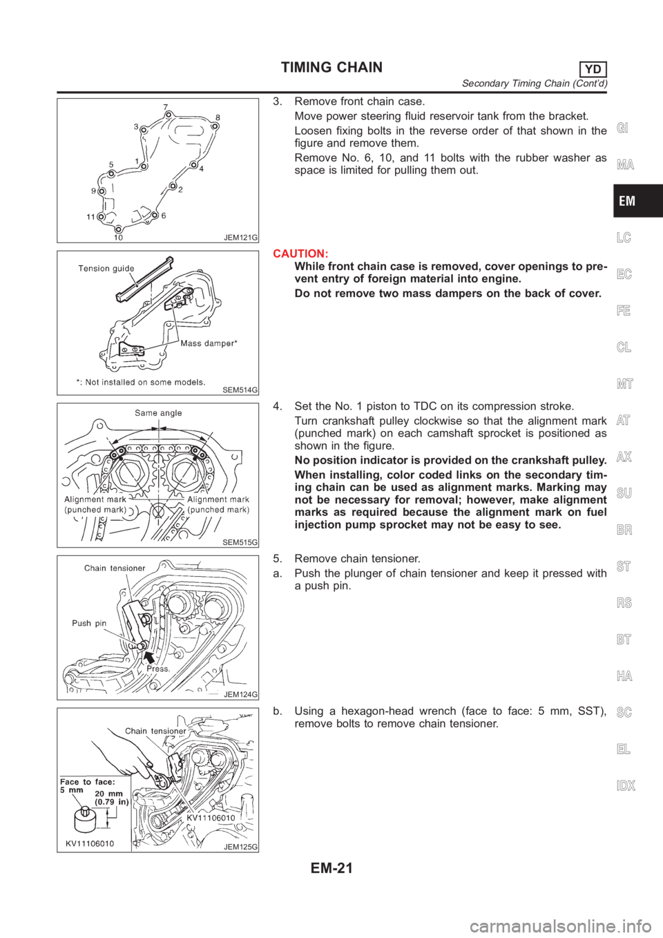
3. Remove front chain case.
Move power steering fluid reservoir tank from the bracket.
Loosen fixing bolts in the reverse order of that shown in the
figure and remove them.
Remove No. 6, 10, and 11 bolts with the rubber washer as
space is limited for pulling them out.
SEM514G
CAUTION:
While front chain case is removed, cover openings to pre-
vent entry of foreign material into engine.
Do not remove two mass dampers on the back of cover.
SEM515G
4. Set the No. 1 piston to TDC on its compression stroke.
Turn crankshaft pulley clockwise so that the alignment mark
(punched mark) on each camshaft sprocket is positioned as
shown in the figure.
No position indicator is provided on the crankshaft pulley.
When installing, color coded links on the secondary tim-
ing chain can be used as alignment marks. Marking may
not be necessary for removal; however, make alignment
marks as required because the alignment mark on fuel
injection pump sprocket may not be easy to see.
JEM124G
5. Remove chain tensioner.
a. Push the plunger of chain tensioner and keep it pressed with
a push pin.
JEM125G
b. Using a hexagon-head wrench (face to face: 5 mm, SST),
remove bolts to remove chain tensioner.
GI
MA
LC
EC
FE
CL
MT
AT
AX
SU
BR
ST
RS
BT
HA
SC
EL
IDX
TIMING CHAINYD
Secondary Timing Chain (Cont’d)
EM-21
Page 207 of 3189
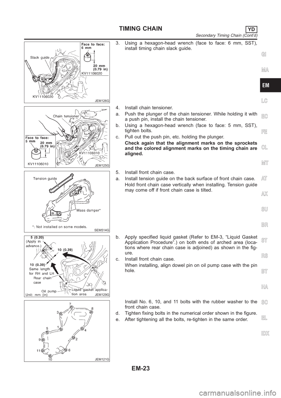
JEM126G
3. Using a hexagon-head wrench (face to face: 6 mm, SST),
install timing chain slack guide.
JEM125G
4. Install chain tensioner.
a. Push the plunger of the chain tensioner. While holding it with
a push pin, install the chain tensioner.
b. Using a hexagon-head wrench (face to face: 5 mm, SST),
tighten bolts.
c. Pull out the push pin, etc. holding the plunger.
Check again that the alignment marks on the sprockets
and the colored alignment marks on the timing chain are
aligned.
SEM514G
5. Install front chain case.
a. Install tension guide on the back surface of front chain case.
Hold front chain case vertically when installing. Tension guide
may come off if front chain case is tilted.
JEM129G
b. Apply specified liquid gasket (Refer to EM-3, “Liquid Gasket
Application Procedure”.) on both ends of arched area (loca-
tions where rear chain case is adjoined) as shown in the fig-
ure.
c. Install front chain case.
When installing, align dowel pin on oil pump case with the pin
hole.
JEM121G
Install No. 6, 10, and 11 bolts with the rubber washer to the
front chain case.
d. Tighten fixing bolts in the numerical order shown in the figure.
e. After tightening all the bolts, re-tighten in the same order.
GI
MA
LC
EC
FE
CL
MT
AT
AX
SU
BR
ST
RS
BT
HA
SC
EL
IDX
TIMING CHAINYD
Secondary Timing Chain (Cont’d)
EM-23