2003 NISSAN ALMERA N16 Front
[x] Cancel search: FrontPage 210 of 3189
REMOVALNJEM0094S011. Remove engine and transaxle assembly. Refer to EM-63,
“ENGINE ASSEMBLY”.
2. Remove transaxle from engine. Place engine onto engine
stand (SST). Refer to EM-67, “CYLINDER BLOCK”, “Disas-
sembly”.
3. Remove the following parts:
Oil pan (upper and lower)
Refer to EM-15, “OIL PAN”.
Oil filter bracket
Refer to LC-31, “Oil Filter Bracket”.
Injection tube
Refer to EC-21, “Injection Tube and Injection Nozzle”.
4. Remove secondary timing chain and associated parts.
Refer to EM-20, “Secondary Timing Chain”.
5. When removing rear chain case, remove camshaft sprockets.
Refer to EM-46, “CAMSHAFT”.
JEM131G
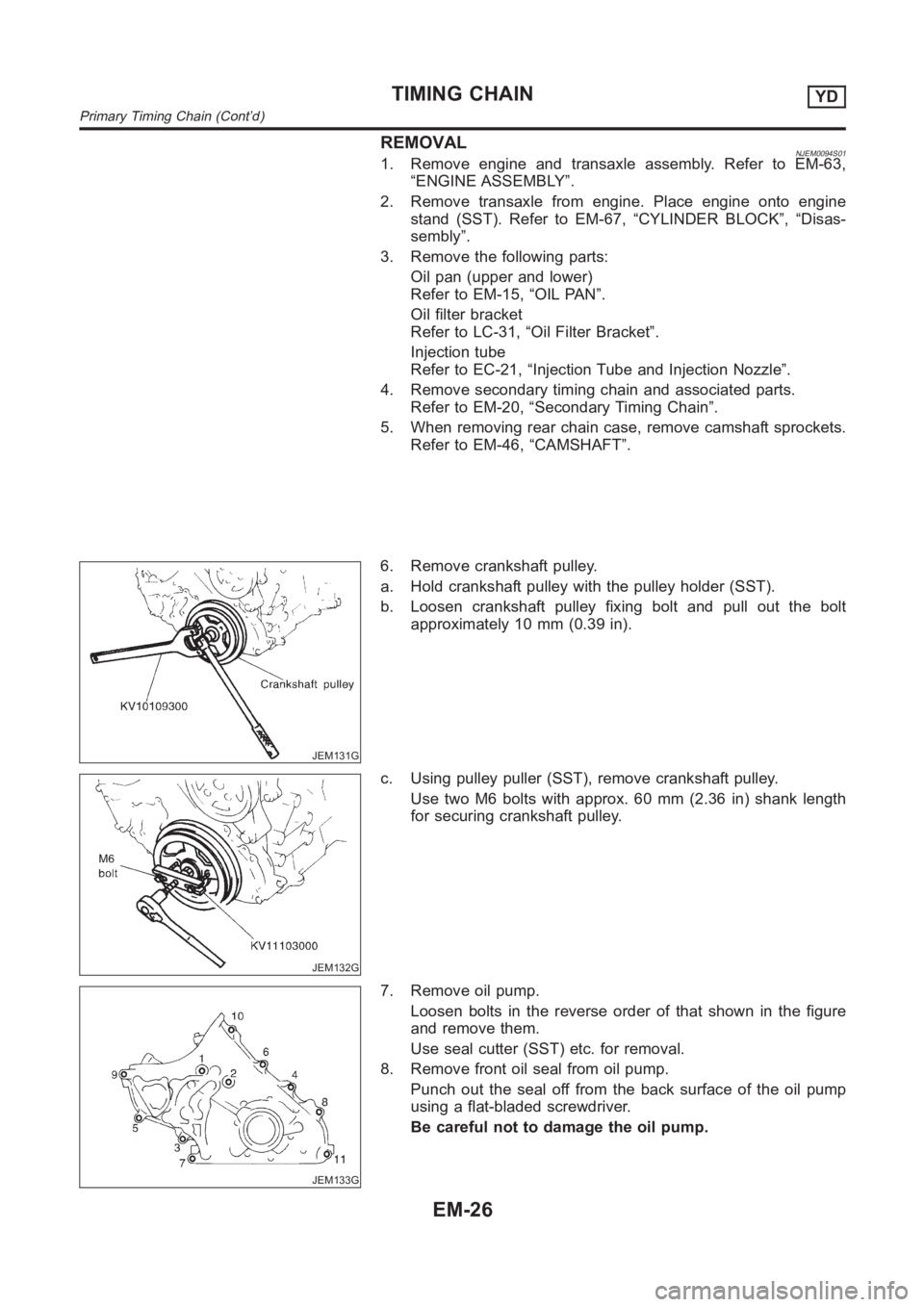
6. Remove crankshaft pulley.
a. Hold crankshaft pulley with the pulley holder (SST).
b. Loosen crankshaft pulley fixing bolt and pull out the bolt
approximately 10 mm (0.39 in).
JEM132G
c. Using pulley puller (SST), remove crankshaft pulley.
Use two M6 bolts with approx. 60 mm (2.36 in) shank length
for securing crankshaft pulley.
JEM133G
7. Remove oil pump.
Loosen bolts in the reverse order of that shown in the figure
and remove them.
Use seal cutter (SST) etc. for removal.
8. Remove front oil seal from oil pump.
Punch out the seal off from the back surface of the oil pump
using a flat-bladed screwdriver.
Be careful not to damage the oil pump.
TIMING CHAINYD
Primary Timing Chain (Cont’d)
EM-26
Page 214 of 3189
JEM137G
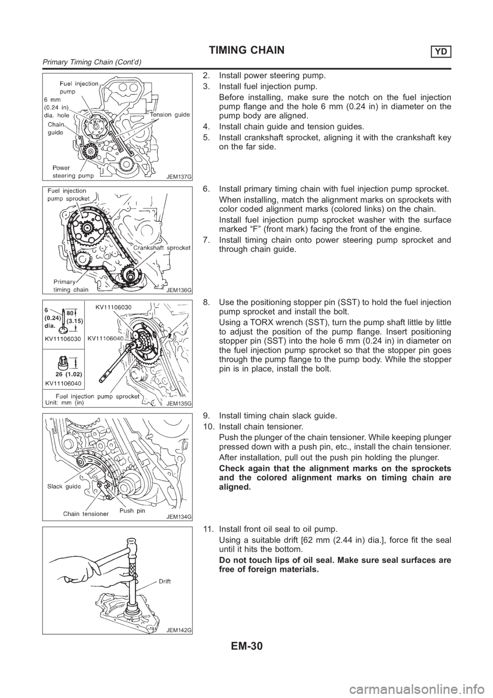
2. Install power steering pump.
3. Install fuel injection pump.
Before installing, make sure the notch on the fuel injection
pump flange and the hole 6 mm (0.24 in) in diameter on the
pump body are aligned.
4. Install chain guide and tension guides.
5. Install crankshaft sprocket, aligning it with the crankshaft key
on the far side.
JEM136G
6. Install primary timing chain with fuel injection pump sprocket.
When installing, match the alignment marks on sprockets with
color coded alignment marks (colored links) on the chain.
Install fuel injection pump sprocket washer with the surface
marked “F” (front mark) facing the front of the engine.
7. Install timing chain onto power steering pump sprocket and
through chain guide.
JEM135G
8. Use the positioning stopper pin (SST) to hold the fuel injection
pump sprocket and install the bolt.
Using a TORX wrench (SST), turn the pump shaft little by little
to adjust the position of the pump flange. Insert positioning
stopper pin (SST) into the hole 6 mm (0.24 in) in diameter on
the fuel injection pump sprocket so that the stopper pin goes
through the pump flange to the pump body. While the stopper
pin is in place, install the bolt.
JEM134G
9. Install timing chain slack guide.
10. Install chain tensioner.
Push the plunger of the chain tensioner. While keeping plunger
pressed down with a push pin, etc., install the chain tensioner.
After installation, pull out the push pin holding the plunger.
Check again that the alignment marks on the sprockets
and the colored alignment marks on timing chain are
aligned.
JEM142G
11. Install front oil seal to oil pump.
Using a suitable drift [62 mm (2.44 in) dia.], force fit the seal
until it hits the bottom.
Do not touch lips of oil seal. Make sure seal surfaces are
free of foreign materials.
TIMING CHAINYD
Primary Timing Chain (Cont’d)
EM-30
Page 215 of 3189
JEM143G
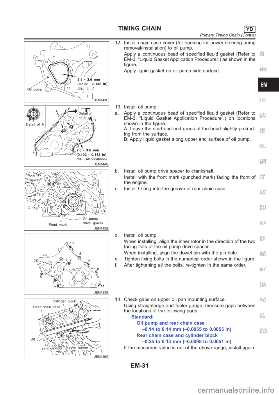
12. Install chain case cover (for opening for power steering pump
removal/installation) to oil pump.
Apply a continuous bead of specified liquid gasket (Refer to
EM-3, “Liquid Gasket Application Procedure”.) as shown in the
figure.
Apply liquid gasket on oil pump-side surface.
JEM144G
13. Install oil pump.
a. Apply a continuous bead of specified liquid gasket (Refer to
EM-3, “Liquid Gasket Application Procedure”.) on locations
shown in the figure.
A: Leave the start and end areas of the bead slightly protrud-
ing from the surface.
B: Apply liquid gasket along upper end surface of oil pump.
JEM145G
b. Install oil pump drive spacer to crankshaft.
Install with the front mark (punched mark) facing the front of
the engine.
c. Install O-ring into the groove of rear chain case.
JEM133G
d. Install oil pump.
When installing, align the inner rotor in the direction of the two
facing flats of the oil pump drive spacer.
When installing, align the dowel pin with the pin hole.
e. Tighten fixing bolts in the numerical order shown in the figure.
f. After tightening all the bolts, re-tighten in the same order.
JEM146G
14. Check gaps on upper oil pan mounting surface.
Using straightedge and feeler gauge, measure gaps between
the locations of the following parts:
Standard:
Oil pump and rear chain case
–0.14 to 0.14 mm (–0.0055 to 0.0055 in)
Rear chain case and cylinder block
–0.25 to 0.13 mm (–0.0098 to 0.0051 in)
If the measured value is out of the above range, install again.
GI
MA
LC
EC
FE
CL
MT
AT
AX
SU
BR
ST
RS
BT
HA
SC
EL
IDX
TIMING CHAINYD
Primary Timing Chain (Cont’d)
EM-31
Page 220 of 3189
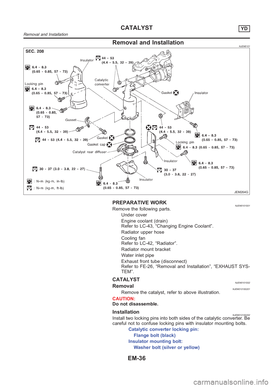
Removal and InstallationNJEM0101
JEM264G
PREPARATIVE WORKNJEM0101S01Remove the following parts.
Under cover
Engine coolant (drain)
Refer to LC-43, “Changing Engine Coolant”.
Radiator upper hose
Cooling fan
Refer to LC-42, “Radiator”.
Radiator mount bracket
Water inlet pipe
Exhaust front tube (disconnect)
Refer to FE-26, “Removal and Installation”, “EXHAUST SYS-
TEM”.
CATALYSTNJEM0101S02RemovalNJEM0101S0201Remove the catalyst, refer to above illustration.
CAUTION:
Do not disassemble.
InstallationNJEM0101S0202Install two locking pins into both sides of the catalytic converter. Be
careful not to confuse locking pins with insulator mounting bolts.
Catalytic converter locking pin:
Flange bolt (black)
Insulator mounting bolt:
Washer bolt (silver or yellow)
CATALYSTYD
Removal and Installation
EM-36
Page 240 of 3189
Installation=NJEM0067Before installation, remove old liquid gasket from mating
surface of all liquid gasket applied parts.
SEM505G
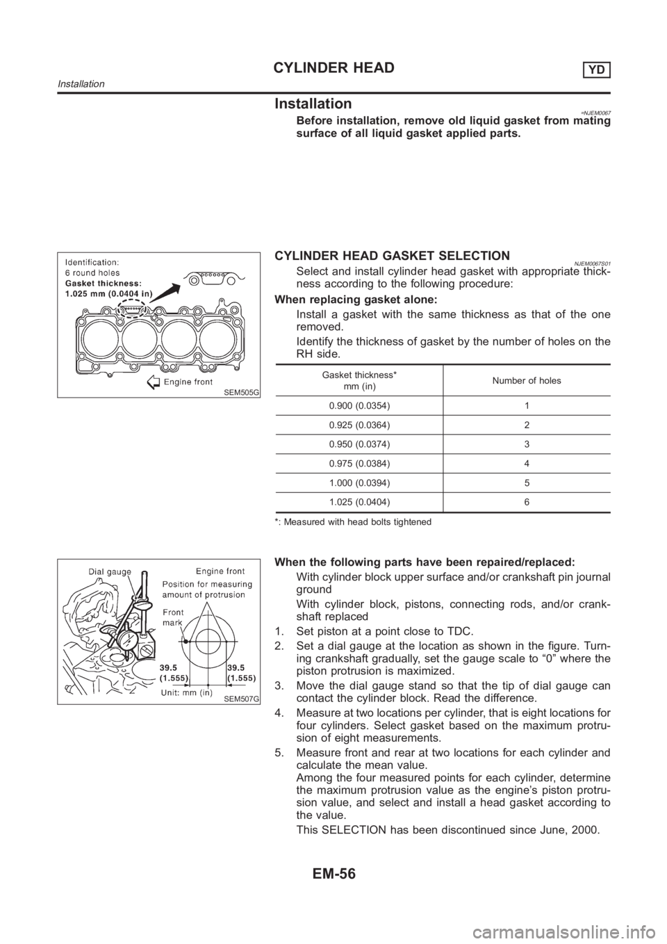
CYLINDER HEAD GASKET SELECTIONNJEM0067S01Select and install cylinder head gasket with appropriate thick-
ness according to the following procedure:
When replacing gasket alone:
Install a gasket with the same thickness as that of the one
removed.
Identify the thickness of gasket by the number of holes on the
RH side.
Gasket thickness*
mm (in)Number of holes
0.900 (0.0354) 1
0.925 (0.0364) 2
0.950 (0.0374) 3
0.975 (0.0384) 4
1.000 (0.0394) 5
1.025 (0.0404) 6
*: Measured with head bolts tightened
SEM507G
When the following parts have been repaired/replaced:
With cylinder block upper surface and/or crankshaft pin journal
ground
With cylinder block, pistons, connecting rods, and/or crank-
shaft replaced
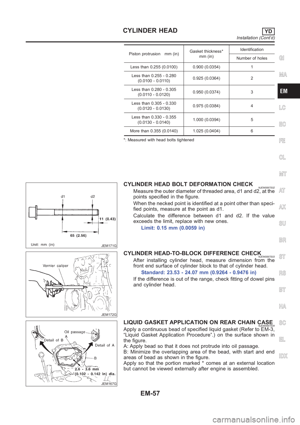
1. Set piston at a point close to TDC.
2. Set a dial gauge at the location as shown in the figure. Turn-
ing crankshaft gradually, set the gauge scale to “0” where the
piston protrusion is maximized.
3. Move the dial gauge stand so that the tip of dial gauge can
contact the cylinder block. Read the difference.
4. Measure at two locations per cylinder, that is eight locations for
four cylinders. Select gasket based on the maximum protru-
sion of eight measurements.
5. Measure front and rear at two locations for each cylinder and
calculate the mean value.
Among the four measured points for each cylinder, determine
the maximum protrusion value as the engine’s piston protru-
sion value, and select and install a head gasket according to
the value.
This SELECTION has been discontinued since June, 2000.
CYLINDER HEADYD
Installation
EM-56
Page 241 of 3189
Piston protrusion mm (in)Gasket thickness*
mm (in)Identification
Number of holes
Less than 0.255 (0.0100) 0.900 (0.0354) 1
Less than 0.255 - 0.280
(0.0100 - 0.0110)0.925 (0.0364) 2
Less than 0.280 - 0.305
(0.0110 - 0.0120)0.950 (0.0374) 3
Less than 0.305 - 0.330
(0.0120 - 0.0130)0.975 (0.0384) 4
Less than 0.330 - 0.355
(0.0130 - 0.0140)1.000 (0.0394) 5
More than 0.355 (0.0140) 1.025 (0.0404) 6
*: Measured with head bolts tightened
JEM171G
CYLINDER HEAD BOLT DEFORMATION CHECKNJEM0067S02Measure the outer diameter of threaded area, d1 and d2, at the
points specified in the figure.
When the necked point is identified at a point other than speci-
fied points, measure at the point as d1.
Calculate the difference between d1 and d2. If the value
exceeds the limit, replace with new ones.
Limit: 0.15 mm (0.0059 in)
JEM172G
CYLINDER HEAD-TO-BLOCK DIFFERENCE CHECKNJEM0067S03After installing cylinder head, measure dimension from the
front end surface of cylinder block to that of cylinder head.
Standard: 23.53 - 24.07 mm (0.9264 - 0.9476 in)
If the difference is out of the range, check fitting of dowel pins
and cylinder head.
JEM167G
LIQUID GASKET APPLICATION ON REAR CHAIN CASENJEM0067S04Apply a continuous bead of specified liquid gasket (Refer to EM-3,
“Liquid Gasket Application Procedure”.) on the surface shown in
the figure.
A: Apply bead so that it does not protrude into oil passage.
B: Minimize the overlapping area of the bead, with start and end
areas of bead as shown in the figure.
Apply so that the portion marked * comes at an external location
but cannot be viewed externally after engine is assembled.
GI
MA
LC
EC
FE
CL
MT
AT
AX
SU
BR
ST
RS
BT
HA
SC
EL
IDX
CYLINDER HEADYD
Installation (Cont’d)
EM-57
Page 243 of 3189
JEM175G
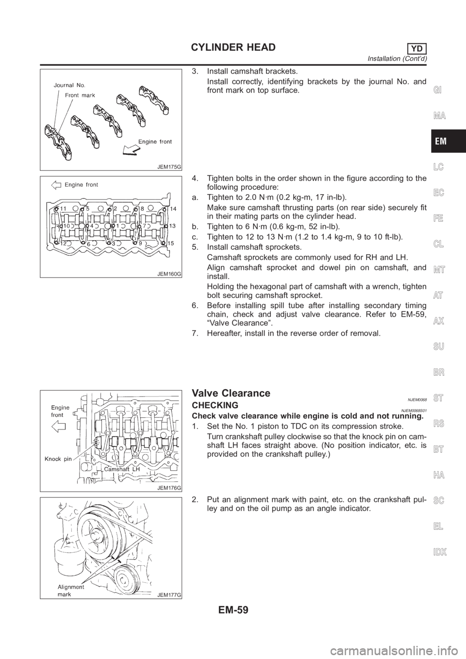
3. Install camshaft brackets.
Install correctly, identifying brackets by the journal No. and
front mark on top surface.
JEM160G
4. Tighten bolts in the order shown in the figure according to the
following procedure:
a. Tighten to 2.0 N·m (0.2 kg-m, 17 in-lb).
Make sure camshaft thrusting parts (on rear side) securely fit
in their mating parts on the cylinder head.
b. Tighten to 6 N·m (0.6 kg-m, 52 in-lb).
c. Tightento12to13N·m(1.2to1.4kg-m,9to10ft-lb).
5. Install camshaft sprockets.
Camshaft sprockets are commonly used for RH and LH.
Align camshaft sprocket and dowel pin on camshaft, and
install.
Holding the hexagonal part of camshaft with a wrench, tighten
bolt securing camshaft sprocket.
6. Before installing spill tube after installing secondary timing
chain, check and adjust valve clearance. Refer to EM-59,
“Valve Clearance”.
7. Hereafter, install in the reverse order of removal.
JEM176G
Valve ClearanceNJEM0068CHECKINGNJEM0068S01Check valve clearance while engine is cold and not running.
1. Set the No. 1 piston to TDC on its compression stroke.
Turn crankshaft pulley clockwise so that the knock pin on cam-
shaft LH faces straight above. (No position indicator, etc. is
provided on the crankshaft pulley.)
JEM177G
2. Put an alignment mark with paint, etc. on the crankshaft pul-
ley and on the oil pump as an angle indicator.
GI
MA
LC
EC
FE
CL
MT
AT
AX
SU
BR
ST
RS
BT
HA
SC
EL
IDX
CYLINDER HEADYD
Installation (Cont’d)
EM-59
Page 247 of 3189
Removal and InstallationNJEM0069
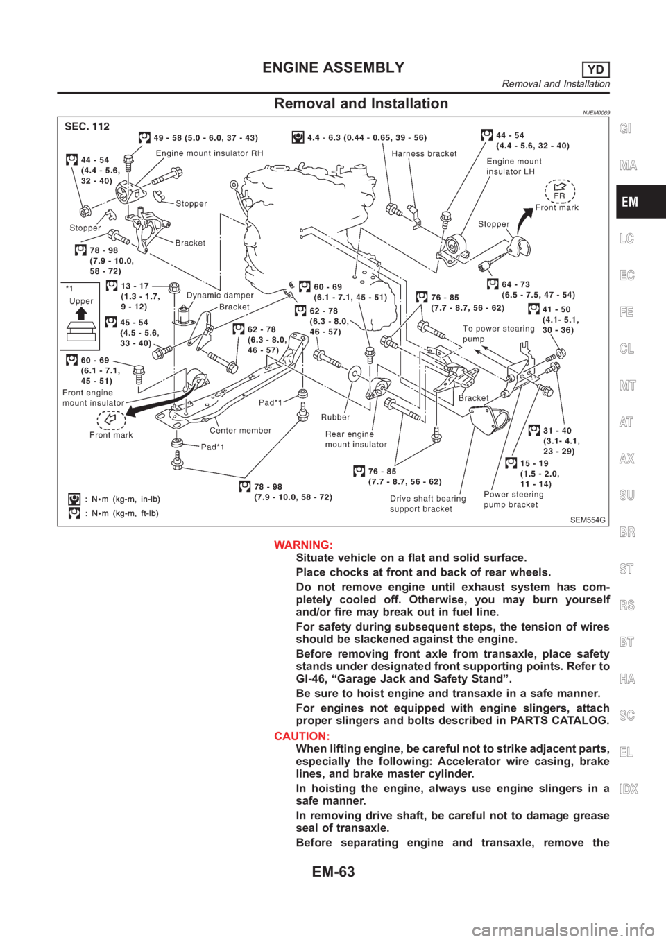
SEM554G
WARNING:
Situate vehicle on a flat and solid surface.
Place chocks at front and back of rear wheels.
Do not remove engine until exhaust system has com-
pletely cooled off. Otherwise, you may burn yourself
and/or fire may break out in fuel line.
For safety during subsequent steps, the tension of wires
should be slackened against the engine.
Before removing front axle from transaxle, place safety
stands under designated front supporting points. Refer to
GI-46, “Garage Jack and Safety Stand”.
Be sure to hoist engine and transaxle in a safe manner.
For engines not equipped with engine slingers, attach
proper slingers and bolts described in PARTS CATALOG.
CAUTION:
When lifting engine, be careful not to strike adjacent parts,
especially the following: Accelerator wire casing, brake
lines, and brake master cylinder.
In hoisting the engine, always use engine slingers in a
safe manner.
In removing drive shaft, be careful not to damage grease
seal of transaxle.
Before separating engine and transaxle, remove the
GI
MA
LC
EC
FE
CL
MT
AT
AX
SU
BR
ST
RS
BT
HA
SC
EL
IDX
ENGINE ASSEMBLYYD
Removal and Installation
EM-63