Page 288 of 3189
DISASSEMBLY AND ASSEMBLYNJLC0006
YLC022
1. Oil pump cover
2. Inner rotor
3. Outer rotor4. Front cover
5. Oil strainer
6. Regulator valve7. Spring
8. Washer
9. Plug
When installing oil pump, apply engine oil to rotors.
JLC307B
Install the inner rotor and outer rotor with the punched
marks on the oil pump cover side.
ENGINE LUBRICATION SYSTEMQG
Oil Pump (Cont’d)
LC-6
Page 289 of 3189

SEM855F
SEM856F
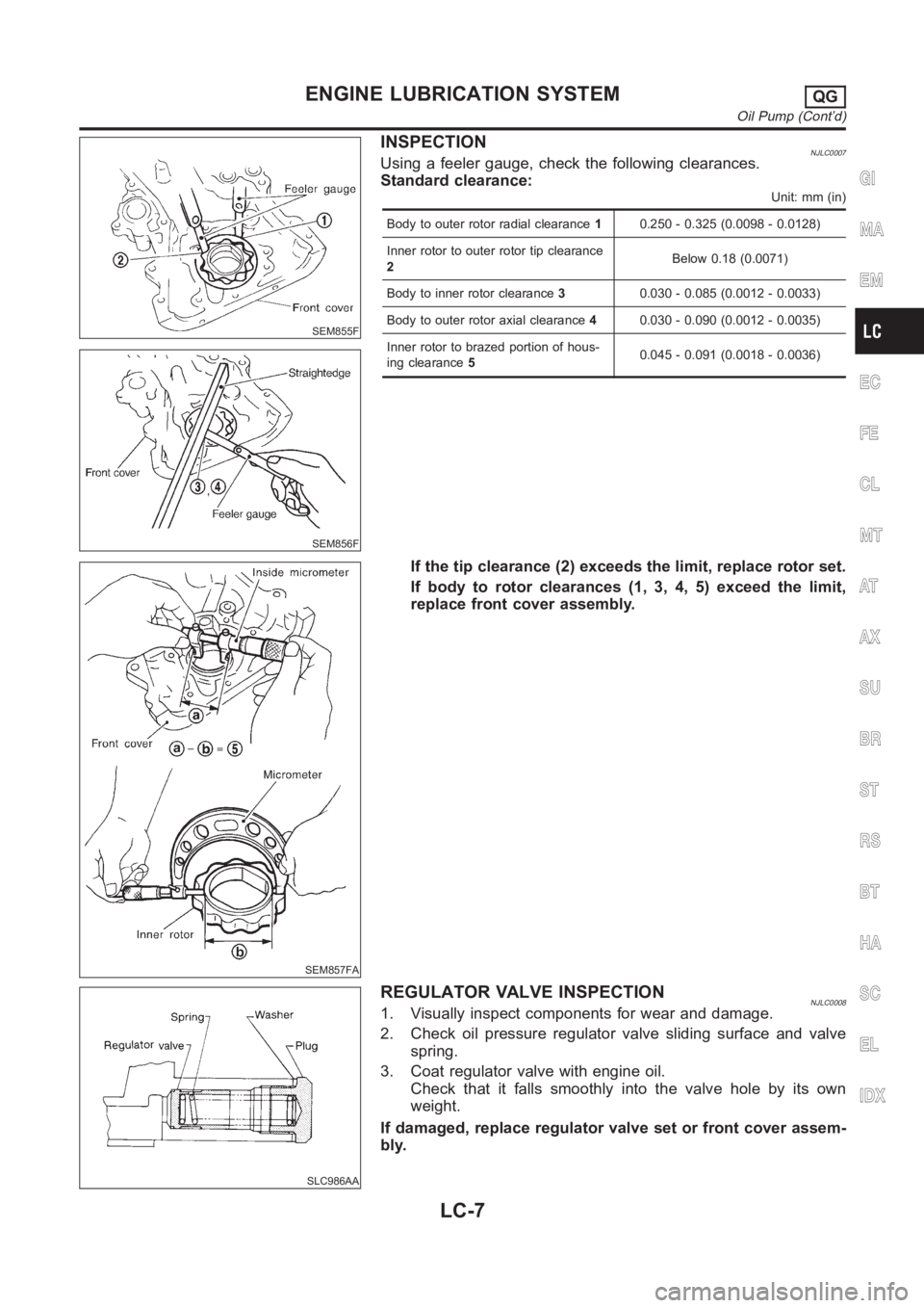
INSPECTIONNJLC0007Using a feeler gauge, check the following clearances.
Standard clearance:
Unit: mm (in)
Body to outer rotor radial clearance10.250 - 0.325 (0.0098 - 0.0128)
Inner rotor to outer rotor tip clearance
2Below 0.18 (0.0071)
Body to inner rotor clearance30.030 - 0.085 (0.0012 - 0.0033)
Body to outer rotor axial clearance40.030 - 0.090 (0.0012 - 0.0035)
Inner rotor to brazed portion of hous-
ing clearance50.045 - 0.091 (0.0018 - 0.0036)
SEM857FA
If the tip clearance (2) exceeds the limit, replace rotor set.
If body to rotor clearances (1, 3, 4, 5) exceed the limit,
replace front cover assembly.
SLC986AA
REGULATOR VALVE INSPECTIONNJLC00081. Visually inspect components for wear and damage.
2. Check oil pressure regulator valve sliding surface and valve
spring.
3. Coat regulator valve with engine oil.
Check that it falls smoothly into the valve hole by its own
weight.
If damaged, replace regulator valve set or front cover assem-
bly.
GI
MA
EM
EC
FE
CL
MT
AT
AX
SU
BR
ST
RS
BT
HA
SC
EL
IDX
ENGINE LUBRICATION SYSTEMQG
Oil Pump (Cont’d)
LC-7
Page 290 of 3189

SLC101B
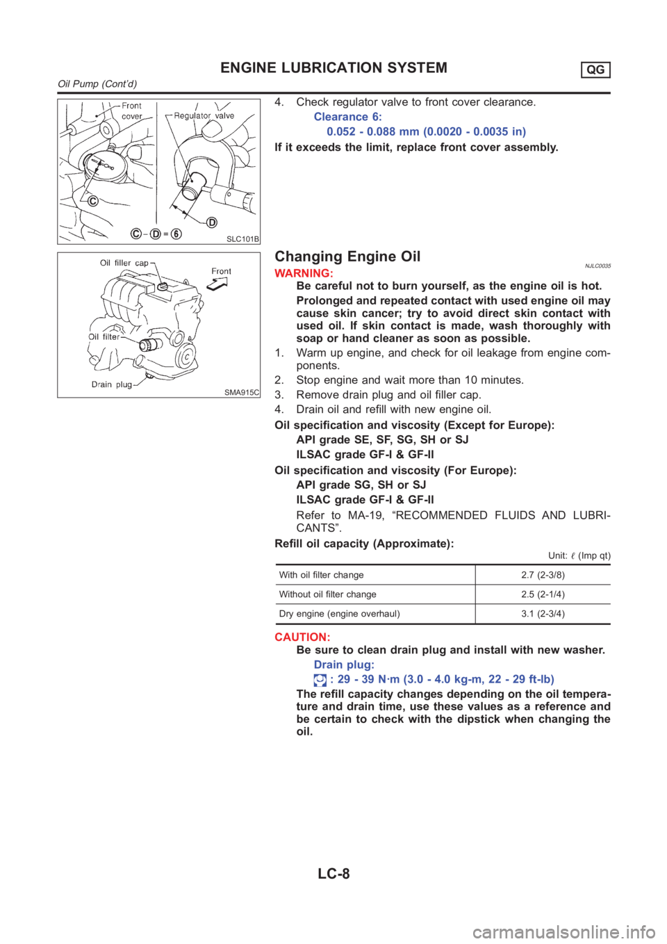
4. Check regulator valve to front cover clearance.
Clearance 6:
0.052 - 0.088 mm (0.0020 - 0.0035 in)
If it exceeds the limit, replace front cover assembly.
SMA915C
Changing Engine OilNJLC0035WARNING:
Be careful not to burn yourself, as the engine oil is hot.
Prolonged and repeated contact with used engine oil may
cause skin cancer; try to avoid direct skin contact with
used oil. If skin contact is made, wash thoroughly with
soap or hand cleaner as soon as possible.
1. Warm up engine, and check for oil leakage from engine com-
ponents.
2. Stop engine and wait more than 10 minutes.
3. Remove drain plug and oil filler cap.
4. Drain oil and refill with new engine oil.
Oil specification and viscosity (Except for Europe):
API grade SE, SF, SG, SH or SJ
ILSAC grade GF-I & GF-II
Oil specification and viscosity (For Europe):
API grade SG, SH or SJ
ILSAC grade GF-I & GF-II
Refer to MA-19, “RECOMMENDED FLUIDS AND LUBRI-
CANTS”.
Refill oil capacity (Approximate):
Unit:�(Imp qt)
With oil filter change 2.7 (2-3/8)
Without oil filter change 2.5 (2-1/4)
Dry engine (engine overhaul) 3.1 (2-3/4)
CAUTION:
Be sure to clean drain plug and install with new washer.
Drain plug:
: 29 - 39 N·m (3.0 - 4.0 kg-m, 22 - 29 ft-lb)
The refill capacity changes depending on the oil tempera-
ture and drain time, use these values as a reference and
be certain to check with the dipstick when changing the
oil.
ENGINE LUBRICATION SYSTEMQG
Oil Pump (Cont’d)
LC-8
Page 296 of 3189
Water Pump
REMOVAL AND INSTALLATIONNJLC0018
SEM858F
SEM859F
CAUTION:
When removing water pump assembly, be careful not to
get coolant on drive belt.
Water pump cannot be disassembled and should be
replaced as a unit.
After installing water pump, and check for leaks using
radiator cap tester.
1. Drain engine coolant.
Refer to LC-17, “Changing Engine Coolant”.
2. Remove drive belts and idler pulley.
3. Loosen water pump pulley bolts.
4. Remove water pump pulley.
5. Remove front right wheel.
6. Remove front right undercover and front right fender protector.
7. Remove water pump bolts.
8. Remove water pump.
9. Reinstall parts in reverse order of removal.
SEM860F
INSPECTIONNJLC0019Check body assembly and vane for rust or corrosion.
Check for rough operation due to excessive end play.
ENGINE COOLING SYSTEMQG
Water Pump
LC-14
Page 309 of 3189

SLC283B
Oil Pressure Check
JLC284B
SLC926-A
NJLC0042WARNING:
Be careful not to burn yourself, as the engine and oil may
be hot.
Oil pressure check should be done in “Neutral position”.
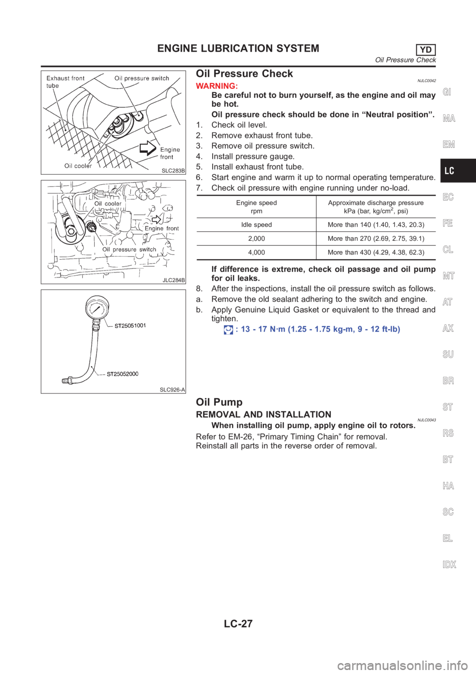
1. Check oil level.
2. Remove exhaust front tube.
3. Remove oil pressure switch.
4. Install pressure gauge.
5. Install exhaust front tube.
6. Start engine and warm it up to normal operating temperature.
7. Check oil pressure with engine running under no-load.
Engine speed
rpmApproximate discharge pressure
kPa (bar, kg/cm2, psi)
Idle speed More than 140 (1.40, 1.43, 20.3)
2,000 More than 270 (2.69, 2.75, 39.1)
4,000 More than 430 (4.29, 4.38, 62.3)
If difference is extreme, check oil passage and oil pump
for oil leaks.
8. After the inspections, install the oil pressure switch as follows.
a. Remove the old sealant adhering to the switch and engine.
b. Apply Genuine Liquid Gasket or equivalent to the thread and
tighten.
: 13 - 17 N·m (1.25 - 1.75 kg-m, 9 - 12 ft-lb)
Oil Pump
REMOVAL AND INSTALLATIONNJLC0043When installing oil pump, apply engine oil to rotors.
Refer to EM-26, “Primary Timing Chain” for removal.
Reinstall all parts in the reverse order of removal.
GI
MA
EM
EC
FE
CL
MT
AT
AX
SU
BR
ST
RS
BT
HA
SC
EL
IDX
ENGINE LUBRICATION SYSTEMYD
Oil Pressure Check
LC-27
Page 313 of 3189
Oil Filter BracketNJLC0075
JLC301B
REMOVAL AND INSTALLATIONNJLC0075S011. Remove the undercover.
2. Steer the front wheel to the right.
3. Remove the right splash cover.
4. Remove the oil filter bracket bolt.
5. Reinstall all removed parts in the reverse order of removal.
Insert the top mounting bolt to the oil filter bracket beforehand,
and set the oil filter bracket to the installation location.
JLC289B
Changing Oil FilterNJLC0076
GI
MA
EM
EC
FE
CL
MT
AT
AX
SU
BR
ST
RS
BT
HA
SC
EL
IDX
ENGINE LUBRICATION SYSTEMYD
Oil Filter Bracket
LC-31
Page 315 of 3189
Oil CoolerNJLC0077
YLC015
REMOVAL AND INSTALLATIONNJLC0077S011. Draining the coolant
Refer to LC-43, “Changing Engine Coolant”.
2. Remove the exhaust front tube.
YLC027
3. Reinstall all removed parts in the reverse order of removal.
Confirm that no foreign objects are adhering to the installation
planes of the oil cooler or block.
Tighten the connecting bolt after aligning the stopper on the
cylinder block side with protrusion of the oil cooler.
GI
MA
EM
EC
FE
CL
MT
AT
AX
SU
BR
ST
RS
BT
HA
SC
EL
IDX
ENGINE LUBRICATION SYSTEMYD
Oil Cooler
LC-33
Page 321 of 3189
JLC294B
REMOVALNJLC00561. Remove the undercover, splash cover (right), and accessory
belt.
2. Drain engine coolant. Refer to LC-43, “Changing Engine Cool-
ant”.
3. Support the bottom of the oil pan with a floor jack etc., and
remove the right engine mount bracket (front side of the
engine).
4. Remove the water pump pulley.
Loosen the pulley bolts after fixing the pulley using a screw-
driver etc.
5. Remove engine mount brackets.
6. Remove the water pump.
INSPECTIONNJLC0057Check for rust and contamination adhering to the water pump
and vane.
Turn the pump shaft by hand, and check that the pump turns
smoothly without looseness.
INSTALLATIONNJLC0058Install the parts in the reverse order of removal.
Install the water pump pulley with the front mark (painted white,
used to prevent errors during assembly) facing the front of the
engine. Refer to the figure above.
GI
MA
EM
EC
FE
CL
MT
AT
AX
SU
BR
ST
RS
BT
HA
SC
EL
IDX
ENGINE COOLING SYSTEMYD
Water Pump (Cont’d)
LC-39