2003 NISSAN ALMERA N16 Front
[x] Cancel search: FrontPage 345 of 3189
![NISSAN ALMERA N16 2003 Electronic Repair Manual PRECAUTIONS
EC-15
[QG (WITH EURO-OBD)]
C
D
E
F
G
H
I
J
K
L
MA
EC
PRECAUTIONSPFP:00001
Precautions for Supplemental Restraint System (SRS) “AIR BAG” and “SEAT
BELT PRE-TENSIONER”
EBS00K2V
The NISSAN ALMERA N16 2003 Electronic Repair Manual PRECAUTIONS
EC-15
[QG (WITH EURO-OBD)]
C
D
E
F
G
H
I
J
K
L
MA
EC
PRECAUTIONSPFP:00001
Precautions for Supplemental Restraint System (SRS) “AIR BAG” and “SEAT
BELT PRE-TENSIONER”
EBS00K2V
The](/manual-img/5/57350/w960_57350-344.png)
PRECAUTIONS
EC-15
[QG (WITH EURO-OBD)]
C
D
E
F
G
H
I
J
K
L
MA
EC
PRECAUTIONSPFP:00001
Precautions for Supplemental Restraint System (SRS) “AIR BAG” and “SEAT
BELT PRE-TENSIONER”
EBS00K2V
The Supplemental Restraint System such as “AIR BAG” and “SEAT BELT PRE-TENSIONER”, used along
with a front seat belt, helps to reduce the risk or severity of injury to the driver and front passenger for certain
types of collision. Information necessary to service the system safely is included in the SRS and SB section of
this Service Manual.
WARNING:
●To avoid rendering the SRS inoperative, which could increase the risk of personal injury or death
in the event of a collision which would result in air bag inflation, all maintenance must be per-
formed by an authorized NISSAN/INFINITI dealer.
●Improper maintenance, including incorrect removal and installation of the SRS, can lead to per-
sonal injury caused by unintentional activation of the system. For removal of Spiral Cable and Air
Bag Module, see the SRS section.
●Do not use electrical test equipment on any circuit related to the SRS unless instructed to in this
Service Manual. SRS wiring harnesses can be identified by yellow and/or orange harness connec-
tors.
On Board Diagnostic (OBD) System of Engine and A/TEBS00K2W
The ECM has an on board diagnostic system. It will light up the malfunction indicator (MI) to warn the driver of
a malfunction causing emission deterioration.
CAUTION:
●Be sure to turn the ignition switch OFF and disconnect the battery ground cable before any repair
or inspection work. The open/short circuit of related switches, sensors, solenoid valves, etc. will
cause the MI to light up.
●Be sure to connect and lock the connectors securely after work. A loose (unlocked) connector will
cause the MI to light up due to the open circuit. (Be sure the connector is free from water, grease,
dirt, bent terminals, etc.)
●Certain systems and components, especially those related to OBD, may use a new style slide-
locking type harness connector. For description and how to disconnect, refer to EL-7.
●Be sure to route and secure the harnesses properly after work. The interference of the harness
with a bracket, etc. may cause the MI to light up due to the short circuit.
●Be sure to connect rubber tubes properly after work. A misconnected or disconnected rubber tube
may cause the MI to light up due to the malfunction of the fuel injection system, etc.
●Be sure to erase the unnecessary malfunction information (repairs completed) from the ECM and
TCM (Transmission control module) before returning the vehicle to the customer.
PrecautionEBS00K2X
●Always use a 12 volt battery as power source.
●Do not attempt to disconnect battery cables while engine is
running.
●Before connecting or disconnecting the ECM harness con-
nector, turn ignition switch OFF and disconnect battery
ground cable. Failure to do so may damage the ECM
because battery voltage is applied to ECM even if ignition
switch is turned off.
●Before removing parts, turn ignition switch OFF and then
disconnect battery ground cable.
SEF289H
Page 739 of 3189
![NISSAN ALMERA N16 2003 Electronic Repair Manual PRECAUTIONS
EC-409
[QG (WITHOUT EURO-OBD)]
C
D
E
F
G
H
I
J
K
L
MA
EC
PRECAUTIONSPFP:00001
Precautions for Supplemental Restraint System (SRS) “AIR BAG” and “SEAT
BELT PRE-TENSIONER”
EBS00KE2
NISSAN ALMERA N16 2003 Electronic Repair Manual PRECAUTIONS
EC-409
[QG (WITHOUT EURO-OBD)]
C
D
E
F
G
H
I
J
K
L
MA
EC
PRECAUTIONSPFP:00001
Precautions for Supplemental Restraint System (SRS) “AIR BAG” and “SEAT
BELT PRE-TENSIONER”
EBS00KE2](/manual-img/5/57350/w960_57350-738.png)
PRECAUTIONS
EC-409
[QG (WITHOUT EURO-OBD)]
C
D
E
F
G
H
I
J
K
L
MA
EC
PRECAUTIONSPFP:00001
Precautions for Supplemental Restraint System (SRS) “AIR BAG” and “SEAT
BELT PRE-TENSIONER”
EBS00KE2
The Supplemental Restraint System such as “AIR BAG” and “SEAT BELT PRE-TENSIONER”, used along
with a front seat belt, helps to reduce the risk or severity of injury to the driver and front passenger for certain
types of collision. Information necessary to service the system safely is included in the SRS and SB section of
this Service Manual.
WARNING:
●To avoid rendering the SRS inoperative, which could increase the risk of personal injury or death
in the event of a collision which would result in air bag inflation, all maintenance must be per-
formed by an authorized NISSAN/INFINITI dealer.
●Improper maintenance, including incorrect removal and installation of the SRS, can lead to per-
sonal injury caused by unintentional activation of the system. For removal of Spiral Cable and Air
Bag Module, see the SRS section.
●Do not use electrical test equipment on any circuit related to the SRS unless instructed to in this
Service Manual. SRS wiring harnesses can be identified by yellow and/or orange harness connec-
tors.
On Board Diagnostic (OBD) System of EngineEBS00KE3
The ECM has an on board diagnostic system. It will light up the malfunction indicator (MI) to warn the driver of
a malfunction causing emission deterioration.
CAUTION:
●Be sure to turn the ignition switch OFF and disconnect the battery ground cable before any repair
or inspection work. The open/short circuit of related switches, sensors, solenoid valves, etc. will
cause the MI to light up.
●Be sure to connect and lock the connectors securely after work. A loose (unlocked) connector will
cause the MI to light up due to the open circuit. (Be sure the connector is free from water, grease,
dirt, bent terminals, etc.)
●Certain systems and components, especially those related to OBD, may use a new style slide-
locking type harness connector. For description and how to disconnect, refer to EL-7.
●Be sure to route and secure the harnesses properly after work. The interference of the harness
with a bracket, etc. may cause the MI to light up due to the short circuit.
●Be sure to connect rubber tubes properly after work. A misconnected or disconnected rubber tube
may cause the MI to light up due to the malfunction of the fuel injection system, etc.
●Be sure to erase the unnecessary malfunction information (repairs completed) from the ECM
before returning the vehicle to the customer.
PrecautionEBS00KE4
●Always use a 12 volt battery as power source.
●Do not attempt to disconnect battery cables while engine is
running.
●Before connecting or disconnecting the ECM harness con-
nector, turn ignition switch OFF and disconnect battery
ground cable. Failure to do so may damage the ECM
because battery voltage is applied to ECM even if ignition
switch is turned off.
●Before removing parts, turn ignition switch OFF and then
disconnect battery ground cable.
SEF289H
Page 1060 of 3189
Supplemental Restraint System (SRS) “AIR
BAG” and “SEAT BELT PRE-TENSIONER”
NJEC0601The Supplemental Restraint System such as “AIR BAG” and “SEAT BELT PRE-TENSIONER” used along with
a seat belt, helps to reduce the risk or severity of injury to the driver and front passenger for certain types of
collision. The SRS system composition which is available to NISSAN MODEL N16 is as follows (The compo-
sition varies according to the destination and optional equipment.):
For a frontal collision
The Supplemental Restraint System consists of driver air bag module (located in the center of the steer-
ing wheel), front passenger air bag module (located on the instrument panel on passenger side), front seat
belt pre-tensioners, a diagnosis sensor unit, warning lamp, wiring harness and spiral cable.
For a side collision
The Supplemental Restraint System consists of front side air bag module (located in the outer side of front
seat), side air bag (satellite) sensor, diagnosis sensor unit (one of components of air bags for a frontal
collision), wiring harness, warning lamp (one of components of air bags for a frontal collision).
Information necessary to service the system safely is included in theRS sectionof this Service Manual.
WARNING:
To avoid rendering the SRS inoperative, which could increase the risk of personal injury or death
in the event of a collision which would result in air bag inflation, all maintenance should be per-
formed by an authorized NISSAN dealer.
Improper maintenance, including incorrect removal and installation of the SRS, can lead to per-
sonal injury caused by unintentional activation of the system. For removalofSpiralCableandAir
Bag Module, see the RS section.
Do not use electrical test equipment on any circuit related to the SRS unless instructed to in this
Service Manual. SRS wiring harness can be identified by yellow and/or orange harness connector.
PRECAUTIONSYD
Supplemental Restraint System (SRS) “AIR BAG” and “SEAT BELT PRE-TENSIONER”
EC-6
Page 1076 of 3189
JEF341Y
InstallationNJEC0618S01021. Referring to the figure and the marking which were made for
installation, connect the injection tubes to all the cylinders.
2. Connect temporarily the tubes to the cylinder head side only
by screwing 2 to 3 turns. Make sure that all tubes can be con-
nected to the pump side also.
3. Then, tighten the flare nuts of the cylinder head side and pump
side, starting from the opposite side from you.
JEF444Z
4. Attach the injection tube clamp in the direction shown in the
figure.
5. Insert tightening bolts of the clamp (4-tube type) from the rear
to the front of the engine.
JEF343Y
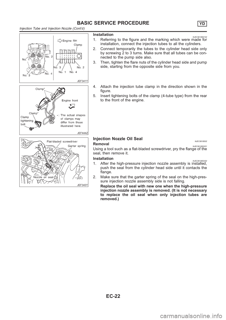
Injection Nozzle Oil SealNJEC0618S02RemovalNJEC0618S0201Using a tool such as a flat-bladed screwdriver, pry the flange of the
seal, then remove it.
Installation
NJEC0618S02021. After the high-pressure injection nozzle assembly is installed,
push the seal from the cylinder head side until it contacts the
flange.
2. Make sure that the garter spring of the seal on the high-pres-
sure injection nozzle assembly side is not falling.
Replace the oil seal with new one when the high-pressure
injection nozzle assembly is removed. (It is not necessary
to replace the oil seal when only injection tubes are
removed.)
BASIC SERVICE PROCEDUREYD
Injection Tube and Injection Nozzle (Cont’d)
EC-22
Page 1079 of 3189
SEF434Z
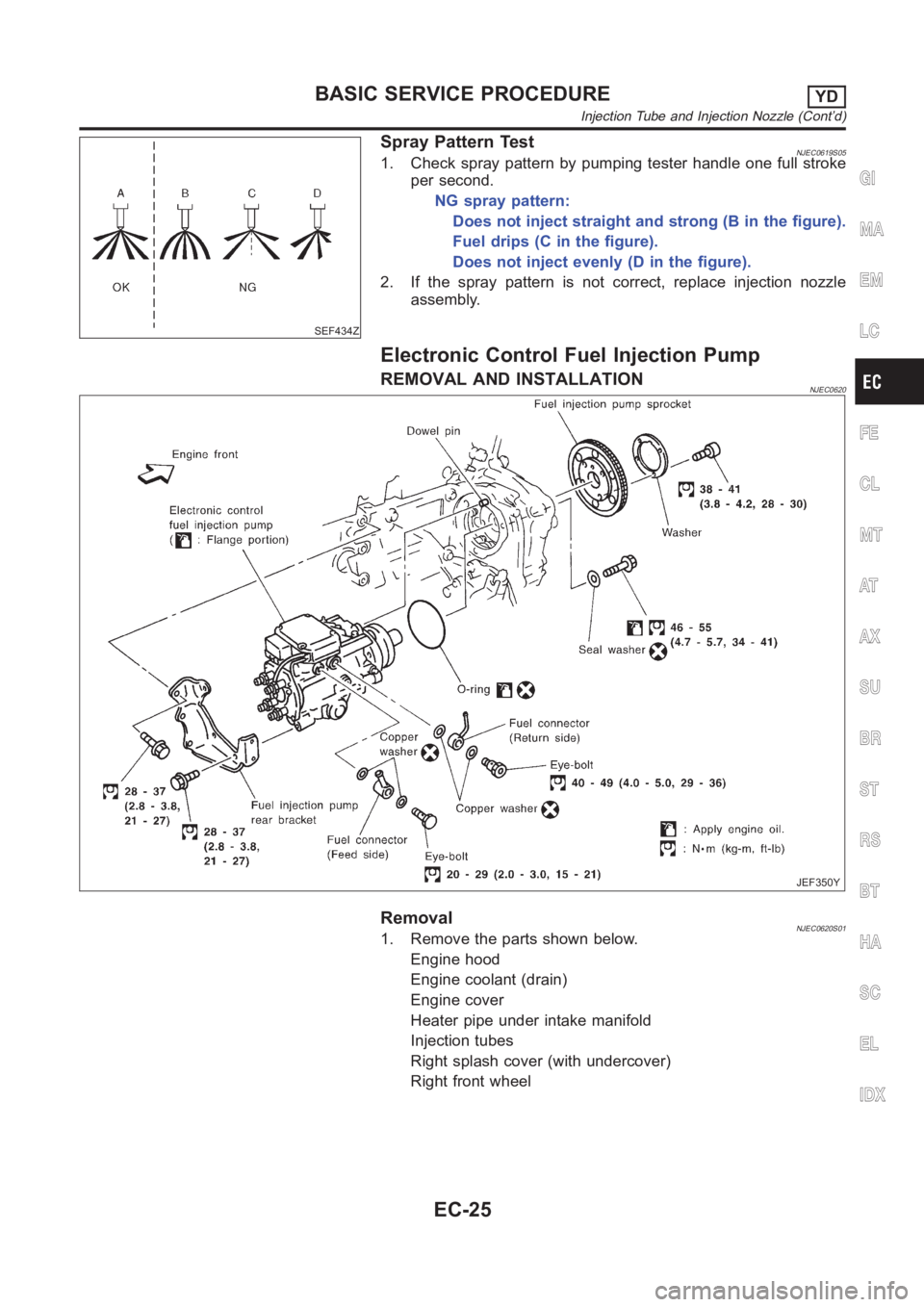
Spray Pattern TestNJEC0619S051. Check spray pattern by pumping tester handle one full stroke
per second.
NG spray pattern:
Does not inject straight and strong (B in the figure).
Fuel drips (C in the figure).
Does not inject evenly (D in the figure).
2. If the spray pattern is not correct, replace injection nozzle
assembly.
Electronic Control Fuel Injection Pump
REMOVAL AND INSTALLATIONNJEC0620
JEF350Y
RemovalNJEC0620S011. Remove the parts shown below.
Engine hood
Engine coolant (drain)
Engine cover
Heater pipe under intake manifold
Injection tubes
Right splash cover (with undercover)
Right front wheel
GI
MA
EM
LC
FE
CL
MT
AT
AX
SU
BR
ST
RS
BT
HA
SC
EL
IDX
BASIC SERVICE PROCEDUREYD
Injection Tube and Injection Nozzle (Cont’d)
EC-25
Page 1080 of 3189
JEF351Y
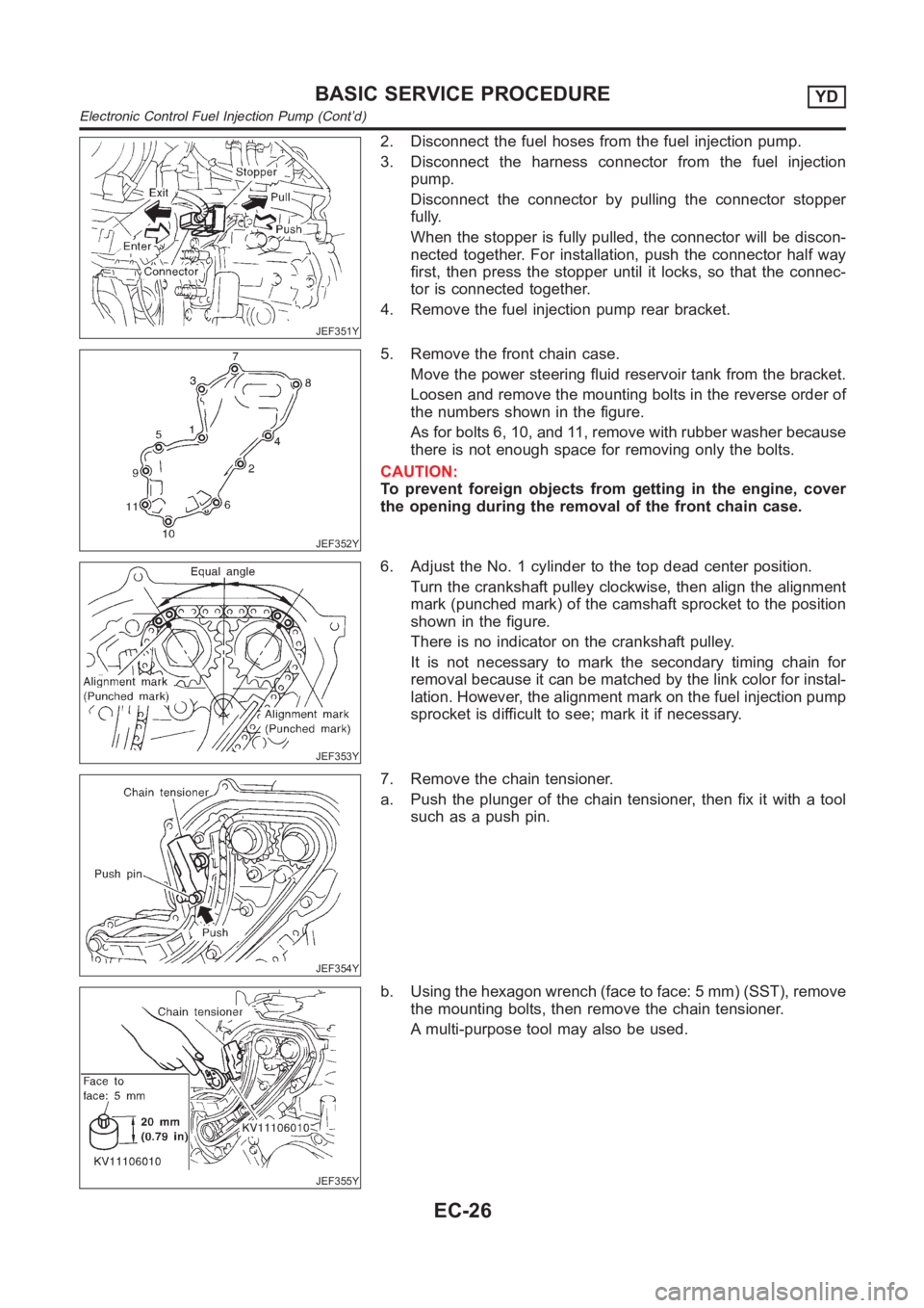
2. Disconnect the fuel hoses from the fuel injection pump.
3. Disconnect the harness connector from the fuel injection
pump.
Disconnect the connector by pulling the connector stopper
fully.
When the stopper is fully pulled, the connector will be discon-
nected together. For installation, push the connector half way
first, then press the stopper until it locks, so that the connec-
tor is connected together.
4. Remove the fuel injection pump rear bracket.
JEF352Y
5. Remove the front chain case.
Move the power steering fluid reservoir tank from the bracket.
Loosen and remove the mounting bolts in the reverse order of
the numbers shown in the figure.
As for bolts 6, 10, and 11, remove with rubber washer because
there is not enough space for removing only the bolts.
CAUTION:
To prevent foreign objects from getting in the engine, cover
the opening during the removal of the front chain case.
JEF353Y
6. Adjust the No. 1 cylinder to the top dead center position.
Turn the crankshaft pulley clockwise, then align the alignment
mark (punched mark) of the camshaft sprocket to the position
shown in the figure.
There is no indicator on the crankshaft pulley.
It is not necessary to mark the secondary timing chain for
removal because it can be matched by the link color for instal-
lation. However, the alignment mark on the fuel injection pump
sprocket is difficult to see; mark it if necessary.
JEF354Y
7. Remove the chain tensioner.
a. Push the plunger of the chain tensioner, then fix it with a tool
such as a push pin.
JEF355Y
b. Using the hexagon wrench (face to face: 5 mm) (SST), remove
the mounting bolts, then remove the chain tensioner.
A multi-purpose tool may also be used.
BASIC SERVICE PROCEDUREYD
Electronic Control Fuel Injection Pump (Cont’d)
EC-26
Page 1084 of 3189
JEF360Y
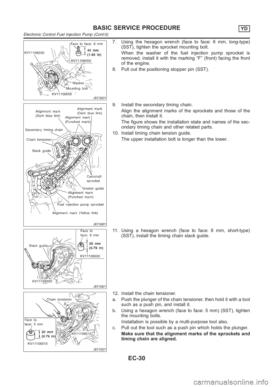
7. Using the hexagon wrench (face to face: 6 mm, long-type)
(SST), tighten the sprocket mounting bolt.
When the washer of the fuel injection pump sprocket is
removed, install it with the marking “F” (front) facing the front
of the engine.
8. Pull out the positioning stopper pin (SST).
JEF368Y
9. Install the secondary timing chain.
Align the alignment marks of the sprockets and those of the
chain, then install it.
The figure shows the installation state and names of the sec-
ondary timing chain and other related parts.
10. Install timing chain tension guide.
The upper installation bolt is longer than the lower.
JEF356Y
11. Using a hexagon wrench (face to face: 6 mm, short-type)
(SST), install the timing chain slack guide.
JEF355Y
12. Install the chain tensioner.
a. Push the plunger of the chain tensioner, then hold it with a tool
such as a push pin, and install it.
b. Using a hexagon wrench (face to face: 5 mm) (SST), tighten
the mounting bolts.
Installation is possible by a multi-purpose tool also.
c. Pull out the tool such as a push pin which holds the plunger.
Make sure that the alignment marks of the sprockets and
timing chain are aligned.
BASIC SERVICE PROCEDUREYD
Electronic Control Fuel Injection Pump (Cont’d)
EC-30
Page 1085 of 3189
JEF369Y
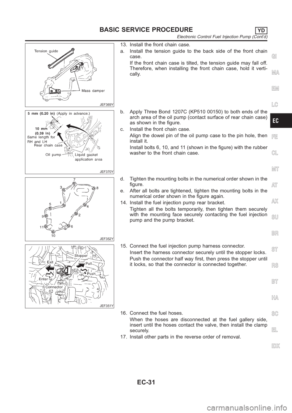
13. Install the front chain case.
a. Install the tension guide to the back side of the front chain
case.
If the front chain case is tilted, the tension guide may fall off.
Therefore, when installing the front chain case, hold it verti-
cally.
JEF370Y
b. Apply Three Bond 1207C (KP510 00150) to both ends of the
arch area of the oil pump (contact surface of rear chain case)
as shown in the figure.
c. Install the front chain case.
Align the dowel pin of the oil pump case to the pin hole, then
install it.
Install bolts 6, 10, and 11 (shown in the figure) with the rubber
washer to the front chain case.
JEF352Y
d. Tighten the mounting bolts in the numerical order shown in the
figure.
e. After all bolts are tightened, tighten the mounting bolts in the
numerical order shown in the figure again.
14. Install the fuel injection pump rear bracket.
Tighten all the bolts temporarily, then tighten them securely
with the mounting face securely contacting the fuel injection
pump and the pump bracket.
JEF351Y
15. Connect the fuel injection pump harness connector.
Insert the harness connector securely until the stopper locks.
Push the connector half way first, then press the stopper until
it locks, so that the connector is connected together.
16. Connect the fuel hoses.
When the hoses are disconnected at the fuel gallery side,
insert until the hoses contact the valve, then install the clamp
securely.
17. Install other parts in the reverse order of removal.
GI
MA
EM
LC
FE
CL
MT
AT
AX
SU
BR
ST
RS
BT
HA
SC
EL
IDX
BASIC SERVICE PROCEDUREYD
Electronic Control Fuel Injection Pump (Cont’d)
EC-31