Page 2075 of 3189
TROUBLE DIAGNOSIS
ATC-95
C
D
E
F
G
H
I
K
L
MA
B
AT C
Insufficient HeatingEJS001ZR
SYMPTOM: Insufficient heating
INSPECTION FLOW
*1ATC-51, "Operational Check"*2ATC-42, "Self-diagnosis Function",
see No.1.*3AT C - 4 2 , "Self-diagnosis Function",
see No.5.
*4ATC-42, "
Self-diagnosis Function",
see No.7.*5ATC-63, "Air Mix Door Motor Circuit"*6AT C - 4 2 , "Self-diagnosis Function",
see No.14.
RJIA1709E
Page 2077 of 3189
TROUBLE DIAGNOSIS
ATC-97
C
D
E
F
G
H
I
K
L
MA
B
AT C
NoiseEJS0022W
SYMPTOM: Noise
INSPECTION FLOW
RJIA1596E
Page 2078 of 3189
ATC-98
TROUBLE DIAGNOSIS
Self-diagnosis
EJS0022X
Symptom: Self-diagnosis cannot be performed.
INSPECTION FLOW
*1ATC-138, "Compressor Clutch"*2ATC-139, "INSTALLATION"*3AT C - 2 0 , "Maintenance of Lubricant
Quantity in Compressor"
*4ATC-51, "Operational Check"*5 QG engine: EM-11, "Checking Drive
Belts"
YD engine: EM-11, "DRIVE BELTS"
*1 EL-11, "POWER SUPPLY ROUT-
ING" *2ATC-109, "
Multiplex Communication
Circuit"
*3AT C - 5 1 , "Operational Check"
*4ATC-29, "SYMPTOM TABLE"
RJIA1710E
Page 2079 of 3189
TROUBLE DIAGNOSIS
ATC-99
C
D
E
F
G
H
I
K
L
MA
B
AT C
Memory FunctionEJS0022Y
Symptom: Memory function does not operate.
INSPECTION FLOW
*1 EL-11, "POWER SUPPLY ROUT-
ING"*2AT C - 5 1 , "Operational Check"*3AT C - 4 2 , "Self-diagnosis Function"
*4AT C - 5 5 , "Power Supply and Ground
Circuit for Auto Amp."
RJIA1711E
Page 2359 of 3189

CEL083
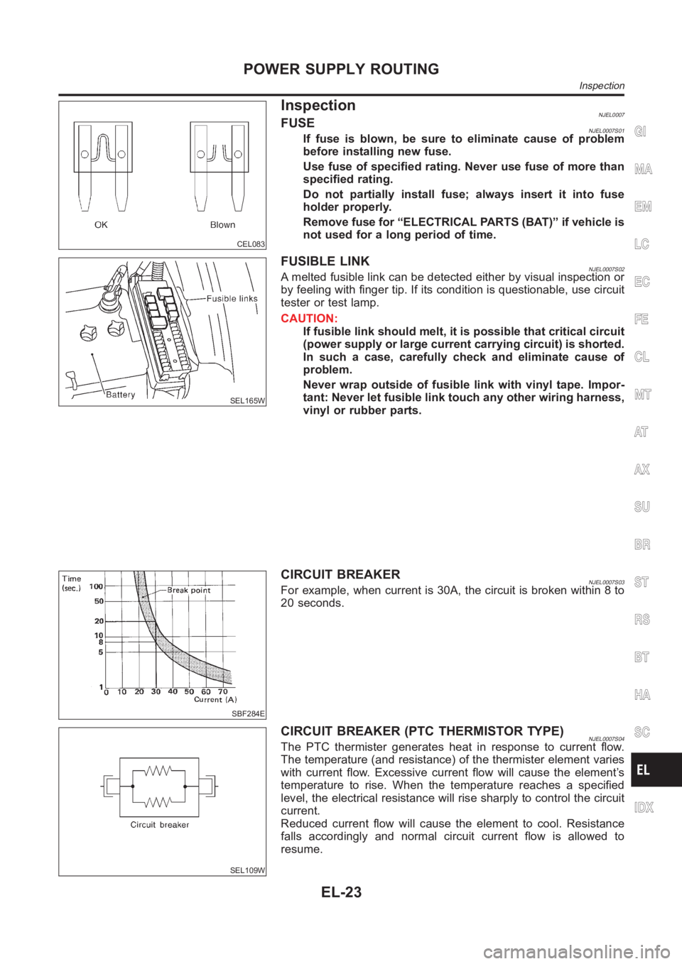
InspectionNJEL0007FUSENJEL0007S01If fuse is blown, be sure to eliminate cause of problem
before installing new fuse.
Use fuse of specified rating. Never use fuse of more than
specified rating.
Do not partially install fuse; always insert it into fuse
holder properly.
Remove fuse for “ELECTRICAL PARTS (BAT)” if vehicle is
not used for a long period of time.
SEL165W
FUSIBLE LINKNJEL0007S02A melted fusible link can be detected either by visual inspection or
by feeling with finger tip. If its condition is questionable, use circuit
tester or test lamp.
CAUTION:
If fusible link should melt, it is possible that critical circuit
(power supply or large current carrying circuit) is shorted.
In such a case, carefully check and eliminate cause of
problem.
Never wrap outside of fusible link with vinyl tape. Impor-
tant: Never let fusible link touch any other wiring harness,
vinyl or rubber parts.
SBF284E
CIRCUIT BREAKERNJEL0007S03For example, when current is 30A, the circuit is broken within 8 to
20 seconds.
SEL109W
CIRCUIT BREAKER (PTC THERMISTOR TYPE)NJEL0007S04The PTC thermister generates heat in response to current flow.
The temperature (and resistance) of the thermister element varies
with current flow. Excessive current flow will cause the element’s
temperature to rise. When the temperature reaches a specified
level, the electrical resistance will rise sharply to control the circuit
current.
Reduced current flow will cause the element to cool. Resistance
falls accordingly and normal circuit current flow is allowed to
resume.
GI
MA
EM
LC
EC
FE
CL
MT
AT
AX
SU
BR
ST
RS
BT
HA
SC
IDX
POWER SUPPLY ROUTING
Inspection
EL-23
Page 2729 of 3189
Trouble Diagnoses/QG and YD Engine Models
with Common Rail
NJEL0590WORK FLOWNJEL0590S01
SEL729WE
GI
MA
EM
LC
EC
FE
CL
MT
AT
AX
SU
BR
ST
RS
BT
HA
SC
IDX
NATS (NISSAN ANTI-THEFT SYSTEM)
Trouble Diagnoses/QG and YD Engine Models with Common Rail
EL-393
Page 2731 of 3189

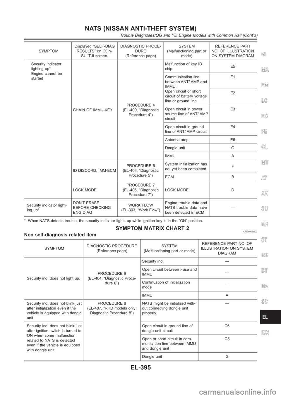
SYMPTOMDisplayed “SELF-DIAG
RESULTS” on CON-
SULT-II screen.DIAGNOSTIC PROCE-
DURE
(Reference page)SYSTEM
(Malfunctioning part or
mode)REFERENCE PART
NO. OF ILLUSTRATION
ON SYSTEM DIAGRAM
Security indicator
lighting up*
Engine cannot be
started
CHAIN OF IMMU-KEYPROCEDURE 4
(EL-400, “Diagnostic
Procedure 4”)Malfunction of key ID
chipE5
Communication line
between ANT/ AMP and
IMMU:
Open circuit or short
circuit of battery voltage
line or ground lineE1
E2
Open circuit in power
source line of ANT/ AMP
circuitE3
Open circuit in ground
line of ANT/ AMP circuitE4
Antenna amp. E6
Dongle unit G
IMMU A
ID DISCORD, IMM-ECMPROCEDURE 5
(EL-403, “Diagnostic
Procedure 5”)System initialization has
not yet been completed.F
ECM B
LOCK MODEPROCEDURE 7
(EL-406, “Diagnostic
Procedure 7”)LOCK MODE D
Security indicator light-
ing up*DON’T ERASE
BEFORE CHECKING
ENG DIAGWORK FLOW
(EL-393, “Work Flow”)Engine trouble data and
NATS trouble data have
been detected in ECM—
*: When NATS detects trouble, the security indicator lights up while ignition key is in the “ON” position.
SYMPTOM MATRIX CHART 2NJEL0590S03Non self-diagnosis related item
SYMPTOMDIAGNOSTIC PROCEDURE
(Reference page)SYSTEM
(Malfunctioning part or mode)REFERENCE PART NO. OF
ILLUSTRATION ON SYSTEM
DIAGRAM
Security ind. does not light up.PROCEDURE 6
(EL-404, “Diagnostic Proce-
dure 6”)Security ind. —
Open circuit between Fuse and
IMMU—
Continuation of initialization
mode—
IMMU A
Security ind. does not blink just
after initialization even if the
vehicle is equipped with dongle
unit.PROCEDURE 8
(EL-407, “RHD models only:
Diagnostic Procedure 8”)NATS might be initialized with-
out connecting dongle unit
properly.—
Security ind. does not blink just
after ignition switch is turned to
ON when some malfunction
related to NATS is detected
even if the vehicle is equipped
with dongle unit.Open circuit in ground line of
dongle unit circuitC6
Open or short circuit in com-
munication line between IMMU
and dongle unitC5
Dongle unit G
GI
MA
EM
LC
EC
FE
CL
MT
AT
AX
SU
BR
ST
RS
BT
HA
SC
IDX
NATS (NISSAN ANTI-THEFT SYSTEM)
Trouble Diagnoses/QG and YD Engine Models with Common Rail (Cont’d)
EL-395
Page 2748 of 3189
Trouble Diagnoses/YD Engine Models without
Common Rail and K9K Engine Models
NJEL0411WORK FLOWNJEL0411S01
SEL729WE
NATS (NISSAN ANTI-THEFT SYSTEM)
Trouble Diagnoses/YD Engine Models without Common Rail and K9K Engine Models
EL-412