2003 NISSAN ALMERA N16 flow
[x] Cancel search: flowPage 2750 of 3189
SYMPTOMDisplayed “SELF-DIAG
RESULTS” on CON-
SULT-II screen.DIAGNOSTIC PROCE-
DURE
(Reference page)SYSTEM
(Malfunctioning part or
mode)REFERENCE PART
NO. OF ILLUSTRATION
ON SYSTEM DIAGRAM
MIL staying ON
Security indicator
lighting up*DON’T ERASE
BEFORE CHECKING
ENG DIAGWORK FLOW
(EL-412)Engine trouble data and
NATS trouble data have
been detected in ECM—
*: When NATS detects trouble, the security indicator lights up while ignition key is in the “ON” position.
*: When the vehicle is equipped with a dongle unit (RHD models for Europe), the security indicator blinks 6 times just after the ignition
switch is turned to ON. Then the security indicator lights up while the ignition key is in the “ON” position.
SYMPTOM MATRIX CHART 2NJEL0411S03(Non self-diagnosis related item)
SYMPTOMDIAGNOSTIC PROCEDURE
(Reference page)SYSTEM
(Malfunctioning part or mode)REFERENCE PART NO. OF
ILLUSTRATION ON SYSTEM
DIAGRAM
Security ind. does not light up.PROCEDURE 6
(EL-424)Security ind. —
Open circuit between Fuse and
IMMU—
Continuation of initialization
mode—
IMMU A
Security ind. does not blink just
after initialization even if the
vehicle is equipped with dongle
unit.
PROCEDURE 8
(EL-428)NATS might be initialized with-
out connecting dongle unit
properly.—
Open circuit in ground line of
dongle unit circuitC6
Security ind. does not blink just
after ignition switch is turned to
ON when some malfunction
related to NATS is detected
even if the vehicle is equipped
with dongle unit.Open or short circuit in com-
munication line between IMMU
and dongle unitC5
Dongle unit G
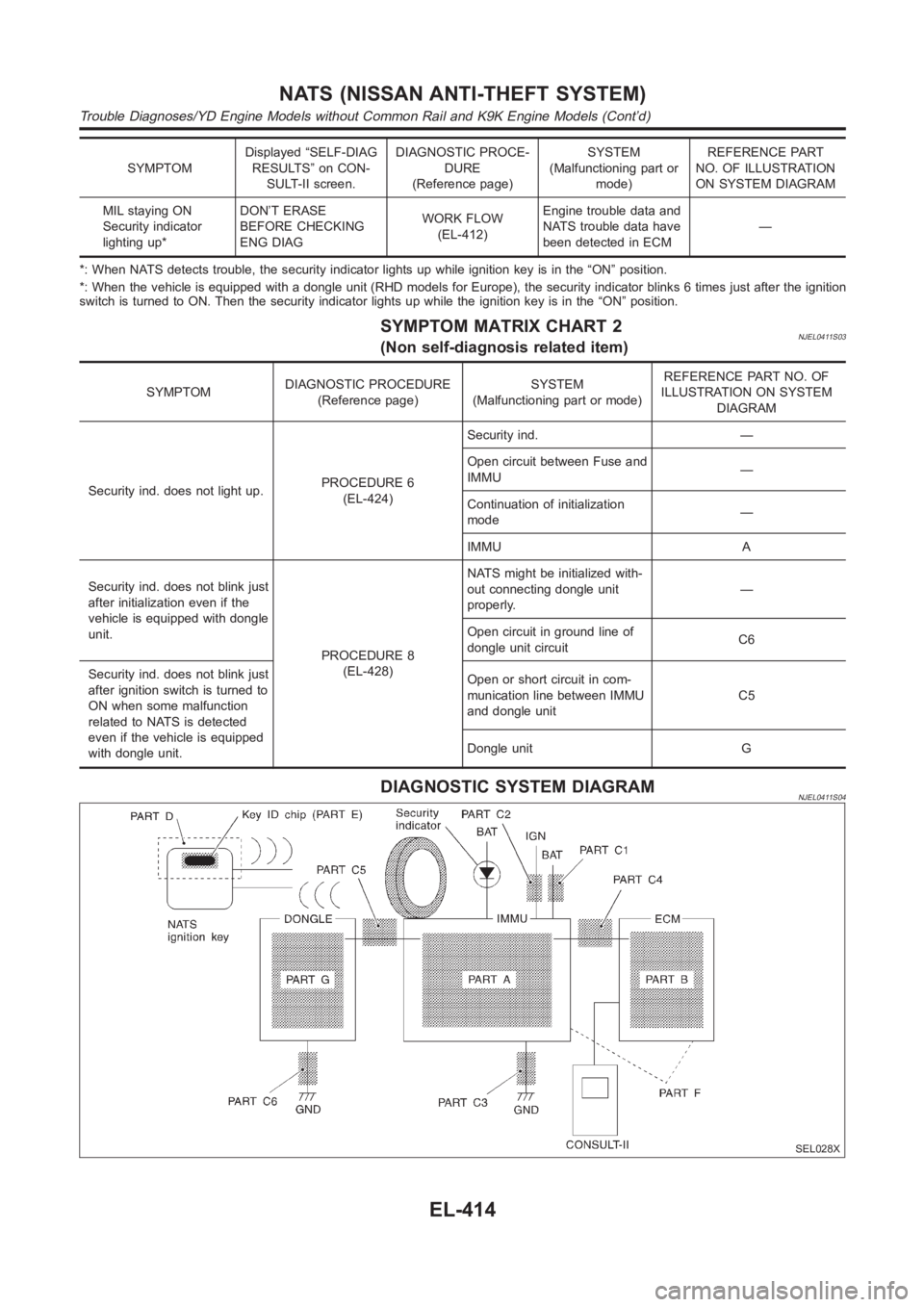
DIAGNOSTIC SYSTEM DIAGRAMNJEL0411S04
SEL028X
NATS (NISSAN ANTI-THEFT SYSTEM)
Trouble Diagnoses/YD Engine Models without Common Rail and K9K Engine Models (Cont’d)
EL-414
Page 2851 of 3189
Trouble DiagnosesNJEL0540WORK FLOWNJEL0540S011. Print all the data of “SELF-DIAG RESULTS” and “DATA MONITOR” for “ENGINE”, “A/T” and “SMART
ENTRANCE” displayed on CONSULT-II. Refer to the following.
“DTC U1000, U1001 CAN COMMUNICATION LINE” (WITH EURO-OBD) (EC-116) for “ENGINE”
“DTC U1000, U1001 CAN COMMUNICATION LINE” (WITHOUT EURO-OBD) (EC-492) for “ENGINE”
“DTC U1000 CAN COMMUNICATION LINE” (WITH EURO-OBD) (AT-192) for “A/T”
“CAN COMMUNICATION LINE” (All) (AT-395) for “A/T”
“CAN Communication Line Check” (EL-380) for “SMART ENTRANCE”
2. Attach the printed sheet of “SELF-DIAG RESULTS” and “DATA MONITOR” ontothe check sheet. Refer
to “CHECK SHEET” (EL-516).
3. Based on the data monitor results, put “v” marks onto the items with “UNKWN” or “NG” in the check sheet
table. Refer to “CHECK SHEET“ (EL-516).
NOTE:
If “NG” is displayed on “CAN COMM” for the diagnosed control unit, replace the control unit.
4. According to the check sheet results (example), start inspection. Refer to “CHECK SHEET RESULTS
(EXAMPLE)” (EL-517).GI
MA
EM
LC
EC
FE
CL
MT
AT
AX
SU
BR
ST
RS
BT
HA
SC
IDX
CAN SYSTEM (TYPE 1)
Trouble Diagnoses
EL-515
Page 2869 of 3189
Trouble DiagnosesNJEL0545WORK FLOWNJEL0545S011. Print all the data of “SELF-DIAG RESULTS” and “DATA MONITOR” for “ENGINE” and “SMART
ENTRANCE” displayed on CONSULT-II. Refer to the following.
“DTC U1000, U1001 CAN COMMUNICATION LINE” (WITH EURO-OBD) (EC-116) for “ENGINE”
“DTC U1000, U1001 CAN COMMUNICATION LINE” (WITHOUT EURO-OBD) (EC-492) for “ENGINE”
“CAN Communication Line Check” (EL-380) for “SMART ENTRANCE”.
2. Attach the printed sheet of “SELF-DIAG RESULTS” and “DATA MONITOR” ontothe check sheet. Refer
to “CHECK SHEET” (EL-534).
3. Based on the data monitor results, put “v” marks onto the items with “UNKWN” or “NG” in the check sheet
table. Refer to “CHECK SHEET” (EL-534).
NOTE:
If “NG” is displayed on “CAN COMM” for the diagnosed control unit, replace the control unit.
4. According to the check sheet results (example), start inspection. Refer to “CHECK SHEET RESULTS
(EXAMPLE)” (EL-535).GI
MA
EM
LC
EC
FE
CL
MT
AT
AX
SU
BR
ST
RS
BT
HA
SC
IDX
CAN SYSTEM (TYPE 2)
Trouble Diagnoses
EL-533
Page 2935 of 3189
NJEL0311
Use the chart below to find out what each wiring
diagram code stands for.
Refer to the wiring diagram code in the alphabetical
index to find the location (page number) of each
wiring diagram.
Code Section Wiring Diagram Name
ISTSIG AT A/T 1ST Signal
2NDSIG AT A/T 2ND Signal
3RDSIG AT A/T 3RD Signal
4THSIG AT A/T 4TH Signal
A/C, M HA Manual Air Conditioner
A/CCUT EC Air Conditioner Cut Control
AAC/V EC IACV-AAC Valve
AACVLV EC IACV-AAC Valve
ABS BR Anti-lock Brake System
APS EC Accelerator Position Sensor
AT/C EC A/T Control
ATCONT EC A/T Control
ATDIAG EC A/T Diagnosis Communication Line
AUDIO EL Audio
BA/FTS AT A/T Fluid Temperature Sensor and
TCM Power Supply
BACK/L EL Back-up Lamp
BRK/SW EC Brake Pedal Position Switch
CHARGE SC Charging System
CHIME EL Warning Chime
CIGAR EL Cigarette Lighter
CKPS EC Crankshaft Position Sensor (POS)
CKPS EC Crankshaft Position Sensor (TDC)
CLOCK EL Clock
COOL/F EC Cooling Fan Control
D/LOCK EL Power Door Lock
DEF EL Rear Window Defogger
DTRL EL Headlamp — With Daytime Light
System
ECMRLY EC ECM Relay
ECTS EC Engine Coolant Temperature Sensor
EGR/TS EC EGR Temperature Sensor
EGRC1 EC EGR Function
EGVC/V EC EGR Volume Control Valve
ENGSS AT Engine Speed Signal
Code Section Wiring Diagram Name
F/FOG EL Front Fog Lamp
F/PUMP EC Fuel Pump
FRO2 EC Front Heated Oxygen Sensor (Non
E-OBD)
FRO2/H EC Front Heated Oxygen Sensor Heater
(Non E-OBD)
FTS AT A/T Fluid Temperature Sensor
FUEL EC Fuel Injection System Function
GLOW EC Glow Control System
H/AIM EL Headlamp Aiming Control System
H/LAMP EL Headlamp
H/SEAT EL Heated Seat
HEATER HA Heater System
HLC EL Headlamp Washer
HORN EL Horn
IATS EC Intake Air Temperature Sensor
IATSEN EC Intake Air Temperature Sensor
IGN/SG EC Ignition Signal
ILL EL Illumination
INJECT EC Injector
INJPMP EC Injection Pump
INT/L EL Spot, Vanity Mirror, Personal and
Trunk Room Lamps
IVC EC Intake Valve Timing Control Solenoid
Valve
IVC/V EC Intake Valve Timing Control Solenoid
Valve
KS EC Knock Sensor
LOAD EC Load Signal
LPSV AT Line Pressure Solenoid Valve
MAFS EC Mass Air Flow Sensor
MAIN AT Main Power Supply and Ground Cir-
cuit
MAIN EC Main Power Supply and Ground Cir-
cuit
METER EL Speedometer, Tachometer, Temp.
and Fuel Gauges
MIL/DL EC MIL and Data Link Connectors
MIRROR EL Door Mirror
MULTI EL Multi-remote Control System
NATS EL Nissan Anti-Theft System
GI
MA
EM
LC
EC
FE
CL
MT
AT
AX
SU
BR
ST
RS
BT
HA
SC
IDX
WIRING DIAGRAM CODES (CELL CODES)
EL-599
Page 2937 of 3189
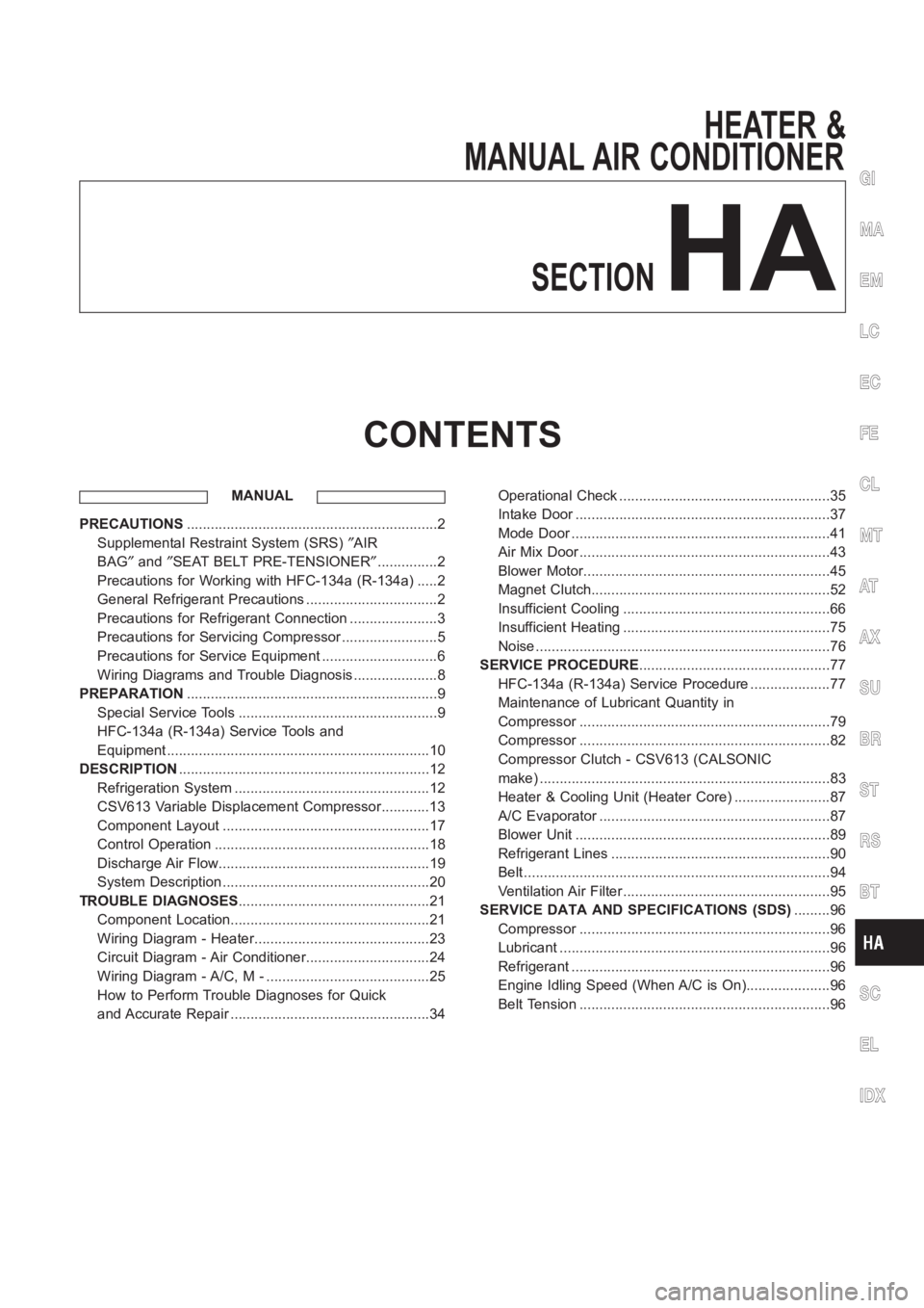
HEATER &
MANUAL AIR CONDITIONER
SECTION
HA
CONTENTS
MANUAL
PRECAUTIONS<0011001100110011001100110011001100110011001100110011001100110011001100110011001100110011001100110011001100110011001100110011001100110011001100110011001100110011001100110011001100110011001100110011001100
11001100110011001100110011001100110011001100110011[2
Supplemental Restraint System (SRS)″AIR
BAG″and″SEAT BELT PRE-TENSIONER″...............2
Precautions for Working with HFC-134a (R-134a) .....2
General Refrigerant Precautions .................................2
Precautions for Refrigerant Connection ......................3
Precautions for Servicing Compressor ........................5
Precautions for Service Equipment .............................6
Wiring Diagrams and Trouble Diagnosis .....................8
PREPARATION<0011001100110011001100110011001100110011001100110011001100110011001100110011001100110011001100110011001100110011001100110011001100110011001100110011001100110011001100110011001100110011001100110011001100
11001100110011001100110011001100110011001100110011[9
Special Service Tools ..................................................9
HFC-134a (R-134a) Service Tools and
Equipment <0011001100110011001100110011001100110011001100110011001100110011001100110011001100110011001100110011001100110011001100110011001100110011001100110011001100110011001100110011001100110011001100110011001100
11001100110011[............10
DESCRIPTION<0011001100110011001100110011001100110011001100110011001100110011001100110011001100110011001100110011001100110011001100110011001100110011001100110011001100110011001100110011001100110011001100110011001100
11001100110011001100110011001100110011001100110011[12
Refrigeration System .................................................12
CSV613 Variable Displacement Compressor............13
Component Layout ....................................................17
Control Operation ......................................................18
Discharge Air Flow.....................................................19
System Description ....................................................20
TROUBLE DIAGNOSES................................................21
Component Location..................................................21
Wiring Diagram - Heater............................................23
Circuit Diagram - Air Conditioner...............................24
Wiring Diagram - A/C, M - .........................................25
How to Perform Trouble Diagnoses for Quick
and Accurate Repair ..................................................34Operational Check .....................................................35
Intake Door <0011001100110011001100110011001100110011001100110011001100110011001100110011001100110011001100110011001100110011001100110011001100110011001100110011001100110011001100110011001100110011001100110011001100
1100110011[...........37
Mode Door <0011001100110011001100110011001100110011001100110011001100110011001100110011001100110011001100110011001100110011001100110011001100110011001100110011001100110011001100110011001100110011001100110011001100
110011001100110011[..........41
Air Mix Door <0011001100110011001100110011001100110011001100110011001100110011001100110011001100110011001100110011001100110011001100110011001100110011001100110011001100110011001100110011001100110011001100110011001100
1100110011[..........43
Blower Motor<0011001100110011001100110011001100110011001100110011001100110011001100110011001100110011001100110011001100110011001100110011001100110011001100110011001100110011001100110011001100110011001100110011001100
110011[..........45
Magnet Clutch<0011001100110011001100110011001100110011001100110011001100110011001100110011001100110011001100110011001100110011001100110011001100110011001100110011001100110011001100110011001100110011001100110011001100
11[.........52
Insufficient Cooling ....................................................66
Insufficient Heating ....................................................75
Noise <0011001100110011001100110011001100110011001100110011001100110011001100110011001100110011001100110011001100110011001100110011001100110011001100110011001100110011001100110011001100110011001100110011001100
110011001100110011001100110011[................76
SERVICE PROCEDURE................................................77
HFC-134a (R-134a) Service Procedure ....................77
Maintenance of Lubricant Quantity in
Compressor <0011001100110011001100110011001100110011001100110011001100110011001100110011001100110011001100110011001100110011001100110011001100110011001100110011001100110011001100110011001100110011001100110011001100
1100110011[..........79
Compressor <0011001100110011001100110011001100110011001100110011001100110011001100110011001100110011001100110011001100110011001100110011001100110011001100110011001100110011001100110011001100110011001100110011001100
1100110011[..........82
Compressor Clutch - CSV613 (CALSONIC
make) <0011001100110011001100110011001100110011001100110011001100110011001100110011001100110011001100110011001100110011001100110011001100110011001100110011001100110011001100110011001100110011001100110011001100
110011001100110011001100110011[...............83
Heater & Cooling Unit (Heater Core) ........................87
A/C Evaporator ..........................................................87
Blower Unit <0011001100110011001100110011001100110011001100110011001100110011001100110011001100110011001100110011001100110011001100110011001100110011001100110011001100110011001100110011001100110011001100110011001100
1100110011[...........89
Refrigerant Lines .......................................................90
Belt <0011001100110011001100110011001100110011001100110011001100110011001100110011001100110011001100110011001100110011001100110011001100110011001100110011001100110011001100110011001100110011001100110011001100
1100110011001100110011001100110011[..................94
Ventilation Air Filter ....................................................95
SERVICE DATA AND SPECIFICATIONS (SDS).........96
Compressor <0011001100110011001100110011001100110011001100110011001100110011001100110011001100110011001100110011001100110011001100110011001100110011001100110011001100110011001100110011001100110011001100110011001100
1100110011[..........96
Lubricant <0011001100110011001100110011001100110011001100110011001100110011001100110011001100110011001100110011001100110011001100110011001100110011001100110011001100110011001100110011001100110011001100110011001100
11001100110011[..............96
Refrigerant <0011001100110011001100110011001100110011001100110011001100110011001100110011001100110011001100110011001100110011001100110011001100110011001100110011001100110011001100110011001100110011001100110011001100
110011[.............96
Engine Idling Speed (When A/C is On).....................96
Belt Tension <0011001100110011001100110011001100110011001100110011001100110011001100110011001100110011001100110011001100110011001100110011001100110011001100110011001100110011001100110011001100110011001100110011001100
110011[...........96
GI
MA
EM
LC
EC
FE
CL
MT
AT
AX
SU
BR
ST
RS
BT
SC
EL
IDX
Page 2943 of 3189
RHA273D
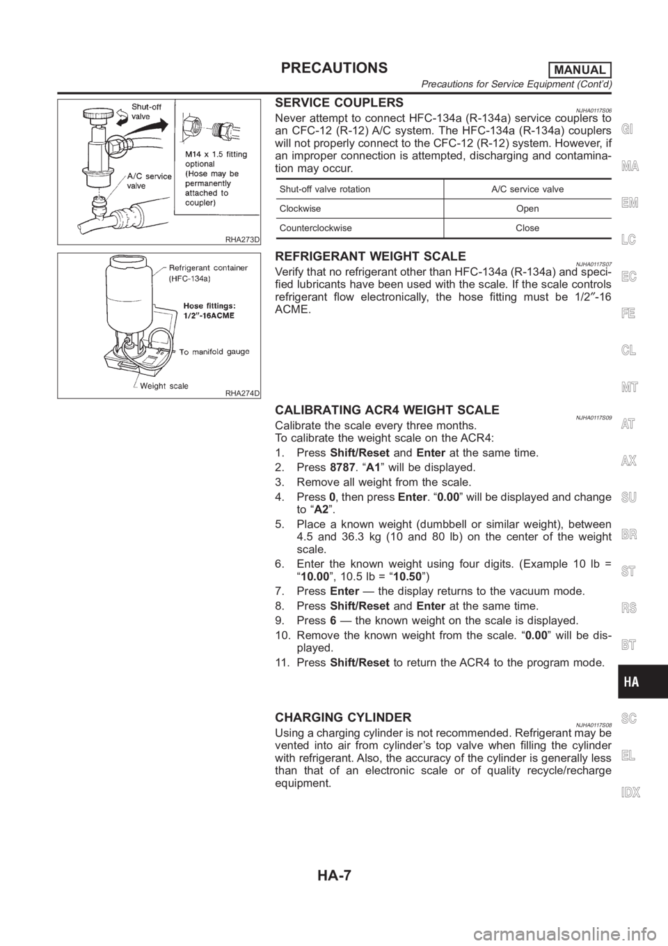
SERVICE COUPLERSNJHA0117S06Never attempt to connect HFC-134a (R-134a) service couplers to
an CFC-12 (R-12) A/C system. The HFC-134a (R-134a) couplers
will not properly connect to the CFC-12 (R-12) system. However, if
an improper connection is attempted, discharging and contamina-
tion may occur.
Shut-off valve rotation A/C service valve
Clockwise Open
Counterclockwise Close
RHA274D
REFRIGERANT WEIGHT SCALENJHA0117S07Verify that no refrigerant other than HFC-134a (R-134a) and speci-
fied lubricants have been used with the scale. If the scale controls
refrigerant flow electronically, the hose fitting must be 1/2″-16
ACME.
CALIBRATING ACR4 WEIGHT SCALENJHA0117S09Calibrate the scale every three months.
To calibrate the weight scale on the ACR4:
1. PressShift/ResetandEnterat the same time.
2. Press8787.“A1” will be displayed.
3. Remove all weight from the scale.
4. Press0, then pressEnter.“0.00” will be displayed and change
to “A2”.
5. Place a known weight (dumbbell or similar weight), between
4.5 and 36.3 kg (10 and 80 lb) on the center of the weight
scale.
6. Enter the known weight using four digits. (Example 10 lb =
“10.00”, 10.5 lb = “10.50”)
7. PressEnter— the display returns to the vacuum mode.
8. PressShift/ResetandEnterat the same time.
9. Press6— the known weight on the scale is displayed.
10. Remove the known weight from the scale. “0.00” will be dis-
played.
11. PressShift/Resetto return the ACR4 to the program mode.
CHARGING CYLINDERNJHA0117S08Using a charging cylinder is not recommended. Refrigerant may be
vented into air from cylinder’s top valve when filling the cylinder
with refrigerant. Also, the accuracy of the cylinder is generally less
than that of an electronic scale or of quality recycle/recharge
equipment.
GI
MA
EM
LC
EC
FE
CL
MT
AT
AX
SU
BR
ST
RS
BT
SC
EL
IDX
PRECAUTIONSMANUAL
Precautions for Service Equipment (Cont’d)
HA-7
Page 2948 of 3189
Refrigeration System
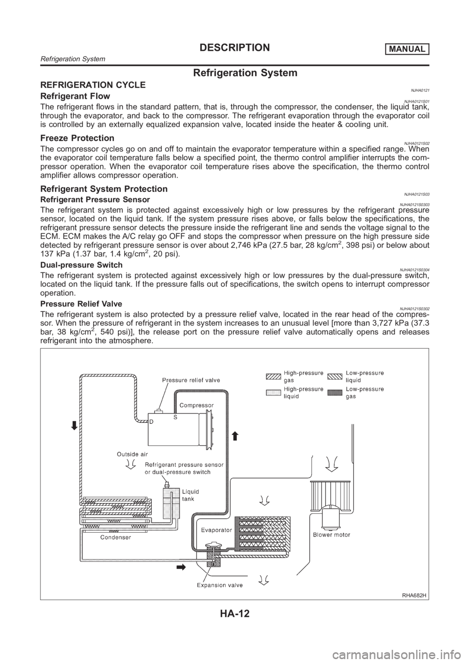
REFRIGERATION CYCLENJHA0121Refrigerant FlowNJHA0121S01The refrigerant flows in the standard pattern, that is, through the compressor, the condenser, the liquid tank,
through the evaporator, and back to the compressor. The refrigerant evaporation through the evaporator coil
is controlled by an externally equalized expansion valve, located insidethe heater & cooling unit.
Freeze ProtectionNJHA0121S02The compressor cycles go on and off to maintain the evaporator temperaturewithin a specified range. When
the evaporator coil temperature falls below a specified point, the thermocontrol amplifier interrupts the com-
pressor operation. When the evaporator coil temperature rises above the specification, the thermo control
amplifier allows compressor operation.
Refrigerant System ProtectionNJHA0121S03Refrigerant Pressure SensorNJHA0121S0303The refrigerant system is protected against excessively high or low pressures by the refrigerant pressure
sensor, located on the liquid tank. If the system pressure rises above, or falls below the specifications, the
refrigerant pressure sensor detects the pressure inside the refrigerantline and sends the voltage signal to the
ECM. ECM makes the A/C relay go OFF and stops the compressor when pressure onthe high pressure side
detected by refrigerant pressure sensor is over about 2,746 kPa (27.5 bar,28 kg/cm
2, 398 psi) or below about
137 kPa (1.37 bar, 1.4 kg/cm2, 20 psi).
Dual-pressure Switch
NJHA0121S0304The refrigerant system is protected against excessively high or low pressures by the dual-pressure switch,
located on the liquid tank. If the pressure falls out of specifications, the switch opens to interrupt compressor
operation.
Pressure Relief Valve
NJHA0121S0302The refrigerant system is also protected by a pressure relief valve, located in the rear head of the compres-
sor. When the pressure of refrigerant in the system increases to an unusuallevel [more than 3,727 kPa (37.3
bar, 38 kg/cm
2, 540 psi)], the release port on the pressure relief valve automatically opens and releases
refrigerant into the atmosphere.
RHA682H
DESCRIPTIONMANUAL
Refrigeration System
HA-12
Page 2954 of 3189
Control OperationNJHA0123
RHA247I
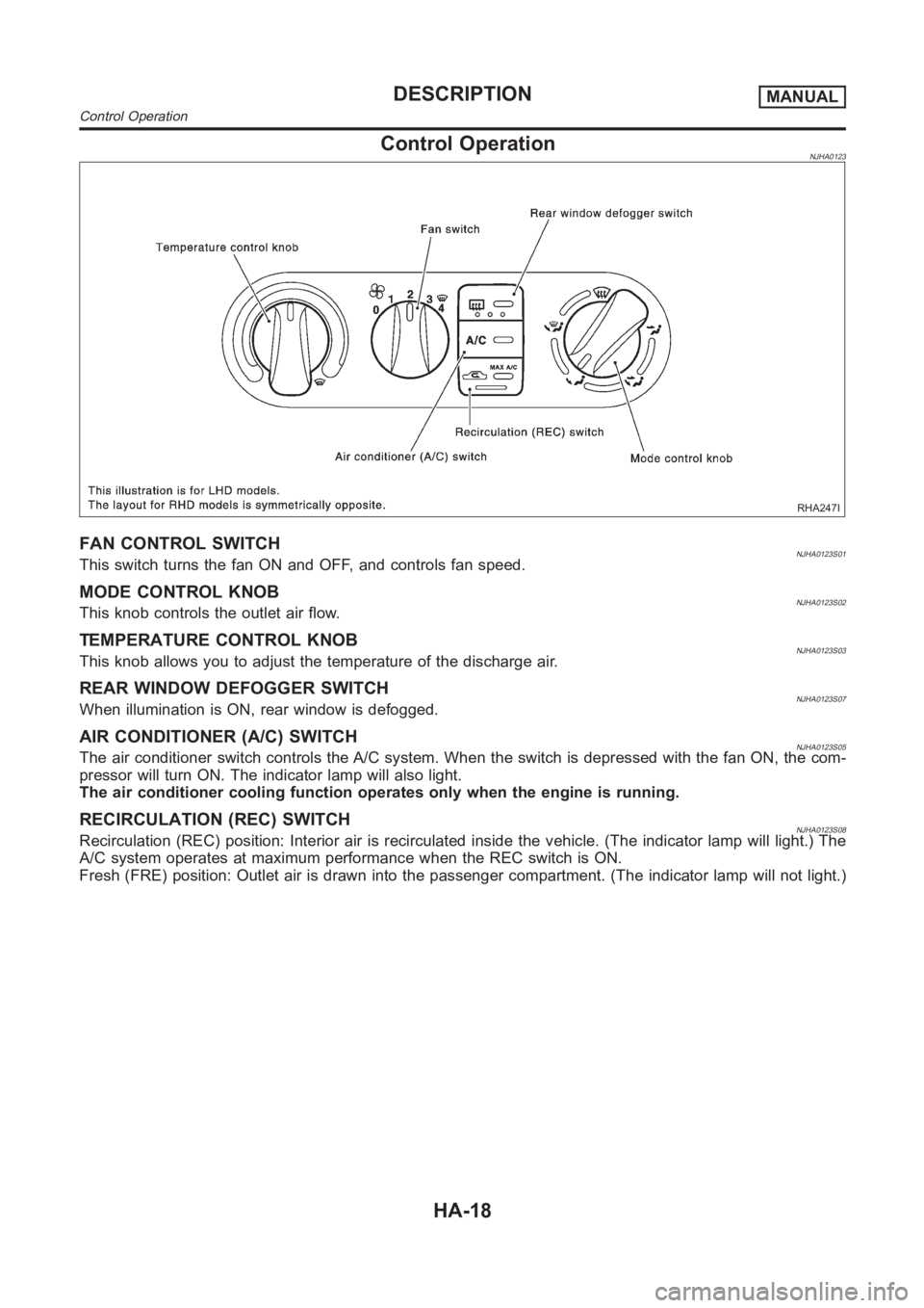
FAN CONTROL SWITCHNJHA0123S01This switch turns the fan ON and OFF, and controls fan speed.
MODE CONTROL KNOBNJHA0123S02This knob controls the outlet air flow.
TEMPERATURE CONTROL KNOBNJHA0123S03This knob allows you to adjust the temperature of the discharge air.
REAR WINDOW DEFOGGER SWITCHNJHA0123S07When illumination is ON, rear window is defogged.
AIR CONDITIONER (A/C) SWITCHNJHA0123S05The air conditioner switch controls the A/C system. When the switch is depressed with the fan ON, the com-
pressor will turn ON. The indicator lamp will also light.
The air conditioner cooling function operates only when the engine is running.
RECIRCULATION (REC) SWITCHNJHA0123S08Recirculation (REC) position: Interior air is recirculated inside the vehicle. (The indicator lamp will light.) The
A/C system operates at maximum performance when the REC switch is ON.
Fresh (FRE) position: Outlet air is drawn into the passenger compartment.(The indicator lamp will not light.)
DESCRIPTIONMANUAL
Control Operation
HA-18