2003 NISSAN ALMERA N16 flow
[x] Cancel search: flowPage 3118 of 3189
![NISSAN ALMERA N16 2003 Electronic Repair Manual Fig. 6 INITIAL CHARGING CURRENT SETTING AND CHARGING TIME (Quick charge)
BATTERY
TYPE
28B19R(L)
34B19R(L)
46B24R(L)
55B24R(L)
50D23R(L)
55D23R(L)
65D26R(L)
80D26R(L)
025 [YUASA type code]
027 [YUASA t NISSAN ALMERA N16 2003 Electronic Repair Manual Fig. 6 INITIAL CHARGING CURRENT SETTING AND CHARGING TIME (Quick charge)
BATTERY
TYPE
28B19R(L)
34B19R(L)
46B24R(L)
55B24R(L)
50D23R(L)
55D23R(L)
65D26R(L)
80D26R(L)
025 [YUASA type code]
027 [YUASA t](/manual-img/5/57350/w960_57350-3117.png)
Fig. 6 INITIAL CHARGING CURRENT SETTING AND CHARGING TIME (Quick charge)
BATTERY
TYPE
28B19R(L)
34B19R(L)
46B24R(L)
55B24R(L)
50D23R(L)
55D23R(L)
65D26R(L)
80D26R(L)
025 [YUASA type code]
027 [YUASA type code]
063 [YUASA type code]
067 [YUASA type code]
096 [YUASA type code]
065 [YUASA type code]
075 [YUASA type code]
096L [YUASA type code]
010S [YUASA type code]
75D31R(L)
95D31R(L)
115D31R(L)
110D26R(L)
95E41R(L)
130E41R(L)
CURRENT
[A]10 (A) 15 (A) 20 (A) 25 (A) 30 (A)40
(A)
CONVERTED SPECIFIC GRAVITY
1.100 -
1.1302.5 hours
1.130 -
1.1602.0 hours
1.160 -
1.1901.5 hours
1.190 -
1.2201.0 hours
Above
1.2200.75 hours (45 min.)
Check battery type and determine the specified current using the table shown above.
After starting charging, adjustment of charging current is not necessary.
CAUTION:
Do not use quick charge method on a battery whose specific gravity is less than 1.100.
Set initial charging current to value specified in Fig. 6. If charger is notcapable of producing
specified current value, set its charging current as close to that value aspossible.
Keep battery away from open flame while it is being charged.
When connecting charger, connect leads first, then turn on charger. Do notturn on charger first,
as this may cause a spark.
Be careful of a rise in battery temperature because a large current flow is required during quick-
charge operation.
If battery temperature rises above 60°C (140°F), stop charging. Always charge battery when its
temperature is below 60°C (140°F).
Do not exceed the charging time specified in Fig. 6, because charging battery over the charging
time can cause deterioration of the battery.
BATTERY
Battery Test and Charging Chart (Cont’d)
SC-12
Page 3153 of 3189
SST834-I
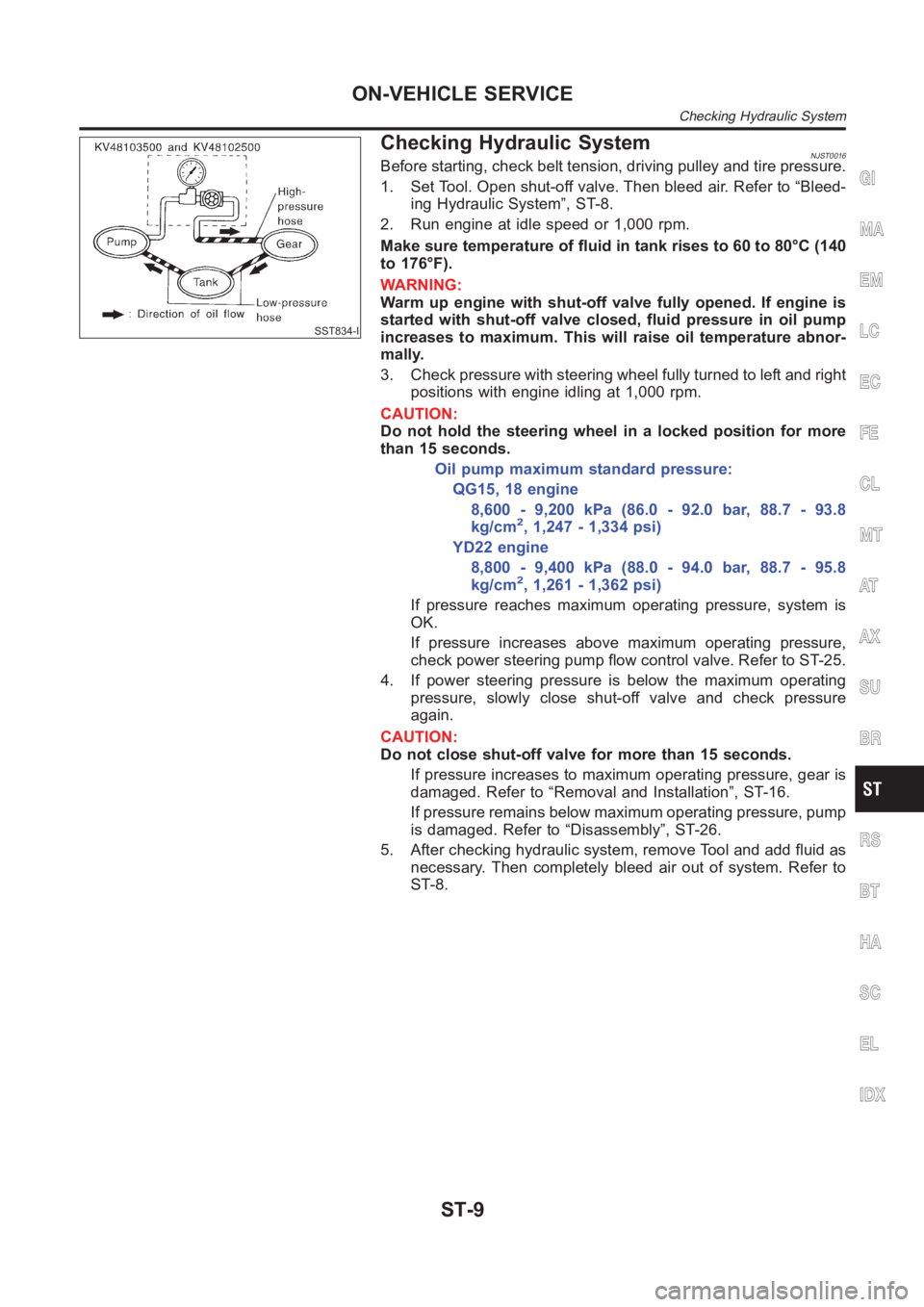
Checking Hydraulic SystemNJST0016Before starting, check belt tension, driving pulley and tire pressure.
1. Set Tool. Open shut-off valve. Then bleed air. Refer to “Bleed-
ing Hydraulic System”, ST-8.
2. Run engine at idle speed or 1,000 rpm.
Make sure temperature of fluid in tank rises to 60 to 80°C (140
to 176°F).
WARNING:
Warm up engine with shut-off valve fully opened. If engine is
started with shut-off valve closed, fluid pressure in oil pump
increases to maximum. This will raise oil temperature abnor-
mally.
3. Check pressure with steering wheel fully turned to left and right
positions with engine idling at 1,000 rpm.
CAUTION:
Do not hold the steering wheel in a locked position for more
than 15 seconds.
Oil pump maximum standard pressure:
QG15, 18 engine
8,600 - 9,200 kPa (86.0 - 92.0 bar, 88.7 - 93.8
kg/cm
2, 1,247 - 1,334 psi)
YD22 engine
8,800 - 9,400 kPa (88.0 - 94.0 bar, 88.7 - 95.8
kg/cm
2, 1,261 - 1,362 psi)
If pressure reaches maximum operating pressure, system is
OK.
If pressure increases above maximum operating pressure,
check power steering pump flow control valve. Refer to ST-25.
4. If power steering pressure is below the maximum operating
pressure, slowly close shut-off valve and check pressure
again.
CAUTION:
Do not close shut-off valve for more than 15 seconds.
If pressure increases to maximum operating pressure, gear is
damaged. Refer to “Removal and Installation”, ST-16.
If pressure remains below maximum operating pressure, pump
is damaged. Refer to “Disassembly”, ST-26.
5. After checking hydraulic system, remove Tool and add fluid as
necessary. Then completely bleed air out of system. Refer to
ST-8.
GI
MA
EM
LC
EC
FE
CL
MT
AT
AX
SU
BR
RS
BT
HA
SC
EL
IDX
ON-VEHICLE SERVICE
Checking Hydraulic System
ST-9
Page 3169 of 3189
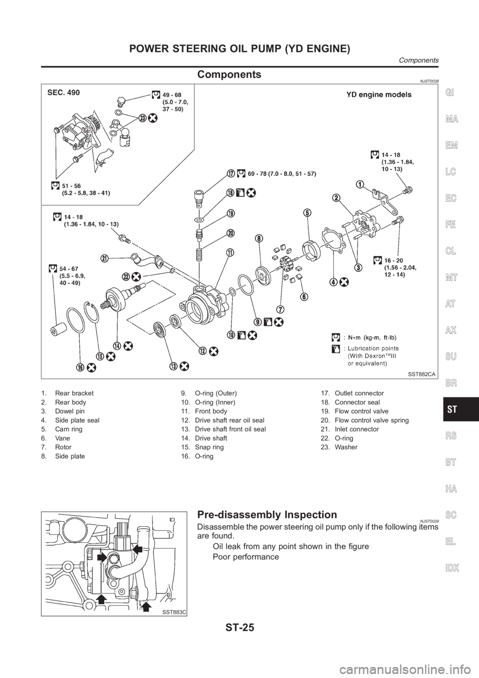
ComponentsNJST0038
SST882CA
1. Rear bracket
2. Rear body
3. Dowel pin
4. Side plate seal
5. Cam ring
6. Vane
7. Rotor
8. Side plate9. O-ring (Outer)
10. O-ring (Inner)
11. Front body
12. Drive shaft rear oil seal
13. Drive shaft front oil seal
14. Drive shaft
15. Snap ring
16. O-ring17. Outlet connector
18. Connector seal
19. Flow control valve
20. Flow control valve spring
21. Inlet connector
22. O-ring
23. Washer
SST883C
Pre-disassembly InspectionNJST0039Disassemble the power steering oil pump only if the following items
are found.
Oil leak from any point shown in the figure
Poor performance
GI
MA
EM
LC
EC
FE
CL
MT
AT
AX
SU
BR
RS
BT
HA
SC
EL
IDX
POWER STEERING OIL PUMP (YD ENGINE)
Components
ST-25
Page 3171 of 3189
SST887C
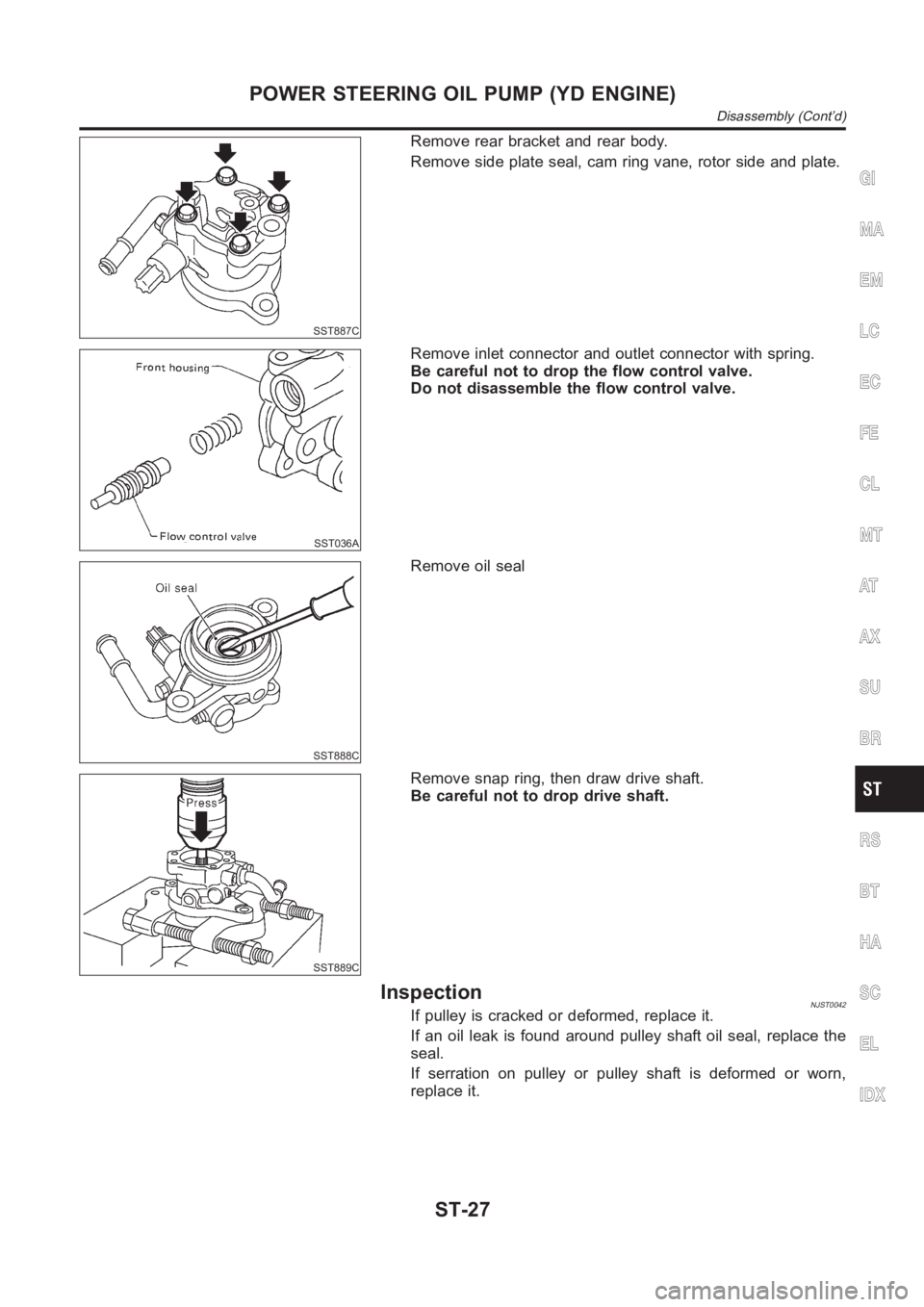
Remove rear bracket and rear body.
Remove side plate seal, cam ring vane, rotor side and plate.
SST036A
Remove inlet connector and outlet connector with spring.
Be careful not to drop the flow control valve.
Do not disassemble the flow control valve.
SST888C
Remove oil seal
SST889C
Remove snap ring, then draw drive shaft.
Be careful not to drop drive shaft.
InspectionNJST0042If pulley is cracked or deformed, replace it.
If an oil leak is found around pulley shaft oil seal, replace the
seal.
If serration on pulley or pulley shaft is deformed or worn,
replace it.
GI
MA
EM
LC
EC
FE
CL
MT
AT
AX
SU
BR
RS
BT
HA
SC
EL
IDX
POWER STEERING OIL PUMP (YD ENGINE)
Disassembly (Cont’d)
ST-27
Page 3176 of 3189
A
A/C air flow (manual A/C) ..............................HA-19
A/C air flow <0011001100110011001100110011001100110011001100110011001100110011001100110011001100110011001100110011001100110011001100110011001100110011001100110011001100110011001100110011001100110011001100110011001100
110024>�TC-27
A/C component layout (manual A/C) .............HA-17
A/C compressor clutch removal and
installation (manual A/C).............................HA-82
A/C compressor clutch removal and
installation ...............................................ATC-139
A/C compressor precaution (manual
A/C) <0011001100110011001100110011001100110011001100110011001100110011001100110011001100110011001100110011001100110011001100110011001100110011001100110011001100110011001100110011001100110011001100110011001100
1100110011001100110011001100110011[....HA-5
A/C compressor precaution ............................ATC-7
A/C compressor special service tool
(manual A/C) .................................................HA-9
A/C compressor special service tool ............ATC-11
A/C control linkage adjustment (manual
A/C) <0011001100110011001100110011001100110011001100110011001100110011001100110011001100110011001100110011001100110011001100110011001100110011001100110011001100110011001100110011001100110011001100110011001100
1100110011001100110011001100110011[..HA-42
A/C control operation (manual A/C) ...............HA-18
A/C diagnostic work flow (manual A/C)..........HA-34
A/C evaporator (manual A/C) .........................HA-87
A/C HFC134a (R134a) system precau-
tion (manual A/C) ..........................................HA-2
A/C HFC134a (R134a) system
precaution <0011001100110011001100110011001100110011001100110011001100110011001100110011001100110011001100110011001100110011001100110011001100110011001100110011001100110011001100110011001100110011001100110011001100
110024>�TC-4
A/C HFC134a (R134a) system service
procedure (manual A/C) .............................HA-77
A/C HFC134a (R134a) system service
procedure ................................................ATC-133
A/C HFC134a (R134a) system service
tools (manual A/C) ......................................HA-10
A/C HFC134a (R134a) system service
tools<0011001100110011001100110011001100110011001100110011001100110011001100110011001100110011001100110011001100110011001100110011001100110011001100110011001100110011001100110011001100110011001100110011001100
110011001100110011001100110011[.ATC-11
A/C HFC134a system service equip-
ment precaution (manual A/C)......................HA-6
A/C HFC134a system service equip-
ment precaution ..........................................ATC-7
A/C lubricant (R134a) (manual A/C) ..............HA-79
A/C lubricant (R134a) ...................................ATC-20
A/C lubrication oil .......................................ATC-150
A/C operational check (manual A/C)..............HA-35
A/C operational check ..................................ATC-51
A/C performance chart (manual A/C).............HA-69
A/C performance test diagnoses
(manual A/C) ...............................................HA-67
A/C performance test diagnoses ..................ATC-89
A/C relay (manual A/C) ..................................HA-65
A/C reray <0011001100110011001100110011001100110011001100110011001100110011001100110011001100110011001100110011001100110011001100110011001100110011001100110011001100110011001100110011001100110011001100110011001100
110011001100110024[TC-85
A/C self-diagnoses (auto A/C) ......................ATC-42
A/C service data specification (manual
A/C) <0011001100110011001100110011001100110011001100110011001100110011001100110011001100110011001100110011001100110011001100110011001100110011001100110011001100110011001100110011001100110011001100110011001100
1100110011001100110011001100110011[..HA-96
A/C service data specification ....................ATC-150
A/C switch (manual A/C) ................................HA-65
A/C system description (auto A/C) ...............ATC-22
A/C trouble diagnoses (auto A/C) ................ATC-29
A/C, A - Wiring diagram................................ATC-33
A/C, M - Wiring diagram (manual A/C) ..........HA-25
A/CCUT - Wiring diagram (YD engine) ........EC-212
A/T - Wiring diagram - AT - FTS ...................AT-120
A/T - Wiring diagram - AT - MAIN .................AT-341A/T - Wiring diagram - AT - PNP/SW ............AT-114
A/T - Wiring diagram - AT -
VSS A/T........................................AT-127, AT-346
A/T fluid checking ............................................AT-13
A/T fluid replacement ......................................AT-13
A/T fluid temperature sensor.........................AT-123
A/T shift lock system - Wiring diagram .........AT-400
A/T shift lock system .....................................AT-399
A/T trouble diagnoses ........................AT-56, AT-256
A/T Wiring diagram - AT -
ENG SS........................................AT-131, AT-386
A/T Wiring diagram AT - 1ST ........................AT-137
A/T Wiring diagram AT - 2ND .......................AT-143
A/T Wiring diagram AT - 3RD .......................AT-149
A/T Wiring diagram AT - 4TH ........................AT-155
A/T Wiring diagram AT - BA/FTS.....AT-198, AT-380
A/T Wiring diagram AT - LPSV ........AT-167, AT-391
A/T Wiring diagram AT - OVRCSV ..AT-190, AT-370
A/T Wiring diagram AT - SSV/A.......AT-174, AT-360
A/T Wiring diagram AT - SSV/B.......AT-179, AT-365
A/T Wiring diagram AT - TCV ..........AT-162, AT-375
A/T Wiring diagram AT - TPS ..........AT-185, AT-355
A/T Wiring diagrawm AT -
VSSMTR ......................................AT-204, AT-351
ABS (anti-lock brake system).........................BR-45
ABS - Wiring diagram ....................................BR-50
ABS sensor rotor ............................................AX-24
Accelerator control system .........................FE-3, 14
Accelerator pedal position (APP) sen-
sor (QG engine) ..........EC-212, EC-219, EC-346,
EC-538, EC-545, EC-619
Accelerator pedal released position
learning (QG engine)....................EC-31, EC-426
Accelerator position sensor
(YD engine).................................................EC-89
Air bag disposal..............................................RS-35
Air bag precautions ...........................................GI-3
Air bag <0011001100110011001100110011001100110011001100110011001100110011001100110011001100110011001100110011001100110011001100110011001100110011001100110011001100110011001100110011001100110011001100110011001100
11001100110011001100110011[...RS-20
Air bleeding (hydraulic clutch) ........................CL-10
Air bleeding for brake system ..........................BR-8
Air cleaner and air duct (QG engine) ............EM-14
Air cleaner filter (QG engine).........................EM-14
Air conditioner cut control
(QG engine)..................................EC-26, EC-421
Air conditioner cut control (YD engine) ..........EC-19
Air flow meter - See Mass air flow sen-
sor (QG engine) .........................EC-135, EC-497
Air flow meter - See Mass air flow sen-
sor (YD engine) ..........................................EC-78
Air mix door control linkage adjustment
(manual A/C) ...............................................HA-44
Air mix door control linkage
adjustment ................................ATC-65, ATC-127
Air mix. door motor.......................ATC-63, ATC-127
Air spoiler, rear................................................BT-47
Alternator <0011001100110011001100110011001100110011001100110011001100110011001100110011001100110011001100110011001100110011001100110011001100110011001100110011001100110011001100110011001100110011001100110011001100
1100110011[...SC-30
Ambient sensor...........ATC-101, ATC-103, ATC-116
Angular tightening application
(QG engine)..................................................EM-3
Angular tightening application
(YD engine) ..................................................EM-3
ALPHABETICAL INDEX
IDX-2
Page 3181 of 3189
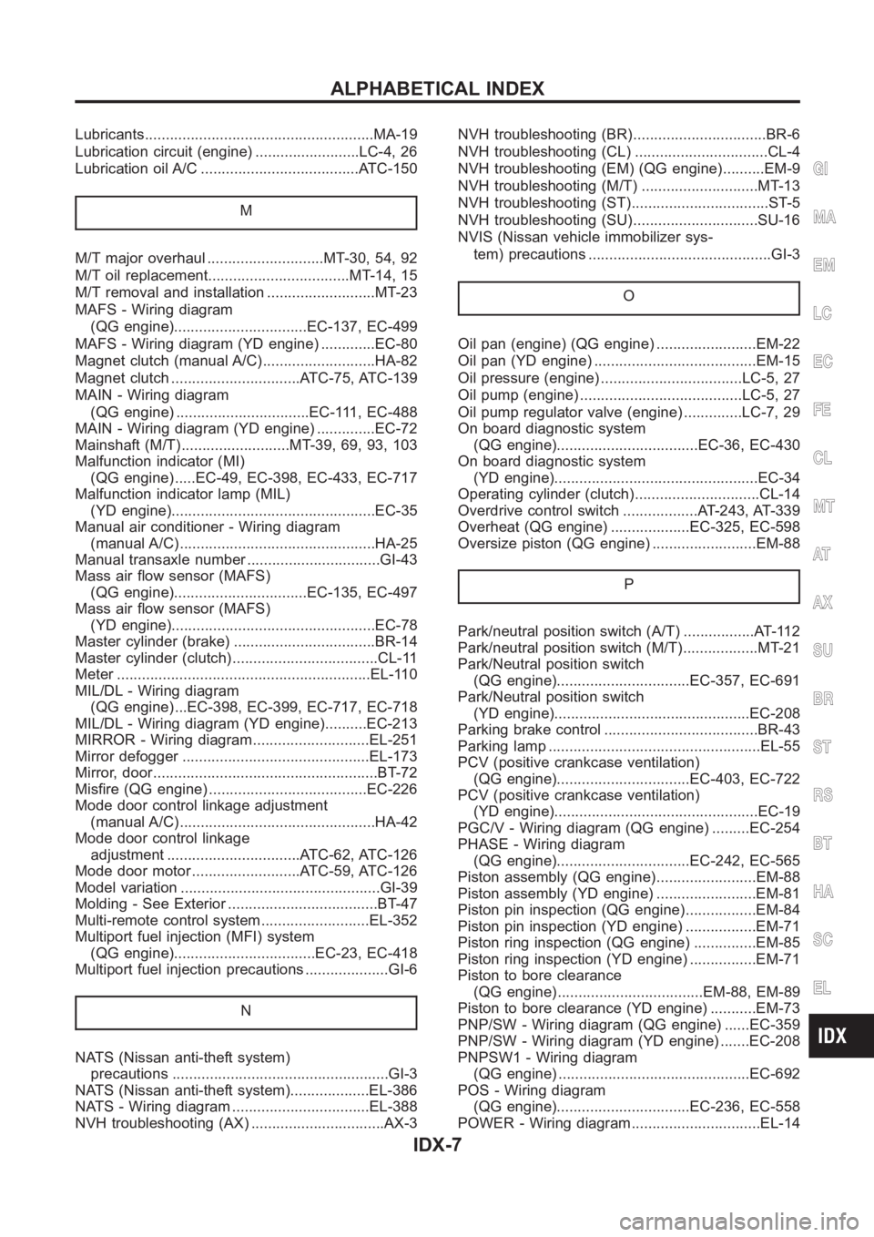
Lubricants<0011001100110011001100110011001100110011001100110011001100110011001100110011001100110011001100110011001100110011001100110011001100110011001100110011001100110011001100110011001100110011001100110011001100
1100110011[..MA-19
Lubrication circuit (engine) .........................LC-4, 26
Lubrication oil A/C ......................................ATC-150
M
M/T major overhaul ............................MT-30, 54, 92
M/T oil replacement..................................MT-14, 15
M/T removal and installation ..........................MT-23
MAFS - Wiring diagram
(QG engine)................................EC-137, EC-499
MAFS - Wiring diagram (YD engine) .............EC-80
Magnet clutch (manual A/C)...........................HA-82
Magnet clutch ...............................ATC-75, ATC-139
MAIN - Wiring diagram
(QG engine) ................................EC-111, EC-488
MAIN - Wiring diagram (YD engine) ..............EC-72
Mainshaft (M/T)..........................MT-39, 69, 93, 103
Malfunction indicator (MI)
(QG engine) .....EC-49, EC-398, EC-433, EC-717
Malfunction indicator lamp (MIL)
(YD engine).................................................EC-35
Manual air conditioner - Wiring diagram
(manual A/C) ...............................................HA-25
Manual transaxle number ................................GI-43
Mass air flow sensor (MAFS)
(QG engine)................................EC-135, EC-497
Mass air flow sensor (MAFS)
(YD engine).................................................EC-78
Master cylinder (brake) ..................................BR-14
Master cylinder (clutch) ...................................CL-11
Meter <0011001100110011001100110011001100110011001100110011001100110011001100110011001100110011001100110011001100110011001100110011001100110011001100110011001100110011001100110011001100110011001100110011001100
110011001100110011001100110011[...EL-110
MIL/DL - Wiring diagram
(QG engine) ...EC-398, EC-399, EC-717, EC-718
MIL/DL - Wiring diagram (YD engine)..........EC-213
MIRROR - Wiring diagram............................EL-251
Mirror defogger .............................................EL-173
Mirror, door<0011001100110011001100110011001100110011001100110011001100110011001100110011001100110011001100110011001100110011001100110011001100110011001100110011001100110011001100110011001100110011001100110011001100
110011[..BT-72
Misfire (QG engine) ......................................EC-226
Mode door control linkage adjustment
(manual A/C) ...............................................HA-42
Mode door control linkage
adjustment ................................ATC-62, ATC-126
Mode door motor ..........................ATC-59, ATC-126
Model variation ................................................GI-39
Molding - See Exterior ....................................BT-47
Multi-remote control system..........................EL-352
Multiport fuel injection (MFI) system
(QG engine)..................................EC-23, EC-418
Multiport fuel injection precautions ....................GI-6
N
NATS (Nissan anti-theft system)
precautions <0011001100110011001100110011001100110011001100110011001100110011001100110011001100110011001100110011001100110011001100110011001100110011001100110011001100110011001100110011001100110011001100110011001100
110011[GI-3
NATS (Nissan anti-theft system)...................EL-386
NATS - Wiring diagram .................................EL-388
NVH troubleshooting (AX) ................................AX-3NVH troubleshooting (BR)................................BR-6
NVH troubleshooting (CL) ................................CL-4
NVH troubleshooting (EM) (QG engine)..........EM-9
NVH troubleshooting (M/T) ............................MT-13
NVH troubleshooting (ST).................................ST-5
NVH troubleshooting (SU)..............................SU-16
NVIS (Nissan vehicle immobilizer sys-
tem) precautions ............................................GI-3
O
Oil pan (engine) (QG engine) ........................EM-22
Oil pan (YD engine) .......................................EM-15
Oil pressure (engine) ..................................LC-5, 27
Oil pump (engine) .......................................LC-5, 27
Oil pump regulator valve (engine) ..............LC-7, 29
On board diagnostic system
(QG engine)..................................EC-36, EC-430
On board diagnostic system
(YD engine).................................................EC-34
Operating cylinder (clutch)..............................CL-14
Overdrive control switch ..................AT-243, AT-339
Overheat (QG engine) ...................EC-325, EC-598
Oversize piston (QG engine) .........................EM-88
P
Park/neutral position switch (A/T) .................AT-112
Park/neutral position switch (M/T)..................MT-21
Park/Neutral position switch
(QG engine)................................EC-357, EC-691
Park/Neutral position switch
(YD engine)...............................................EC-208
Parking brake control .....................................BR-43
Parking lamp <0011001100110011001100110011001100110011001100110011001100110011001100110011001100110011001100110011001100110011001100110011001100110011001100110011001100110011001100110011001100110011001100110011001100
110028[L-55
PCV (positive crankcase ventilation)
(QG engine)................................EC-403, EC-722
PCV (positive crankcase ventilation)
(YD engine).................................................EC-19
PGC/V - Wiring diagram (QG engine) .........EC-254
PHASE - Wiring diagram
(QG engine)................................EC-242, EC-565
Piston assembly (QG engine)........................EM-88
Piston assembly (YD engine) ........................EM-81
Piston pin inspection (QG engine).................EM-84
Piston pin inspection (YD engine) .................EM-71
Piston ring inspection (QG engine) ...............EM-85
Piston ring inspection (YD engine) ................EM-71
Piston to bore clearance
(QG engine) ...................................EM-88, EM-89
Piston to bore clearance (YD engine) ...........EM-73
PNP/SW - Wiring diagram (QG engine) ......EC-359
PNP/SW - Wiring diagram (YD engine) .......EC-208
PNPSW1 - Wiring diagram
(QG engine) ..............................................EC-692
POS - Wiring diagram
(QG engine)................................EC-236, EC-558
POWER - Wiring diagram...............................EL-14
GI
MA
EM
LC
EC
FE
CL
MT
AT
AX
SU
BR
ST
RS
BT
HA
SC
EL
ALPHABETICAL INDEX
IDX-7