2003 NISSAN ALMERA N16 flow
[x] Cancel search: flowPage 1521 of 3189
![NISSAN ALMERA N16 2003 Electronic Repair Manual TROUBLE DIAGNOSIS — BASIC INSPECTION
AT-65
[EURO-OBD]
D
E
F
G
H
I
J
K
L
MA
B
AT
JUDGEMENT OF STALL TEST
The test result and possible damaged components relating to each result are shown in the illus NISSAN ALMERA N16 2003 Electronic Repair Manual TROUBLE DIAGNOSIS — BASIC INSPECTION
AT-65
[EURO-OBD]
D
E
F
G
H
I
J
K
L
MA
B
AT
JUDGEMENT OF STALL TEST
The test result and possible damaged components relating to each result are shown in the illus](/manual-img/5/57350/w960_57350-1520.png)
TROUBLE DIAGNOSIS — BASIC INSPECTION
AT-65
[EURO-OBD]
D
E
F
G
H
I
J
K
L
MA
B
AT
JUDGEMENT OF STALL TEST
The test result and possible damaged components relating to each result are shown in the illustrations on next
page.
In order to pinpoint the possible damaged components, follow the WORK FLOW shown in AT-60, "
Work Flow"
(EURO-OBD).
NOTE:
Stall revolution is too high in “D”, “2” or “1” position:
●Slippage occurs in 1st gear but not in 2nd and 3rd gears...... Low one-way clutch slippage
●Slippage occurs in the following gears:
1st through 3rd gears in “D” position and engine brake functions with overdrive control switch set to
“OFF”.
1st and 2nd gears in “2” position and engine brake functions with accelerator pedal released (fully closed
throttle)...... Forward clutch or forward one-way clutch slippage
Stall revolution is too high in R position:
●Engine brake does not function in “1” position...... Low & reverse brake slippage
●Engine brake functions in “1” position...... Reverse clutch slippage
Stall revolution within specifications:
●Vehicle does not achieve speed of more than 80 km/h (50 MPH)...... One-way clutch seizure in torque
converter housing
CAUTION:
Be careful since automatic fluid temperature increases abnormally.
●Slippage occurs in 3rd and 4th gears in “D” position...... High clutch slippage
●Slippage occurs in 2nd and 4th gear in “D” position...... Brake band slippage
●Engine brake does not function in 2nd and 3rd gears in “D” position, 2nd gear in “2” position, and 1st gear
in “1” position with overdrive control switch set to “OFF”.
Stall revolution less than specifications:
●Poor acceleration during starts...... One-way clutch seizure in torque converter
Page 1711 of 3189
![NISSAN ALMERA N16 2003 Electronic Repair Manual TROUBLE DIAGNOSIS — INTRODUCTION
AT-255
[EXC.F/EURO-OBD]
D
E
F
G
H
I
J
K
L
MA
B
AT
TROUBLE DIAGNOSIS — INTRODUCTIONPFP:00000
IntroductionECS007QP
The TCM receives a signal from the vehicle NISSAN ALMERA N16 2003 Electronic Repair Manual TROUBLE DIAGNOSIS — INTRODUCTION
AT-255
[EXC.F/EURO-OBD]
D
E
F
G
H
I
J
K
L
MA
B
AT
TROUBLE DIAGNOSIS — INTRODUCTIONPFP:00000
IntroductionECS007QP
The TCM receives a signal from the vehicle](/manual-img/5/57350/w960_57350-1710.png)
TROUBLE DIAGNOSIS — INTRODUCTION
AT-255
[EXC.F/EURO-OBD]
D
E
F
G
H
I
J
K
L
MA
B
AT
TROUBLE DIAGNOSIS — INTRODUCTIONPFP:00000
IntroductionECS007QP
The TCM receives a signal from the vehicle speed sensor, throttle
position sensor or PNP switch and provides shift control or lock-up
control via A/T solenoid valves.
Input and output signals must always be correct and stable in the
operation of the A/T system. The A/T system must be in good oper-
ating condition and be free of valve seizure, solenoid valve malfunc-
tion, etc.
It is much more difficult to diagnose a problem that occurs intermit-
tently rather than continuously. Most intermittent problems are
caused by poor electric connections or improper wiring. In this case,
careful checking of suspected circuits may help prevent the replace-
ment of good parts.
A visual check only, may not find the cause of the problems. A road
test with CONSULT-II or a circuit tester connected should be per-
formed. Follow the “Work Flow”. Refer to AT- 2 5 9 , "
Work Flow" .
Before undertaking actual checks, take a few minutes to talk with a
customer who approaches with a drive ability complaint. The cus-
tomer can supply good information about such problems, especially
intermittent ones. Find out what symptoms are present and under
what conditions they occur. A “Diagnostic Worksheet” like the exam-
ple (AT-256, "
DIAGNOSTIC WORKSHEET" ) should be used.
Start your diagnosis by looking for “conventional” problems first. This
will help troubleshoot drive ability problems on an electronically con-
trolled engine vehicle.
Also check related Service bulletins for information.
SAT631IA
SAT632I
SEF234G
Page 1715 of 3189
![NISSAN ALMERA N16 2003 Electronic Repair Manual TROUBLE DIAGNOSIS — INTRODUCTION
AT-259
[EXC.F/EURO-OBD]
D
E
F
G
H
I
J
K
L
MA
B
AT
Work FlowECS007QQ
HOW TO PERFORM TROUBLE DIAGNOSES FOR QUICK AND ACCURATE REPAIR
A good understanding of the m NISSAN ALMERA N16 2003 Electronic Repair Manual TROUBLE DIAGNOSIS — INTRODUCTION
AT-259
[EXC.F/EURO-OBD]
D
E
F
G
H
I
J
K
L
MA
B
AT
Work FlowECS007QQ
HOW TO PERFORM TROUBLE DIAGNOSES FOR QUICK AND ACCURATE REPAIR
A good understanding of the m](/manual-img/5/57350/w960_57350-1714.png)
TROUBLE DIAGNOSIS — INTRODUCTION
AT-259
[EXC.F/EURO-OBD]
D
E
F
G
H
I
J
K
L
MA
B
AT
Work FlowECS007QQ
HOW TO PERFORM TROUBLE DIAGNOSES FOR QUICK AND ACCURATE REPAIR
A good understanding of the malfunction conditions can make troubleshooting faster and more accurate. In
general, each customer feels differently about a problem. It is important to fully understand the symptoms or
conditions for a customer complaint.
Make good use of the two sheets provided, “Information From Customer” (AT- 2 5 6
) and “Diagnostic Work-
sheet” (AT- 2 5 7
), to perform the best troubleshooting possible.
7.❏ Perform the Diagnostic Procedures for all remaining items marked NG. Repair or replace the damaged parts.
Refer to the Symptom Chart when you perform the procedures. (The chart also shows some other possible
symptoms and the component inspection orders.)AT- 2 8 3 ,
"TROUBLE
DIAGNOSIS
— GEN-
ERAL
DESCRIP-
TION"
8.❏ Erase self-diagnosis code from TCM memories.AT- 2 4 9 ,
"HOW TO
ERASE
SELF-DIAG-
NOSTIC
RESULTS
(WITH CON-
SULT-II)",AT-
254, "HOW
TO ERASE
SELF-DIAG-
NOSTIC
RESULTS
(WITHOUT
CONSULT-
II)"
Page 1716 of 3189
![NISSAN ALMERA N16 2003 Electronic Repair Manual AT-260
[EXC.F/EURO-OBD]
TROUBLE DIAGNOSIS — INTRODUCTION
WORK FLOW CHART
*1AT-256*2AT- 2 5 7*3AT- 7
*4AT-261*5AT- 2 6 2*6AT- 2 6 5
*7AT-266*8AT- 2 5 0*9AT- 2 4 4
*10AT-244*11AT- 3 4 4*12AT- 3 9 5
*1 NISSAN ALMERA N16 2003 Electronic Repair Manual AT-260
[EXC.F/EURO-OBD]
TROUBLE DIAGNOSIS — INTRODUCTION
WORK FLOW CHART
*1AT-256*2AT- 2 5 7*3AT- 7
*4AT-261*5AT- 2 6 2*6AT- 2 6 5
*7AT-266*8AT- 2 5 0*9AT- 2 4 4
*10AT-244*11AT- 3 4 4*12AT- 3 9 5
*1](/manual-img/5/57350/w960_57350-1715.png)
AT-260
[EXC.F/EURO-OBD]
TROUBLE DIAGNOSIS — INTRODUCTION
WORK FLOW CHART
*1AT-256*2AT- 2 5 7*3AT- 7
*4AT-261*5AT- 2 6 2*6AT- 2 6 5
*7AT-266*8AT- 2 5 0*9AT- 2 4 4
*10AT-244*11AT- 3 4 4*12AT- 3 9 5
*13AT-307*14AT- 3 0 7*15AT- 2 8 3
*16AT-249*17AT- 2 5 4*18AT- 3 4 4
*19AT-395
SAT097KC
Page 1719 of 3189
![NISSAN ALMERA N16 2003 Electronic Repair Manual TROUBLE DIAGNOSIS — BASIC INSPECTION
AT-263
[EXC.F/EURO-OBD]
D
E
F
G
H
I
J
K
L
MA
B
AT
JUDGEMENT OF STALL TEST
The test result and possible damaged components relating to each result are shown in th NISSAN ALMERA N16 2003 Electronic Repair Manual TROUBLE DIAGNOSIS — BASIC INSPECTION
AT-263
[EXC.F/EURO-OBD]
D
E
F
G
H
I
J
K
L
MA
B
AT
JUDGEMENT OF STALL TEST
The test result and possible damaged components relating to each result are shown in th](/manual-img/5/57350/w960_57350-1718.png)
TROUBLE DIAGNOSIS — BASIC INSPECTION
AT-263
[EXC.F/EURO-OBD]
D
E
F
G
H
I
J
K
L
MA
B
AT
JUDGEMENT OF STALL TEST
The test result and possible damaged components relating to each result are shown in the illustrations on next
page.
In order to pinpoint the possible damaged components, follow the WORK FLOW shown in AT- 2 5 9 , "
Work
Flow" .
NOTE:
Stall revolution is too high in “D”, “2” or “1” position:
●Slippage occurs in 1st gear but not in 2nd and 3rd gears...... Low one-way clutch slippage
●Slippage occurs in the following gears:
1st through 3rd gears in “D” position and engine brake functions with overdrive control switch set to
“OFF”.
1st and 2nd gears in “2” position and engine brake functions with accelerator pedal released (fully closed
throttle)...... Forward clutch or forward one-way clutch slippage
Stall revolution is too high in R position:
●Engine brake does not function in “1” position...... Low & reverse brake slippage
●Engine brake functions in “1” position...... Reverse clutch slippage
Stall revolution within specifications:
●Vehicle does not achieve speed of more than 80 km/h (50 MPH)...... One-way clutch seizure in torque
converter housing
CAUTION:
Be careful since automatic fluid temperature increases abnormally.
●Slippage occurs in 3rd and 4th gears in “D” position...... High clutch slippage
●Slippage occurs in 2nd and 4th gear in “D” position...... Brake band slippage
●Engine brake does not function in 2nd and 3rd gears in “D” position, 2nd gear in “2” position, and 1st gear
in “1” position with overdrive control switch set to “OFF”.
Stall revolution less than specifications:
●Poor acceleration during starts...... One-way clutch seizure in torque converter
Page 1981 of 3189

ATC-1
AUTOMATIC AIR CONDITIONER
J AIR CONDITIONER
CONTENTS
C
D
E
F
G
H
I
K
L
M
SECTION
A
B
AT C
AUTOMATIC AIR CONDITIONER
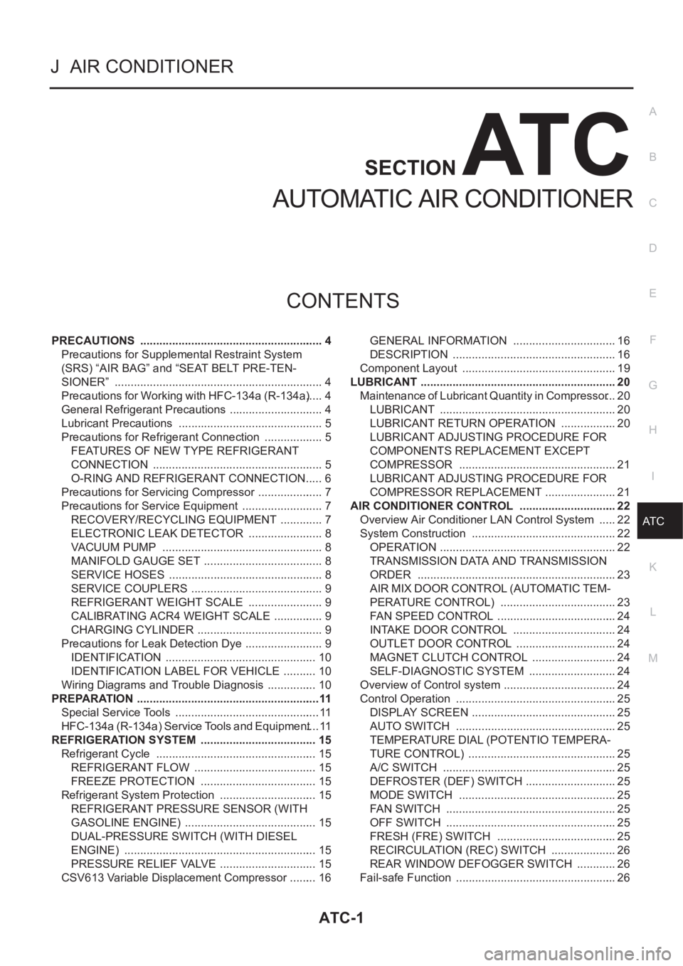
PRECAUTIONS .......................................................... 4
Precautions for Supplemental Restraint System
(SRS) “AIR BAG” and “SEAT BELT PRE-TEN-
SIONER” .................................................................. 4
Precautions for Working with HFC-134a (R-134a) ..... 4
General Refrigerant Precautions .............................. 4
Lubricant Precautions .............................................. 5
Precautions for Refrigerant Connection ................... 5
FEATURES OF NEW TYPE REFRIGERANT
CONNECTION ...................................................... 5
O-RING AND REFRIGERANT CONNECTION ..... 6
Precautions for Servicing Compressor ..................... 7
Precautions for Service Equipment .......................... 7
RECOVERY/RECYCLING EQUIPMENT .............. 7
ELECTRONIC LEAK DETECTOR ........................ 8
VACUUM PUMP ................................................... 8
MANIFOLD GAUGE SET ...................................... 8
SERVICE HOSES ................................................. 8
SERVICE COUPLERS .......................................... 9
REFRIGERANT WEIGHT SCALE ........................ 9
CALIBRATING ACR4 WEIGHT SCALE ................ 9
CHARGING CYLINDER ........................................ 9
Precautions for Leak Detection Dye ......................... 9
IDENTIFICATION ................................................ 10
IDENTIFICATION LABEL FOR VEHICLE ........... 10
Wiring Diagrams and Trouble Diagnosis ................ 10
PREPARATION ..........................................................11
Special Service Tools .............................................. 11
HFC-134a (R-134a) Service Tools and Equipment .... 11
REFRIGERATION SYSTEM ..................................... 15
Refrigerant Cycle ................................................... 15
REFRIGERANT FLOW ....................................... 15
FREEZE PROTECTION ..................................... 15
Refrigerant System Protection ............................... 15
REFRIGERANT PRESSURE SENSOR (WITH
GASOLINE ENGINE) .......................................... 15
DUAL-PRESSURE SWITCH (WITH DIESEL
ENGINE) ............................................................. 15
PRESSURE RELIEF VALVE ............................... 15
CSV613 Variable Displacement Compressor ......... 16GENERAL INFORMATION ................................. 16
DESCRIPTION .................................................... 16
Component Layout ................................................. 19
LUBRICANT .............................................................. 20
Maintenance of Lubricant Quantity in Compressor ... 20
LUBRICANT ........................................................ 20
LUBRICANT RETURN OPERATION .................. 20
LUBRICANT ADJUSTING PROCEDURE FOR
COMPONENTS REPLACEMENT EXCEPT
COMPRESSOR .................................................. 21
LUBRICANT ADJUSTING PROCEDURE FOR
COMPRESSOR REPLACEMENT ....................... 21
AIR CONDITIONER CONTROL ............................... 22
Overview Air Conditioner LAN Control System ...... 22
System Construction .............................................. 22
OPERATION ........................................................ 22
TRANSMISSION DATA AND TRANSMISSION
ORDER ............................................................... 23
AIR MIX DOOR CONTROL (AUTOMATIC TEM-
PERATURE CONTROL) ..................................... 23
FAN SPEED CONTROL ...................................... 24
INTAKE DOOR CONTROL ................................. 24
OUTLET DOOR CONTROL ................................ 24
MAGNET CLUTCH CONTROL ........................... 24
SELF-DIAGNOSTIC SYSTEM ............................ 24
Overview of Control system .................................... 24
Control Operation ................................................... 25
DISPLAY SCREEN .............................................. 25
AUTO SWITCH ................................................... 25
TEMPERATURE DIAL (POTENTIO TEMPERA-
TURE CONTROL) ............................................... 25
A/C SWITCH ....................................................... 25
DEFROSTER (DEF) SWITCH ............................. 25
MODE SWITCH .................................................. 25
FAN SWITCH ...................................................... 25
OFF SWITCH ...................................................... 25
FRESH (FRE) SWITCH ...................................... 25
RECIRCULATION (REC) SWITCH ..................... 26
REAR WINDOW DEFOGGER SWITCH ............. 26
Fail-safe Function ................................................... 26
Page 1982 of 3189

ATC-2
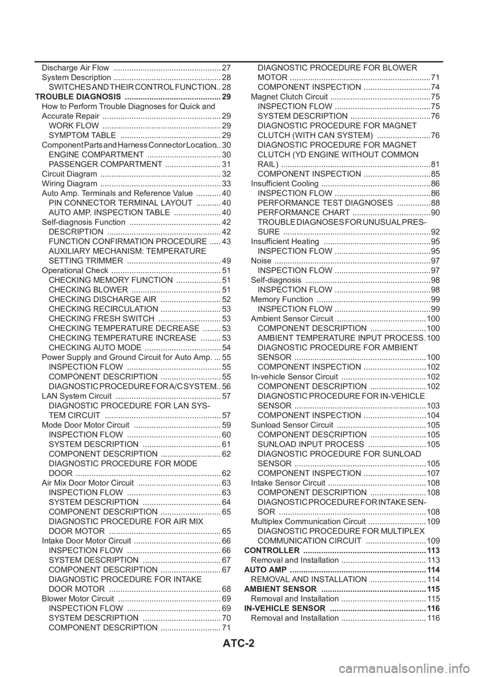
Discharge Air Flow ................................................. 27
System Description ................................................. 28
SWITCHES AND THEIR CONTROL FUNCTION ... 28
TROUBLE DIAGNOSIS ............................................ 29
How to Perform Trouble Diagnoses for Quick and
Accurate Repair ...................................................... 29
WORK FLOW ...................................................... 29
SYMPTOM TABLE .............................................. 29
Component Parts and Harness Connector Location ... 30
ENGINE COMPARTMENT .................................. 30
PASSENGER COMPARTMENT .......................... 31
Circuit Diagram ....................................................... 32
Wiring Diagram ....................................................... 33
Auto Amp. Terminals and Reference Value ............ 40
PIN CONNECTOR TERMINAL LAYOUT ............ 40
AUTO AMP. INSPECTION TABLE ...................... 40
Self-diagnosis Function .......................................... 42
DESCRIPTION .................................................... 42
FUNCTION CONFIRMATION PROCEDURE ...... 43
AUXILIARY MECHANISM: TEMPERATURE
SETTING TRIMMER ........................................... 49
Operational Check .................................................. 51
CHECKING MEMORY FUNCTION ..................... 51
CHECKING BLOWER ......................................... 51
CHECKING DISCHARGE AIR ............................ 52
CHECKING RECIRCULATION ............................ 53
CHECKING FRESH SWITCH ............................. 53
CHECKING TEMPERATURE DECREASE ......... 53
CHECKING TEMPERATURE INCREASE .......... 53
CHECKING AUTO MODE ................................... 54
Power Supply and Ground Circuit for Auto Amp. ... 55
INSPECTION FLOW ........................................... 55
COMPONENT DESCRIPTION ............................ 55
DIAGNOSTIC PROCEDURE FOR A/C SYSTEM ... 56
LAN System Circuit ............................................. ... 57
DIAGNOSTIC PROCEDURE FOR LAN SYS-
TEM CIRCUIT ..................................................... 57
Mode Door Motor Circuit ........................................ 59
INSPECTION FLOW ........................................... 60
SYSTEM DESCRIPTION .................................... 61
COMPONENT DESCRIPTION ............................ 62
DIAGNOSTIC PROCEDURE FOR MODE
DOOR .................................................................. 62
Air Mix Door Motor Circuit ...................................... 63
INSPECTION FLOW ........................................... 63
SYSTEM DESCRIPTION .................................... 64
COMPONENT DESCRIPTION ............................ 65
DIAGNOSTIC PROCEDURE FOR AIR MIX
DOOR MOTOR ................................................... 65
Intake Door Motor Circuit ........................................ 66
INSPECTION FLOW ........................................... 66
SYSTEM DESCRIPTION .................................
... 67
COMPONENT DESCRIPTION ............................ 67
DIAGNOSTIC PROCEDURE FOR INTAKE
DOOR MOTOR ................................................... 68
Blower Motor Circuit ............................................... 69
INSPECTION FLOW ........................................... 69
SYSTEM DESCRIPTION .................................... 70
COMPONENT DESCRIPTION ............................ 71DIAGNOSTIC PROCEDURE FOR BLOWER
MOTOR ................................................................ 71
COMPONENT INSPECTION ............................... 74
Magnet Clutch Circuit .............................................. 75
INSPECTION FLOW ............................................ 75
SYSTEM DESCRIPTION ..................................... 76
DIAGNOSTIC PROCEDURE FOR MAGNET
CLUTCH (WITH CAN SYSTEM) ......................... 76
DIAGNOSTIC PROCEDURE FOR MAGNET
CLUTCH (YD ENGINE WITHOUT COMMON
RAIL) .................................................................... 81
COMPONENT INSPECTION ............................... 85
Insufficient Cooling .................................................. 86
INSPECTION FLOW ............................................ 86
PERFORMANCE TEST DIAGNOSES ................ 88
PERFORMANCE CHART .................................... 90
TROUBLE DIAGNOSES FOR UNUSUAL PRES-
SURE ................................................................... 92
Insufficient Heating ................................................. 95
INSPECTION FLOW ............................................ 95
Noise ....................................................................... 97
INSPECTION FLOW ............................................ 97
Self-diagnosis ......................................................... 98
INSPECTION FLOW ............................................ 98
Memory Function .................................................... 99
INSPECTION FLOW ............................................ 99
Ambient Sensor Circuit .........................................100
COMPONENT DESCRIPTION ..........................100
AMBIENT TEMPERATURE INPUT PROCESS .100
DIAGNOSTIC PROCEDURE FOR AMBIENT
SENSOR ............................................................100
COMPONENT INSPECTION .............................102
In-vehicle Sensor Circuit .......................................102
COMPONENT DESCRIPTION ..........................102
DIAGNOSTIC PROCEDURE FOR IN-VEHICLE
SENSOR ............................................................103
COMPONENT INSPECTION .............................104
Sunload Sensor Circuit .........................................105
COMPONENT DESCRIPTION ..........................105
SUNLOAD INPUT PROCESS ...........................105
DIAGNOSTIC PROCEDURE FOR SUNLOAD
SENSOR ............................................................105
COMPONENT INSPECTION .............................107
Intake Sensor Circuit .............................................108
COMPONENT DESCRIPTION ..........................108
DIAGNOSTIC PROCEDURE FOR INTAKE SEN-
SOR ...................................................................108
Multiplex Communication Circuit ...........................109
DIAGNOSTIC PROCEDURE FOR MULTIPLEX
COMMUNICATION CIRCUIT ............................109
CONTROLLER ........................................................113
Removal and Installation .......................................113
AUTO AMP ..............................................................114
REMOVAL AND INSTALLATION ..........................114
AMBIENT SENSOR ................................................115
Removal and Installation .......................................115
IN-VEHICLE SENSOR ............................................116
Removal and Installation .......................................116
Page 1989 of 3189

PRECAUTIONS
ATC-9
C
D
E
F
G
H
I
K
L
MA
B
AT C
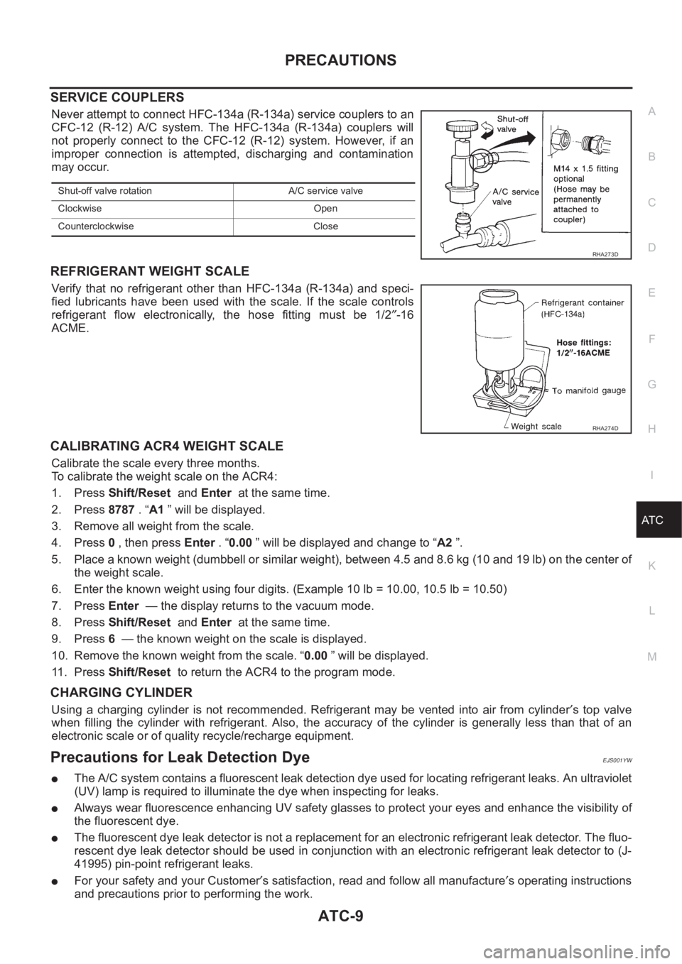
SERVICE COUPLERS
Never attempt to connect HFC-134a (R-134a) service couplers to an
CFC-12 (R-12) A/C system. The HFC-134a (R-134a) couplers will
not properly connect to the CFC-12 (R-12) system. However, if an
improper connection is attempted, discharging and contamination
may occur.
REFRIGERANT WEIGHT SCALE
Verify that no refrigerant other than HFC-134a (R-134a) and speci-
fied lubricants have been used with the scale. If the scale controls
refrigerant flow electronically, the hose fitting must be 1/2″-16
ACME.
CALIBRATING ACR4 WEIGHT SCALE
Calibrate the scale every three months.
To calibrate the weight scale on the ACR4:
1. Press Shift/Reset and Enter at the same time.
2. Press 8787 . “A1 ” will be displayed.
3. Remove all weight from the scale.
4. Press 0 , then press Enter . “0.00 ” will be displayed and change to “A2 ”.
5. Place a known weight (dumbbell or similar weight), between 4.5 and 8.6 kg (10 and 19 lb) on the center of
the weight scale.
6. Enter the known weight using four digits. (Example 10 lb = 10.00, 10.5 lb = 10.50)
7. Press Enter — the display returns to the vacuum mode.
8. Press Shift/Reset and Enter at the same time.
9. Press 6 — the known weight on the scale is displayed.
10. Remove the known weight from the scale. “0.00 ” will be displayed.
11 . P r e s s Shift/Reset to return the ACR4 to the program mode.
CHARGING CYLINDER
Using a charging cylinder is not recommended. Refrigerant may be vented into air from cylinder′s top valve
when filling the cylinder with refrigerant. Also, the accuracy of the cylinder is generally less than that of an
electronic scale or of quality recycle/recharge equipment.
Precautions for Leak Detection DyeEJS001YW
●The A/C system contains a fluorescent leak detection dye used for locating refrigerant leaks. An ultraviolet
(UV) lamp is required to illuminate the dye when inspecting for leaks.
●Always wear fluorescence enhancing UV safety glasses to protect your eyes and enhance the visibility of
the fluorescent dye.
●The fluorescent dye leak detector is not a replacement for an electronic refrigerant leak detector. The fluo-
rescent dye leak detector should be used in conjunction with an electronic refrigerant leak detector to (J-
41995) pin-point refrigerant leaks.
●For your safety and your Customer′s satisfaction, read and follow all manufacture′s operating instructions
and precautions prior to performing the work.
Shut-off valve rotation A/C service valve
Clockwise Open
Counterclockwise Close
RHA273D
RHA274D