Page 1995 of 3189
REFRIGERATION SYSTEM
ATC-15
C
D
E
F
G
H
I
K
L
MA
B
AT C
REFRIGERATION SYSTEMPFP:KA990
Refrigerant CycleEJS001Z0
REFRIGERANT FLOW
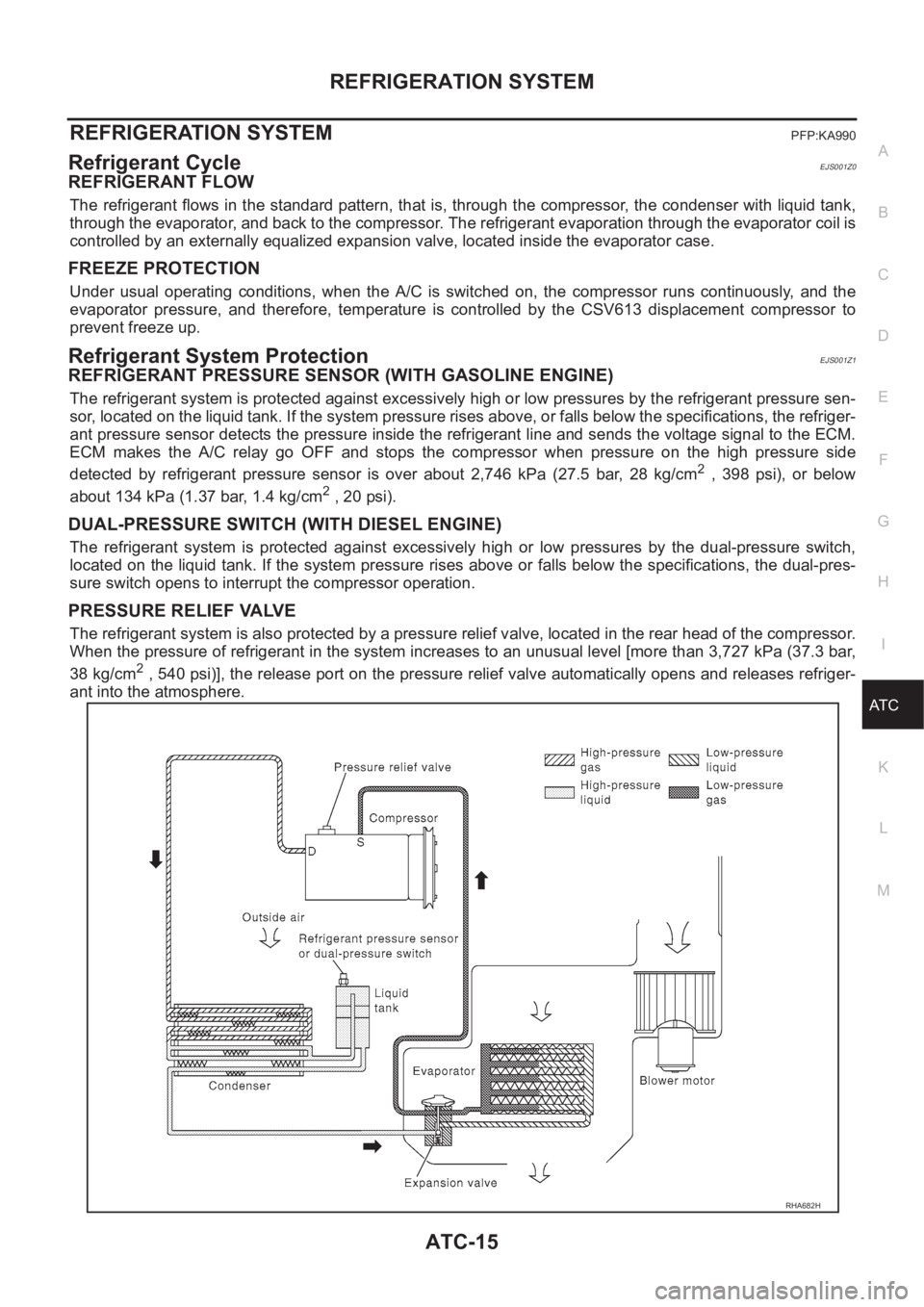
The refrigerant flows in the standard pattern, that is, through the compressor, the condenser with liquid tank,
through the evaporator, and back to the compressor. The refrigerant evaporation through the evaporator coil is
controlled by an externally equalized expansion valve, located inside the evaporator case.
FREEZE PROTECTION
Under usual operating conditions, when the A/C is switched on, the compressor runs continuously, and the
evaporator pressure, and therefore, temperature is controlled by the CSV613 displacement compressor to
prevent freeze up.
Refrigerant System ProtectionEJS001Z1
REFRIGERANT PRESSURE SENSOR (WITH GASOLINE ENGINE)
The refrigerant system is protected against excessively high or low pressures by the refrigerant pressure sen-
sor, located on the liquid tank. If the system pressure rises above, or falls below the specifications, the refriger-
ant pressure sensor detects the pressure inside the refrigerant line and sends the voltage signal to the ECM.
ECM makes the A/C relay go OFF and stops the compressor when pressure on the high pressure side
detected by refrigerant pressure sensor is over about 2,746 kPa (27.5 bar, 28 kg/cm
2 , 398 psi), or below
about 134 kPa (1.37 bar, 1.4 kg/cm
2 , 20 psi).
DUAL-PRESSURE SWITCH (WITH DIESEL ENGINE)
The refrigerant system is protected against excessively high or low pressures by the dual-pressure switch,
located on the liquid tank. If the system pressure rises above or falls below the specifications, the dual-pres-
sure switch opens to interrupt the compressor operation.
PRESSURE RELIEF VALVE
The refrigerant system is also protected by a pressure relief valve, located in the rear head of the compressor.
When the pressure of refrigerant in the system increases to an unusual level [more than 3,727 kPa (37.3 bar,
38 kg/cm
2 , 540 psi)], the release port on the pressure relief valve automatically opens and releases refriger-
ant into the atmosphere.
RHA682H
Page 2004 of 3189
ATC-24
AIR CONDITIONER CONTROL
FAN SPEED CONTROL
Blower speed is automatically controlled based on temperature setting, ambient temperature, in-vehicle tem-
perature, intake temperature, amount of sunload and air mix door position.
With FAN switch set to AUTO, the blower motor starts to gradually increase air flow volume.
When engine coolant temperature is low, the blower motor operation is delayed to prevent cool air from flow-
ing.
INTAKE DOOR CONTROL
The intake doors are automatically controlled by: The temperature setting, ambient temperature, in-vehicle
temperature, intake temperature, amount of sunload and ON-OFF operation of the compressor.
OUTLET DOOR CONTROL
The outlet door is automatically controlled by: The temperature setting, ambient temperature, in-vehicle tem-
perature, intake temperature and amount of sunload.
MAGNET CLUTCH CONTROL
The ECM controls compressor operation using input signals from the refrigerant pressure sensor (with QG
engine), throttle position sensor and auto amplifier.
SELF-DIAGNOSTIC SYSTEM
The self-diagnostic system is built into the auto amplifier (LCU) to quickly locate the cause of problems.
Overview of Control systemEJS001Z7
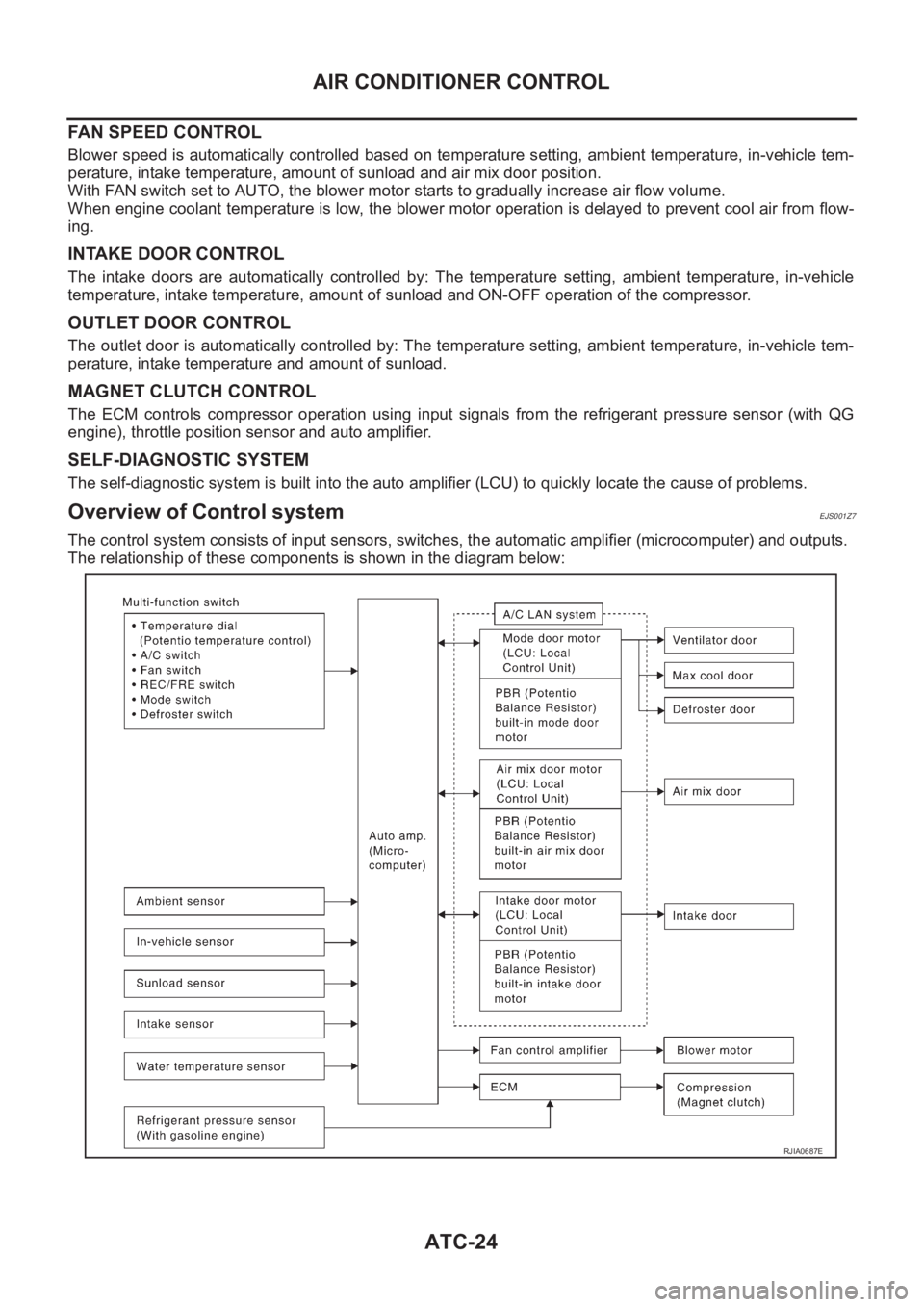
The control system consists of input sensors, switches, the automatic amplifier (microcomputer) and outputs.
The relationship of these components is shown in the diagram below:
RJIA0687E
Page 2007 of 3189
AIR CONDITIONER CONTROL
ATC-27
C
D
E
F
G
H
I
K
L
MA
B
AT C
Discharge Air FlowEJS001ZA
RJIA1676E
Page 2009 of 3189
TROUBLE DIAGNOSIS
ATC-29
C
D
E
F
G
H
I
K
L
MA
B
AT C
TROUBLE DIAGNOSISPFP:00004
How to Perform Trouble Diagnoses for Quick and Accurate RepairEJS001ZC
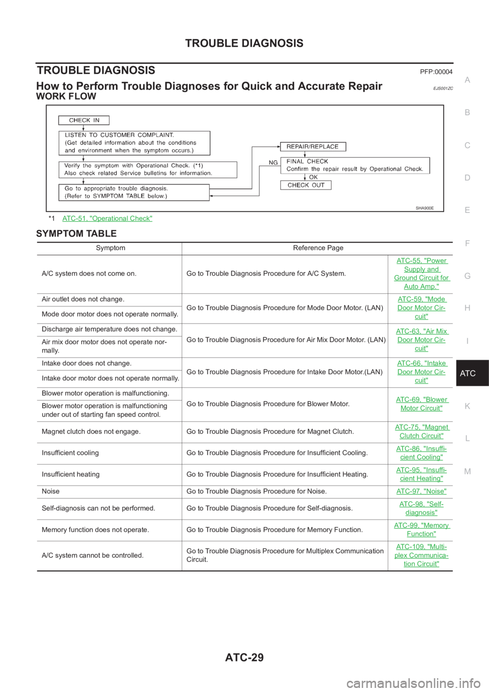
WORK FLOW
SYMPTOM TABLE
*1AT C - 5 1 , "Operational Check"
SHA900E
Symptom Reference Page
A/C system does not come on. Go to Trouble Diagnosis Procedure for A/C System.ATC-55, "
Power
Supply and
Ground Circuit for
Auto Amp."
Air outlet does not change.
Go to Trouble Diagnosis Procedure for Mode Door Motor. (LAN)AT C - 5 9 , "Mode
Door Motor Cir-
cuit"Mode door motor does not operate normally.
Discharge air temperature does not change.
Go to Trouble Diagnosis Procedure for Air Mix Door Motor. (LAN)ATC-63, "
Air Mix
Door Motor Cir-
cuit"Air mix door motor does not operate nor-
mally.
Intake door does not change.
Go to Trouble Diagnosis Procedure for Intake Door Motor.(LAN)AT C - 6 6 , "
Intake
Door Motor Cir-
cuit"Intake door motor does not operate normally.
Blower motor operation is malfunctioning.
Go to Trouble Diagnosis Procedure for Blower Motor.ATC-69, "
Blower
Motor Circuit"Blower motor operation is malfunctioning
under out of starting fan speed control.
Magnet clutch does not engage. Go to Trouble Diagnosis Procedure for Magnet Clutch.AT C - 7 5 , "
Magnet
Clutch Circuit"
Insufficient cooling Go to Trouble Diagnosis Procedure for Insufficient Cooling.AT C - 8 6 , "Insuffi-
cient Cooling"
Insufficient heating Go to Trouble Diagnosis Procedure for Insufficient Heating.AT C - 9 5 , "Insuffi-
cient Heating"
Noise Go to Trouble Diagnosis Procedure for Noise.ATC-97, "Noise"
Self-diagnosis can not be performed. Go to Trouble Diagnosis Procedure for Self-diagnosis.AT C - 9 8 , "Self-
diagnosis"
Memory function does not operate. Go to Trouble Diagnosis Procedure for Memory Function.AT C - 9 9 , "Memory
Function"
A/C system cannot be controlled.Go to Trouble Diagnosis Procedure for Multiplex Communication
Circuit.ATC-109, "
Multi-
plex Communica-
tion Circuit"
Page 2026 of 3189
ATC-46
TROUBLE DIAGNOSIS
8. CHECK ACTUATORS
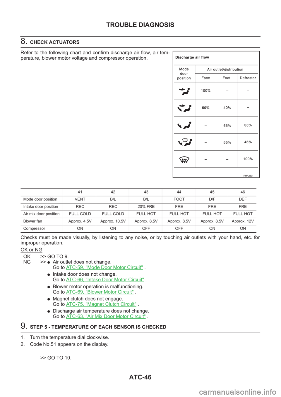
Refer to the following chart and confirm discharge air flow, air tem-
perature, blower motor voltage and compressor operation.
Checks must be made visually, by listening to any noise, or by touching air outlets with your hand, etc. for
improper operation.
OK or NG
OK >> GO TO 9.
NG >>
●Air outlet does not change.
Go to AT C - 5 9 , "
Mode Door Motor Circuit" .
●Intake door does not change.
Go to AT C - 6 6 , "
Intake Door Motor Circuit" .
●Blower motor operation is malfunctioning.
Go to AT C - 6 9 , "
Blower Motor Circuit" .
●Magnet clutch does not engage.
Go to AT C - 7 5 , "
Magnet Clutch Circuit" .
●Discharge air temperature does not change.
Go to AT C - 6 3 , "
Air Mix Door Motor Circuit" .
9. STEP 5 - TEMPERATURE OF EACH SENSOR IS CHECKED
1. Turn the temperature dial clockwise.
2. Code No.51 appears on the display.
>> GO TO 10.
RHA280I
41 42 43 44 45 46
Mode door position VENT B/L B/L FOOT D/F DEF
Intake door position REC REC 20% FRE FRE FRE FRE
Air mix door position FULL COLD FULL COLD FULL HOT FULL HOT FULL HOTFULL HOT
Blower fan Approx. 4.5V Approx. 10.5V Approx. 8.5V Approx. 8.5V Approx. 8.5V Approx. 12V
Compressor ON ON OFF OFF ON ON
Page 2032 of 3189
ATC-52
TROUBLE DIAGNOSIS
CHECKING DISCHARGE AIR
1. Press mode switch four times and DEF button.
2. Each position indicator should change shape.
3. Confirm that discharge air comes out according to the air distri-
bution table. Refer to ATC-27, "
Discharge Air Flow" .
Intake door position is checked in the next step.
If NG, go to AT C - 5 9 , "
Mode Door Motor Circuit" .
If OK, continue with next check.
NOTE:
Confirm that the compressor clutch is engaged (visual inspection)
and intake door position is at FRESH when the DEF is selected.
RJIA1685E
RHA280I
Page 2035 of 3189
TROUBLE DIAGNOSIS
ATC-55
C
D
E
F
G
H
I
K
L
MA
B
AT C
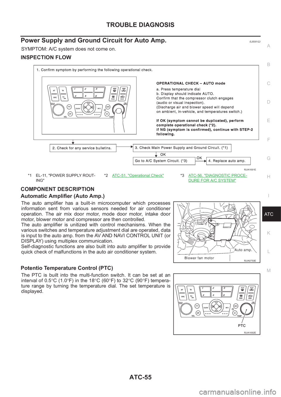
Power Supply and Ground Circuit for Auto Amp.EJS001ZJ
SYMPTOM: A/C system does not come on.
INSPECTION FLOW
COMPONENT DESCRIPTION
Automatic Amplifier (Auto Amp.)
The auto amplifier has a built-in microcomputer which processes
information sent from various sensors needed for air conditioner
operation. The air mix door motor, mode door motor, intake door
motor, blower motor and compressor are then controlled.
The auto amplifier is unitized with control mechanisms. When the
various switches and temperature adjustment dial are operated, data
is input to the auto amp. from the AV AND NAVI CONTROL UNIT (or
DISPLAY) using multiplex communication.
Self-diagnostic functions are also built into auto amplifier to provide
quick check of malfunctions in the auto air conditioner system.
Potentio Temperature Control (PTC)
The PTC is built into the multi-function switch. It can be set at an
interval of 0.5°C (1.0°F) in the 18°C (60°F) to 32°C (90°F) tempera-
ture range by turning the temperature dial. The set temperature is
displayed.
*1 EL-11, "POWER SUPPLY ROUT-
ING"*2AT C - 5 1 , "Operational Check"*3AT C - 5 6 , "DIAGNOSTIC PROCE-
DURE FOR A/C SYSTEM"
RJIA1691E
RJIA0750E
RJIA1692E
Page 2040 of 3189
ATC-60
TROUBLE DIAGNOSIS
INSPECTION FLOW
*1AT C - 2 7 , "Discharge Air Flow"*2ATC-51, "Operational Check"*3AT C - 4 2 , "Self-diagnosis Function",
see No.1
*4AT C - 4 2 , "
Self-diagnosis Function",
see No. 5*5ATC-100, "Ambient Sensor Circuit"*6ATC-102, "In-vehicle Sensor Circuit"
*7ATC-105, "Sunload Sensor Circuit"*8ATC-63, "Air Mix Door Motor Circuit"*9AT C - 4 2 , "Self-diagnosis Function",
see No.14
*10AT C - 5 7 , "
LAN System Circuit"*11ATC-62, "COMPONENT DESCRIP-
TION"
*12AT C - 5 1 , "Operational Check"
*13AT C - 2 9 , "SYMPTOM TABLE"*14ATC-108, "Intake Sensor Circuit"*15AT C - 5 2 , "CHECKING DISCHARGE
AIR"
RJIA1693E