2003 NISSAN ALMERA N16 flow
[x] Cancel search: flowPage 1343 of 3189
NJMT0008
SMT928D
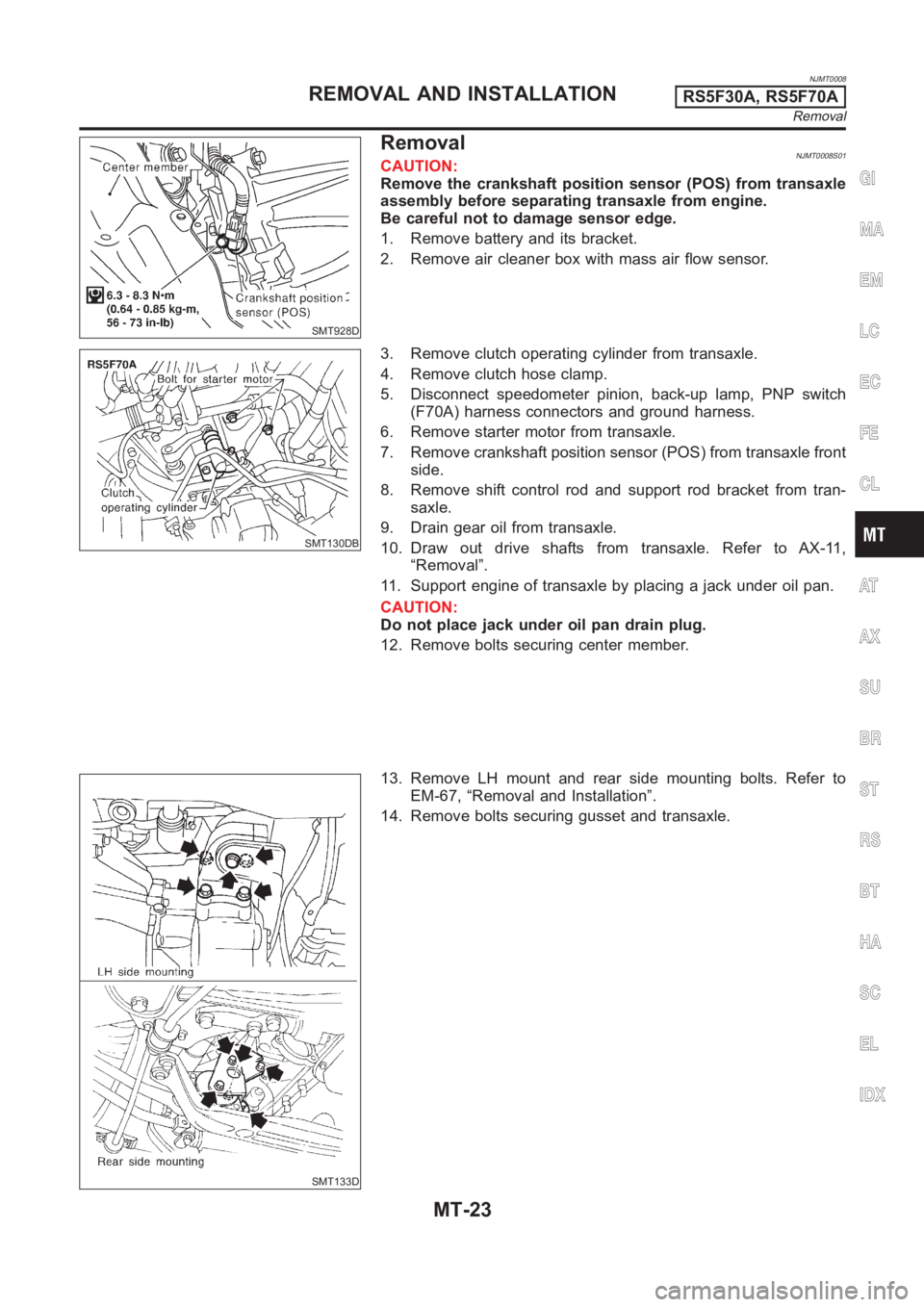
RemovalNJMT0008S01CAUTION:
Remove the crankshaft position sensor (POS) from transaxle
assembly before separating transaxle from engine.
Be careful not to damage sensor edge.
1. Remove battery and its bracket.
2. Remove air cleaner box with mass air flow sensor.
SMT130DB
3. Remove clutch operating cylinder from transaxle.
4. Remove clutch hose clamp.
5. Disconnect speedometer pinion, back-up lamp, PNP switch
(F70A) harness connectors and ground harness.
6. Remove starter motor from transaxle.
7. Remove crankshaft position sensor (POS) from transaxle front
side.
8. Remove shift control rod and support rod bracket from tran-
saxle.
9. Drain gear oil from transaxle.
10. Draw out drive shafts from transaxle. Refer to AX-11,
“Removal”.
11. Support engine of transaxle by placing a jack under oil pan.
CAUTION:
Do not place jack under oil pan drain plug.
12. Remove bolts securing center member.
SMT133D
13. Remove LH mount and rear side mounting bolts. Refer to
EM-67, “Removal and Installation”.
14. Remove bolts securing gusset and transaxle.
GI
MA
EM
LC
EC
FE
CL
AT
AX
SU
BR
ST
RS
BT
HA
SC
EL
IDX
REMOVAL AND INSTALLATIONRS5F30A, RS5F70A
Removal
MT-23
Page 1346 of 3189
NJMT0090
SMT928D
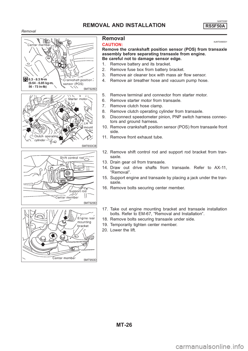
RemovalNJMT0090S01CAUTION:
Remove the crankshaft position sensor (POS) from transaxle
assembly before separating transaxle from engine.
Be careful not to damage sensor edge.
1. Remove battery and its bracket.
2. Remove fuse box from battery bracket.
3. Remove air cleaner box with mass air flow sensor.
4. Remove air breather hose and vacuum pump hose.
SMT650CB
5. Remove terminal and connector from starter motor.
6. Remove starter motor from transaxle.
7. Remove clutch hose clamp.
8. Remove clutch operating cylinder from transaxle.
9. Disconnect speedometer pinion, PNP switch harness connec-
tors and ground harness.
10. Remove crankshaft position sensor (POS) from transaxle front
side.
11. Remove front exhaust tube.
SMT929D
12. Remove shift control rod and support rod bracket from tran-
saxle.
13. Drain gear oil from transaxle.
14. Draw out drive shafts from transaxle. Refer to AX-11,
“Removal”.
15. Support engine and transaxle by placing a jack under the tran-
saxle.
16. Remove bolts securing center member.
SMT950D
17. Take out engine mounting bracket and transaxle installation
bolts. Refer to EM-67, “Removal and Installation”.
18. Remove bolts securing transaxle under side.
19. Temporarily tighten center member.
20. Lower the lift.
REMOVAL AND INSTALLATIONRS5F50A
Removal
MT-26
Page 1457 of 3189
AT-1
AUTOMATIC TRANSAXLE
C TRANSMISSION/TRANSAXLE
CONTENTS
D
E
F
G
H
I
J
K
L
M
SECTION
A
B
AT
AUTOMATIC TRANSAXLE
PRECAUTIONS .......................................................... 5
Precautions for Supplemental Restraint System
(SRS) “AIR BAG” and “SEAT BELT PRE-TEN-
SIONER” .................................................................. 5
Precautions for On Board Diagnostic (EURO-OBD)
System of A/T and Engine — Euro-OBD — ............. 5
Precautions for Trouble Diagnosis ........................... 5
Precautions for Harness Repair ............................... 5
Precautions .............................................................. 6
Service Notice or Precautions .................................. 7
Wiring Diagrams and Trouble Diagnosis .................. 8
PREPARATION ........................................................... 9
Special Service Tools ............................................... 9
Commercial Service Tools ...................................... 12
A/T FLUID ................................................................. 13
Checking A/T Fluid ................................................. 13
Changing A/T Fluid ............................................. ... 13
OVERALL SYSTEM ................................................. 14
A/T Electrical Parts Location .................................. 14
Circuit Diagram ...................................................... 15
Cross-Sectional View ............................................. 16
Hydraulic Control Circuit ........................................ 17
Shift Mechanism ..................................................... 18
Control System ....................................................... 27
Control Mechanism ................................................ 28
Control Valve .......................................................... 34
EURO-OBD
TROUBLE DIAGNOSIS — INDEX ........................... 35
Alphabetical & P No. Index for DTC ....................... 35
ON BOARD DIAGNOSTIC SYSTEM DESCRIP-
TION .......................................................................... 37
Introduction ............................................................ 37
EURO-OBD Function for A/T System .................... 37
One or Two Trip Detection Logic of EURO-OBD ... 37
EURO-OBD Diagnostic Trouble Code (DTC) ......... 37
Malfunction Indicator (MI) ....................................... 41
CONSULT-II ........................................................... 41
Diagnostic Procedure Without CONSULT-II ........... 50TROUBLE DIAGNOSIS — INTRODUCTION ........... 56
Introduction ............................................................. 56
Work Flow ............................................................... 60
TROUBLE DIAGNOSIS — BASIC INSPECTION .... 63
A/T Fluid Check ...................................................... 63
Stall Test ................................................................. 64
Line Pressure Test .................................................. 67
Road Test ............................................................... 68
TROUBLE DIAGNOSIS — GENERAL DESCRIP-
TION .......................................................................... 86
Symptom Chart ....................................................... 86
TCM Terminals and Reference Value ...................106
CAN COMMUNICATION .........................................109
System Description ...............................................109
CAN Communication Unit .....................................109
DTC P0705 PARK/NEUTRAL POSITION (PNP)
SWITCH ...................................................................111
Description .............................................................111
Wiring Diagram — AT — PNP/SW .......................113
Diagnostic Procedure ...........................................114
Component Inspection ..........................................116
DTC P0710 A/T FLUID TEMPERATURE SENSOR
CIRCUIT ..................................................................117
Description ............................................................117
Wiring Diagram — AT — FTS ..............................119
Diagnostic Procedure ...........................................120
Component Inspection ..........................................122
DTC P0720 VEHICLE SPEED SENSOR A/T (REV-
OLUTION SENSOR) ...............................................123
Description ............................................................123
Wiring Diagram — AT — VSSA/T ........................126
Diagnostic Procedure ...........................................127
DTC P0725 ENGINE SPEED SIGNAL ...................129
Description ............................................................129
Wiring Diagram — AT — ENGSS .........................130
Diagnostic Procedure ..........................................
.131
DTC P0731 A/T 1ST GEAR FUNCTION ................133
Description ............................................................133
Wiring Diagram — AT — 1ST ...............................136
Page 1458 of 3189
AT-2
Diagnostic Procedure ...........................................137
Component Inspection ..........................................138
DTC P0732 A/T 2ND GEAR FUNCTION ................139
Description ............................................................139
Wiring Diagram — AT — 2ND ..............................142
Diagnostic Procedure ...........................................143
Component Inspection ..........................................144
DTC P0733 A/T 3RD GEAR FUNCTION ................145
Description ............................................................145
Wiring Diagram — AT — 3RD ..............................148
Diagnostic Procedure ...........................................149
Component Inspection ..........................................150
DTC P0734 A/T 4TH GEAR FUNCTION ................151
Description ............................................................151
Wiring Diagram — AT — 4TH ...............................154
Diagnostic Procedure ...........................................155
Component Inspection ..........................................158
DTC P0740 TORQUE CONVERTER CLUTCH
SOLENOID VALVE .................................................159
Description ............................................................159
Wiring Diagram — AT — TCV ..............................161
Diagnostic Procedure ...........................................162
Component Inspection ..........................................163
DTC P0745 LINE PRESSURE SOLENOID VALVE .164
Description ............................................................164
Wiring Diagram — AT — LPSV ............................166
Diagnostic Procedure ...........................................167
Component Inspection ..........................................169
DTC P0750 SHIFT SOLENOID VALVE A ...............171
Description ............................................................171
Wiring Diagram — AT — SSV/A ...........................173
Diagnostic Procedure ...........................................174
Component Inspection ..........................................175
DTC P0755 SHIFT SOLENOID VALVE B ...............176
Description ............................................................176
Wiring Diagram — AT — SSV/B ...........................178
Diagnostic Procedure ...........................................179
Component Inspection ..........................................179
DTC P1705 ACCELERATOR PEDAL POSITION
(APP) SENSOR .......................................................181
Description ............................................................181
Wiring Diagram — AT — TPS ..............................184
Diagnostic Procedure ...........................................185
DTC P1760 OVERRUN CLUTCH SOLENOID
VALVE .....................................................................187
Description ............................................................187
Wiring Diagram — AT — OVRCSV ......................189
Diagnostic Procedure ...........................................190
Component Inspection ..........................................191
DTC U1000 CAN COMMUNICATION LINE ............192
Description ............................................................192
On Board Diagnosis Logic ....................................192
DTC Confirmation Procedure ...............................192
Wiring Diagram — AT ...........................................193
Diagnostic Procedure ...........................................194
DTC BATT/FLUID TEMP SEN (A/T FLUID TEMP
SENSOR CIRCUIT AND TCM POWER SOURCE) .195
Description ............................................................195
Wiring Diagram — AT — BA/FTS .........................197Diagnostic Procedure ............................................198
Component Inspection ..........................................200
DTC VEHICLE SPEED SENSOR MTR ...................201
Description ............................................................201
Wiring Diagram — AT — VSSMTR .......................203
Diagnostic Procedure ............................................204
DTC CONTROL UNIT (RAM), CONTROL UNIT
(ROM) ......................................................................205
Description ............................................................205
Diagnostic Procedure ............................................206
DTC CONTROL UNIT (EEP ROM) .........................207
Description ............................................................207
Diagnostic Procedure ............................................208
TROUBLE DIAGNOSES FOR SYMPTOMS ...........209
Wiring Diagram — AT — NONDTC ......................209
1. O/D OFF Indicator Lamp Does Not Come On ..211
2. Engine Cannot Be Started In “P” and “N” Position .212
3. In “P” Position, Vehicle Moves Forward Or Back-
ward When Pushed ...............................................213
4. In “N” Position, Vehicle Moves ..........................214
5. Large Shock. “N” → “R” Position ......................215
6. Vehicle Does Not Creep Backward In “R” Position .216
7. Vehicle Does Not Creep Forward In “D”, “2” Or
“1” Position ............................................................219
8. Vehicle Cannot Be Started From D
1 .................221
9. A/T Does Not Shift: D
1→ D2 Or Does Not Kick-
down: D
4→ D2 .....................................................223
10. A/T Does Not Shift: D
2→ D3 ..........................225
11. A/T Does Not Shift: D
3→ D4 ...........................227
12. A/T Does Not Perform Lock-up .......................230
13. A/T Does Not Hold Lock-up Condition ............231
14. Lock-up Is Not Released .................................232
15. Engine Speed Does Not Return To Idle (Light
Braking D
4→ D3 ) .................................................233
16. Vehicle Does Not Start From D
1 .....................234
17. A/T Does Not Shift: D
4→ D3 , W h e n O v e r d r i v e
Control Switch “ON” → “OFF” ...............................235
18. A/T Does Not Shift: D
3→ 22 , When Selector
Lever “D” → “2” Position .......................................235
19. A/T Does Not Shift: 2
2→ 11 , When Selector
Lever “2” → “1” Position ........................................236
20. Vehicle Does Not Decelerate By Engine Brake .237
21. TCM Self-diagnosis Does Not Activate (PNP &
Overdrive Control Switches, and Throttle Position
Sensor Circuit Checks) .........................................237
EXC.F/EURO-OBD
ON BOARD DIAGNOSTIC SYSTEM DESCRIP-
TION ........................................................................244
CONSULT-II ..........................................................244
Diagnostic Procedure Without CONSULT-II .........250
TROUBLE DIAGNOSIS — INTRODUCTION .........255
Introduction ...........................................................255
Work Flow .............................................................259
TROUBLE DIAGNOSIS — BASIC INSPECTION ...261
A/T Fluid Check ....................................................261
Stall Test ................................................................262
Page 1463 of 3189
PRECAUTIONS
AT-7
D
E
F
G
H
I
J
K
L
MA
B
AT
●After performing each TROUBLE DIAGNOSIS, perform
“DTC (Diagnostic Trouble Code) CONFIRMATION PROCE-
DURE”.
The DTC should not be displayed in the “DTC CONFIRMA-
TION PROCEDURE” if the repair is completed.
●Before proceeding with disassembly, thoroughly clean the out-
side of the transaxle. It is important to prevent the internal parts
from becoming contaminated by dirt or other foreign matter.
●Disassembly should be done in a clean work area.
●Use lint-free cloth or towels for wiping parts clean. Common
shop rags can leave fibers that could interfere with the operation
of the transaxle.
●Place disassembled parts in order for easier and proper assembly.
●All parts should be carefully cleaned with a general purpose, non-flammable solvent before inspection or
reassembly.
●Gaskets, seals and O-rings should be replaced any time the transaxle is disassembled.
●It is very important to perform functional tests whenever they are indicated.
●The valve body contains precision parts and requires extreme care when parts are removed and serviced.
Place disassembled valve body parts in order for easier and proper assembly. Care will also prevent
springs and small parts from becoming scattered or lost.
●Properly installed valves, sleeves, plugs, etc. will slide along bores in valve body under their own weight.
●Before assembly, apply a coat of recommended ATF to all parts. Apply petroleum jelly to protect O-rings
and seals, or hold bearings and washers in place during assembly. Do not use grease.
●Extreme care should be taken to avoid damage to O-rings, seals and gaskets when assembling.
●After overhaul, refill the transaxle with new ATF.
●When the A/T drain plug is removed, only some of the fluid is drained. Old A/T fluid will remain in torque
converter and ATF cooling system.
Always follow the procedures under AT-13, "
Changing A/T Fluid" when changing A/T fluid.
Service Notice or PrecautionsECS007N8
FA I L - S A F E
The TCM has an electronic Fail-Safe (limp home mode). This allows the vehicle to be driven even if a major
electrical input/output device circuit is damaged.
Under Fail-Safe, the vehicle always runs in third gear, even with a shift lever position of “1”, “2” or “D”. The cus-
tomer may complain of sluggish or poor acceleration.
When the ignition key is turned “ON” following Fail-Safe operation, O/D OFF indicator lamp blinks for about 8
seconds. Refer to AT- 2 5 0 , "
Diagnostic Procedure Without CONSULT-II" (EXCEPT FOR EURO-OBD) or AT-
51, "TCM SELF-DIAGNOSTIC PROCEDURE (NO TOOLS)" (EURO-OBD).
The blinking of the O/D OFF indicator lamp for about 8 seconds will appear only once and be cleared. The
customer may resume normal driving conditions.
Always follow the “Work Flow”, refer to AT- 2 5 9
(EXCEPT FOR EURO-OBD) or AT- 6 0 (EURO-OBD).
The SELF-DIAGNOSIS results will be as follows:
●The first SELF-DIAGNOSIS will indicate damage to the vehicle speed sensor or the revolution sensor.
●During the next SELF-DIAGNOSIS, performed after checking the sensor, no damages will be indicated.
TORQUE CONVERTER SERVICE
The torque converter should be replaced under any of the following conditions:
●External leaks in the hub weld area.
●Converter hub is scored or damaged.
●Converter pilot is broken, damaged or fits poorly into crankshaft.
●Steel particles are found after flushing the cooler and cooler lines.
●Pump is damaged or steel particles are found in the converter.
●Vehicle has TCC shudder and/or no TCC apply. Replace only after all hydraulic and electrical diagnoses
have been made. (Converter clutch material may be glazed.)
●Converter is contaminated with engine coolant containing antifreeze.
SAT652J
Page 1512 of 3189
![NISSAN ALMERA N16 2003 Electronic Repair Manual AT-56
[EURO-OBD]
TROUBLE DIAGNOSIS — INTRODUCTION
TROUBLE DIAGNOSIS — INTRODUCTION
PFP:00000
IntroductionECS007NU
The TCM receives a signal from the vehicle speed sensor, throttle
position sensor NISSAN ALMERA N16 2003 Electronic Repair Manual AT-56
[EURO-OBD]
TROUBLE DIAGNOSIS — INTRODUCTION
TROUBLE DIAGNOSIS — INTRODUCTION
PFP:00000
IntroductionECS007NU
The TCM receives a signal from the vehicle speed sensor, throttle
position sensor](/manual-img/5/57350/w960_57350-1511.png)
AT-56
[EURO-OBD]
TROUBLE DIAGNOSIS — INTRODUCTION
TROUBLE DIAGNOSIS — INTRODUCTION
PFP:00000
IntroductionECS007NU
The TCM receives a signal from the vehicle speed sensor, throttle
position sensor or PNP switch and provides shift control or lock-up
control via A/T solenoid valves.
The TCM also communicates with the ECM by means of a signal
sent from sensing elements used with the EURO-OBD related parts
of the A/T system for malfunction-diagnostic purposes. The TCM is
capable of diagnosing malfunctioning parts while the ECM can store
malfunctions in its memory.
Input and output signals must always be correct and stable in the
operation of the A/T system. The A/T system must be in good oper-
ating condition and be free of valve seizure, solenoid valve malfunc-
tion, etc.
It is much more difficult to diagnose a problem that occurs intermit-
tently rather than continuously. Most intermittent problems are
caused by poor electric connections or improper wiring. In this case,
careful checking of suspected circuits may help prevent the replace-
ment of good parts.
A visual check only, may not find the cause of the problems. A road
test with CONSULT-II (or GST) or a circuit tester connected should
be performed. Follow the “Work Flow”. Refer to AT- 6 0 , "
Work Flow" .
Before undertaking actual checks, take a few minutes to talk with a
customer who approaches with a drive ability complaint. The cus-
tomer can supply good information about such problems, especially
intermittent ones. Find out what symptoms are present and under
what conditions they occur. A “Diagnostic Worksheet” like the exam-
ple (AT- 5 7 , "
DIAGNOSTIC WORKSHEET" ) should be used.
Start your diagnosis by looking for “conventional” problems first. This
will help troubleshoot drive ability problems on an electronically con-
trolled engine vehicle.
Also check related Service bulletins for information.
SAT631IA
SAT632I
SEF234G
Page 1516 of 3189
![NISSAN ALMERA N16 2003 Electronic Repair Manual AT-60
[EURO-OBD]
TROUBLE DIAGNOSIS — INTRODUCTION
Work Flow
ECS007NV
HOW TO PERFORM TROUBLE DIAGNOSES FOR QUICK AND ACCURATE REPAIR
A good understanding of the malfunction conditions can mak NISSAN ALMERA N16 2003 Electronic Repair Manual AT-60
[EURO-OBD]
TROUBLE DIAGNOSIS — INTRODUCTION
Work Flow
ECS007NV
HOW TO PERFORM TROUBLE DIAGNOSES FOR QUICK AND ACCURATE REPAIR
A good understanding of the malfunction conditions can mak](/manual-img/5/57350/w960_57350-1515.png)
AT-60
[EURO-OBD]
TROUBLE DIAGNOSIS — INTRODUCTION
Work Flow
ECS007NV
HOW TO PERFORM TROUBLE DIAGNOSES FOR QUICK AND ACCURATE REPAIR
A good understanding of the malfunction conditions can make troubleshooting faster and more accurate. In
general, each customer feels differently about a problem. It is important to fully understand the symptoms or
conditions for a customer complaint.
Make good use of the two sheets provided, “Information From Customer” (AT- 5 7
) and “Diagnostic Worksheet”
(AT- 5 8
), to perform the best troubleshooting possible.
8.❏ Perform the Diagnostic Procedures for all remaining items marked NG. Repair or replace the damaged parts.
Refer to the Symptom Chart when you perform the procedures. (The chart also shows some other possible
symptoms and the component inspection orders.)AT- 7 , "Ser-
vice Notice or
Precautions"
9.❏ Erase DTC from TCM and ECM memories.AT-39, "HOW
TO ERASE
DTC"
Page 1517 of 3189
![NISSAN ALMERA N16 2003 Electronic Repair Manual TROUBLE DIAGNOSIS — INTRODUCTION
AT-61
[EURO-OBD]
D
E
F
G
H
I
J
K
L
MA
B
AT
WORK FLOW CHART
SAT183K NISSAN ALMERA N16 2003 Electronic Repair Manual TROUBLE DIAGNOSIS — INTRODUCTION
AT-61
[EURO-OBD]
D
E
F
G
H
I
J
K
L
MA
B
AT
WORK FLOW CHART
SAT183K](/manual-img/5/57350/w960_57350-1516.png)
TROUBLE DIAGNOSIS — INTRODUCTION
AT-61
[EURO-OBD]
D
E
F
G
H
I
J
K
L
MA
B
AT
WORK FLOW CHART
SAT183K