2003 NISSAN ALMERA N16 Electric
[x] Cancel search: ElectricPage 1052 of 3189
![NISSAN ALMERA N16 2003 Electronic Repair Manual EC-722
[QG (WITHOUT EURO-OBD)]
SERVICE DATA AND SPECIFICATIONS (SDS)
SERVICE DATA AND SPECIFICATIONS (SDS)
PFP:00030
Fuel PressureEBS00KML
Idle Speed and Ignition TimingEBS00KMM
*1: Under the followin NISSAN ALMERA N16 2003 Electronic Repair Manual EC-722
[QG (WITHOUT EURO-OBD)]
SERVICE DATA AND SPECIFICATIONS (SDS)
SERVICE DATA AND SPECIFICATIONS (SDS)
PFP:00030
Fuel PressureEBS00KML
Idle Speed and Ignition TimingEBS00KMM
*1: Under the followin](/manual-img/5/57350/w960_57350-1051.png)
EC-722
[QG (WITHOUT EURO-OBD)]
SERVICE DATA AND SPECIFICATIONS (SDS)
SERVICE DATA AND SPECIFICATIONS (SDS)
PFP:00030
Fuel PressureEBS00KML
Idle Speed and Ignition TimingEBS00KMM
*1: Under the following conditions:
●Air conditioner switch: OFF
●Electric load: OFF (Lights, heater fan & rear window defogger)
●Steering wheel: Kept in straight-ahead position
Calculated Load ValueEBS00KMN
Mass Air Flow SensorEBS00KMO
*: Engine is warmed up to normal operating temperature and running under no-load.
Intake Air Temperature SensorEBS00KMP
Engine Coolant Temperature SensorEBS00KMQ
Heated Oxygen Sensor 1 HeaterEBS00KMR
Heated Oxygen sensor 2 HeaterEBS00KMS
Crankshaft Position Sensor (POS)EBS00KMT
Refer to EC-559, "Component Inspection" .
Camshaft Position Sensor (PHASE)EBS00KMU
Refer to EC-566, "Component Inspection" .
Fuel pressure at idle
Approximately 350 kPa (3.5bar, 3.57kg/cm2 , 51psi)
Target idle speed
No-load*1 (in “P” or N” position)A/T: 800±50 rpm
M/T: 700±50 rpm
Air conditioner: ON In “P” or N” position 900 rpm or more
Ignition timingIn “P” or N” position A/T: 10°±5° BTDC
M/T: 8°±5° BTDC
Calculated load value % (Using CONSULT-II)
At idle10 - 35
At 2,500 rpm10 - 35
Supply voltageBattery voltage (11 - 14V)
Output voltage at idle1.0 - 1.7*V
Mass air flow (Using CONSULT-II)1.0 - 4.0 g·m/sec at idle*
5.0 - 10.0 g·m/sec at 2,500 rpm*
Temperature °C (°F) Resistance kΩ
25 (77)1.9 - 2.1
80 (176)0.31 - 0.37
Temperature °C (°F) Resistance kΩ
20 (68) 2.1 - 2.9
50 (122) 0.68 - 1.00
90 (194) 0.236 - 0.260
Resistance [at 20°C (68°F)] 8 - 10Ω
Resistance [at 25°C (77°F)] 2.3 - 4.3Ω
Page 1060 of 3189

Supplemental Restraint System (SRS) “AIR
BAG” and “SEAT BELT PRE-TENSIONER”
NJEC0601The Supplemental Restraint System such as “AIR BAG” and “SEAT BELT PRE-TENSIONER” used along with
a seat belt, helps to reduce the risk or severity of injury to the driver and front passenger for certain types of
collision. The SRS system composition which is available to NISSAN MODEL N16 is as follows (The compo-
sition varies according to the destination and optional equipment.):
For a frontal collision
The Supplemental Restraint System consists of driver air bag module (located in the center of the steer-
ing wheel), front passenger air bag module (located on the instrument panel on passenger side), front seat
belt pre-tensioners, a diagnosis sensor unit, warning lamp, wiring harness and spiral cable.
For a side collision
The Supplemental Restraint System consists of front side air bag module (located in the outer side of front
seat), side air bag (satellite) sensor, diagnosis sensor unit (one of components of air bags for a frontal
collision), wiring harness, warning lamp (one of components of air bags for a frontal collision).
Information necessary to service the system safely is included in theRS sectionof this Service Manual.
WARNING:
To avoid rendering the SRS inoperative, which could increase the risk of personal injury or death
in the event of a collision which would result in air bag inflation, all maintenance should be per-
formed by an authorized NISSAN dealer.
Improper maintenance, including incorrect removal and installation of the SRS, can lead to per-
sonal injury caused by unintentional activation of the system. For removalofSpiralCableandAir
Bag Module, see the RS section.
Do not use electrical test equipment on any circuit related to the SRS unless instructed to in this
Service Manual. SRS wiring harness can be identified by yellow and/or orange harness connector.
PRECAUTIONSYD
Supplemental Restraint System (SRS) “AIR BAG” and “SEAT BELT PRE-TENSIONER”
EC-6
Page 1063 of 3189
SEF348N
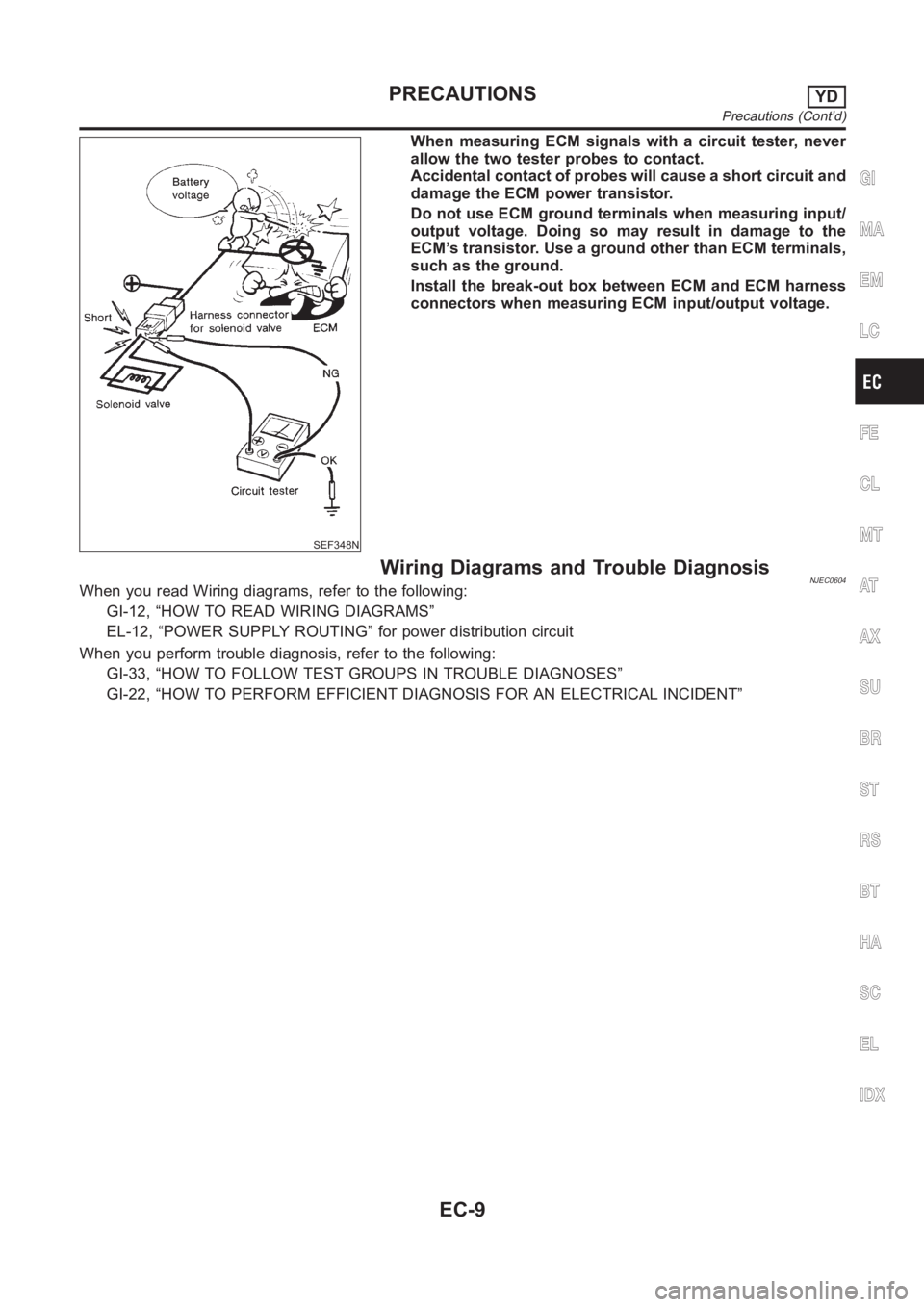
When measuring ECM signals with a circuit tester, never
allow the two tester probes to contact.
Accidental contact of probes will cause a short circuit and
damage the ECM power transistor.
Do not use ECM ground terminals when measuring input/
output voltage. Doing so may result in damage to the
ECM’s transistor. Use a ground other than ECM terminals,
such as the ground.
Install the break-out box between ECM and ECM harness
connectors when measuring ECM input/output voltage.
Wiring Diagrams and Trouble DiagnosisNJEC0604When you read Wiring diagrams, refer to the following:
GI-12, “HOW TO READ WIRING DIAGRAMS”
EL-12, “POWER SUPPLY ROUTING” for power distribution circuit
When you perform trouble diagnosis, refer to the following:
GI-33, “HOW TO FOLLOW TEST GROUPS IN TROUBLE DIAGNOSES”
GI-22, “HOW TO PERFORM EFFICIENT DIAGNOSIS FOR AN ELECTRICAL INCIDENT”
GI
MA
EM
LC
FE
CL
MT
AT
AX
SU
BR
ST
RS
BT
HA
SC
EL
IDX
PRECAUTIONSYD
Precautions (Cont’d)
EC-9
Page 1098 of 3189
SEF858S
Introduction
SEF233G
SEF234G
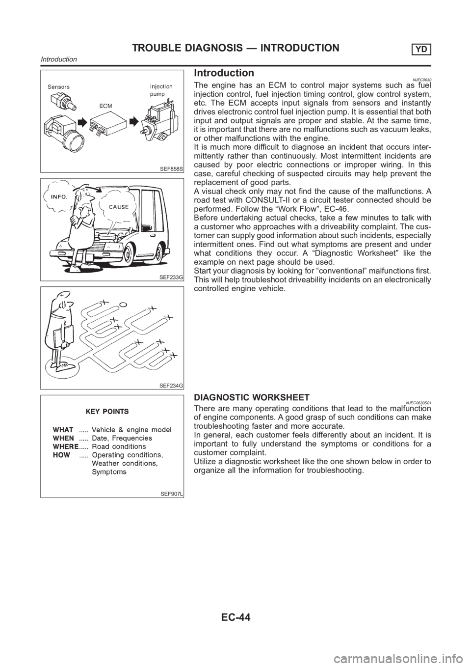
NJEC0630The engine has an ECM to control major systems such as fuel
injection control, fuel injection timing control, glow control system,
etc. The ECM accepts input signals from sensors and instantly
drives electronic control fuel injection pump. It is essential that both
input and output signals are proper and stable. At the same time,
it is important that there are no malfunctions such as vacuum leaks,
or other malfunctions with the engine.
It is much more difficult to diagnose an incident that occurs inter-
mittently rather than continuously. Most intermittent incidents are
caused by poor electric connections or improper wiring. In this
case, careful checking of suspected circuits may help prevent the
replacement of good parts.
A visual check only may not find the cause of the malfunctions. A
road test with CONSULT-II or a circuit tester connected should be
performed. Follow the “Work Flow”, EC-46.
Before undertaking actual checks, take a few minutes to talk with
a customer who approaches with a driveability complaint. The cus-
tomer can supply good information about such incidents, especially
intermittent ones. Find out what symptoms are present and under
what conditions they occur. A “Diagnostic Worksheet” like the
example on next page should be used.
Start your diagnosis by looking for “conventional” malfunctions first.
This will help troubleshoot driveability incidents on an electronically
controlled engine vehicle.
SEF907L
DIAGNOSTIC WORKSHEETNJEC0630S01There are many operating conditions that lead to the malfunction
of engine components. A good grasp of such conditions can make
troubleshooting faster and more accurate.
In general, each customer feels differently about an incident. It is
important to fully understand the symptoms or conditions for a
customer complaint.
Utilize a diagnostic worksheet like the one shown below in order to
organize all the information for troubleshooting.
TROUBLE DIAGNOSIS — INTRODUCTIONYD
Introduction
EC-44
Page 1102 of 3189
Basic InspectionNJEC0632Precaution:
Perform Basic Inspection without electrical or mechanical
loads applied;
Headlamp switch is OFF,
On vehicles equipped with daytime light systems, set
lighting switch to the 1st position to light only small
lamps.
Air conditioner switch is OFF,
Rear defogger switch is OFF,
Steering wheel is in the straight-ahead position, etc.
1 INSPECTION START
1. Check service records for any recent repairs that may indicate a relatedincident.
2. Check the current need for scheduled maintenance, especially for fuel filter and air cleaner filter. Refer to MA-4, “Peri-
odic Maintenance”.
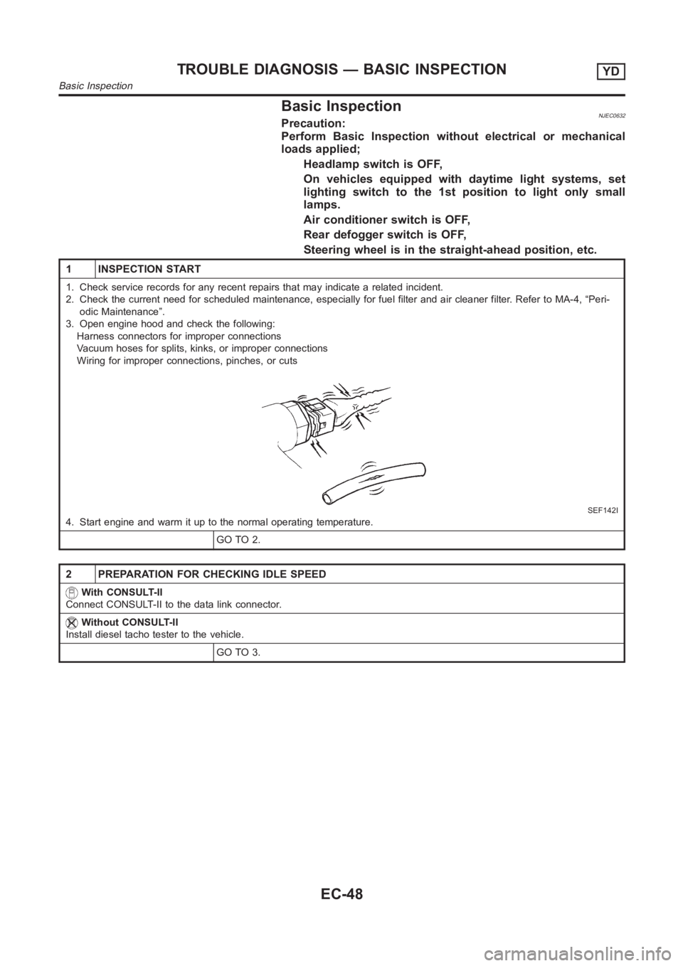
3. Open engine hood and check the following:
Harness connectors for improper connections
Vacuum hoses for splits, kinks, or improper connections
Wiring for improper connections, pinches, or cuts
SEF142I
4. Start engine and warm it up to the normal operating temperature.
GO TO 2.
2 PREPARATION FOR CHECKING IDLE SPEED
With CONSULT-II
Connect CONSULT-II to the data link connector.
Without CONSULT-II
Install diesel tacho tester to the vehicle.
GO TO 3.
TROUBLE DIAGNOSIS — BASIC INSPECTIONYD
Basic Inspection
EC-48
Page 1125 of 3189
DescriptionNJEC0637Intermittent incidents (I/I) may occur. In many cases, the incident resolves itself (the part or circuit function
returns to normal without intervention). It is important to realize that the symptoms described in the custom-
er’s complaint often do not recur on DTC visits. Realize also that the most frequent cause of I/I occurrences
is poor electrical connections. Because of this, the conditions under which the incident occurred may not be
clear. Therefore, circuit checks made as part of the standard diagnostic procedure may not indicate the spe-
cific malfunctioning area.
COMMON I/I REPORT SITUATIONSNJEC0637S01
STEP in Work Flow Situation
II The CONSULT-II is used. The SELF-DIAG RESULTS screen shows time data other than “0”.
III The symptom described by the customer does not recur.
IV DTC does not appear during the DTC Confirmation Procedure.
VI The Diagnostic Procedure for XXXX does not indicate the malfunctioningarea.
Diagnostic ProcedureNJEC0638
1 INSPECTION START
Erase DTCs. Refer to “HOW TO ERASE DTC”, EC-34.
GO TO 2.
2 CHECK GROUND TERMINALS
Check ground terminals for corroding or loose connection.
Refer to GI-23, “GROUND INSPECTION”.
OK or NG
OK GO TO 3.
NG Repair or replace.
3 SEARCH FOR ELECTRICAL INCIDENT
Perform GI-23, “Incident Simulation Tests”.
OK or NG
OKINSPECTION END
NG Repair or replace.
GI
MA
EM
LC
FE
CL
MT
AT
AX
SU
BR
ST
RS
BT
HA
SC
EL
IDX
TROUBLE DIAGNOSIS FOR INTERMITTENT INCIDENTYD
Description
EC-71
Page 1132 of 3189
SEF987W
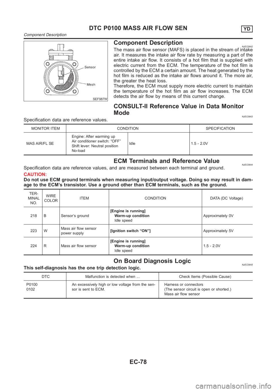
Component DescriptionNJEC0642The mass air flow sensor (MAFS) is placed in the stream of intake
air. It measures the intake air flow rate by measuring a part of the
entire intake air flow. It consists of a hot film that is supplied with
electric current from the ECM. The temperature of the hot film is
controlled by the ECM a certain amount. The heat generated by the
hot film is reduced as the intake air flows around it. The more air,
the greater the heat loss.
Therefore, the ECM must supply more electric current to maintain
the temperature of the hot film as air flow increases. The ECM
detects the air flow by means of this current change.
CONSULT-II Reference Value in Data Monitor
Mode
NJEC0643Specification data are reference values.
MONITOR ITEM CONDITION SPECIFICATION
MAS AIR/FL SEEngine: After warming up
Air conditioner switch: “OFF”
Shift lever: Neutral position
No-loadIdle 1.5 - 2.0V
ECM Terminals and Reference ValueNJEC0644Specification data are reference values, and are measured between each terminal and ground.
CAUTION:
Do not use ECM ground terminals when measuring input/output voltage. Doing so may result in dam-
age to the ECM’s transistor. Use a ground other than ECM terminals, such as the ground.
TER-
MINAL
NO.WIRE
COLORITEM CONDITION DATA (DC Voltage)
218 B Sensor’s ground[Engine is running]
Warm-up condition
Idle speedApproximately 0V
223 WMass air flow sensor
power supply[Ignition switch “ON”]Approximately 5V
224 R Mass air flow sensor[Engine is running]
Warm-up condition
Idle speed1.5 - 2.0V
On Board Diagnosis LogicNJEC0645This self-diagnosis has the one trip detection logic.
DTC Malfunction is detected when ... Check Items (Possible Cause)
P0100
0102An excessively high or low voltage from the sen-
sor is sent to ECM.Harness or connectors
(The sensor circuit is open or shorted.)
Mass air flow sensor
DTC P0100 MASS AIR FLOW SENYD
Component Description
EC-78
Page 1138 of 3189
SEF594K
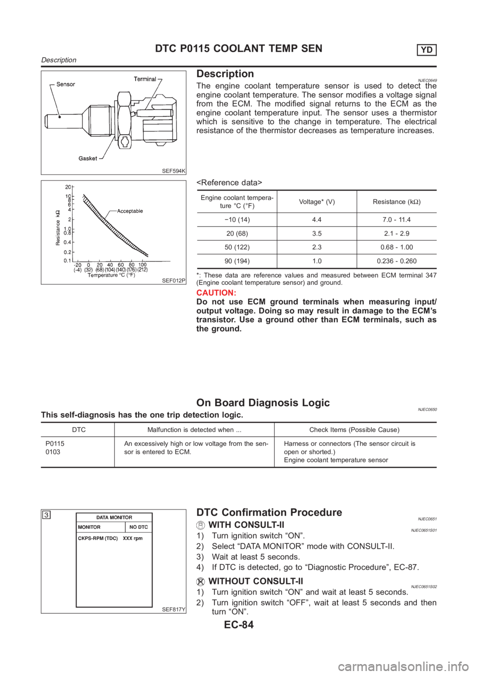
DescriptionNJEC0649The engine coolant temperature sensor is used to detect the
engine coolant temperature. The sensor modifies a voltage signal
from the ECM. The modified signal returns to the ECM as the
engine coolant temperature input. The sensor uses a thermistor
which is sensitive to the change in temperature. The electrical
resistance of the thermistor decreases as temperature increases.
SEF012P
Engine coolant tempera-
ture °C (°F)Voltage* (V) Resistance (kΩ)
−10 (14) 4.4 7.0 - 11.4
20 (68) 3.5 2.1 - 2.9
50 (122) 2.3 0.68 - 1.00
90 (194) 1.0 0.236 - 0.260
*: These data are reference values and measured between ECM terminal 347
(Engine coolant temperature sensor) and ground.
CAUTION:
Do not use ECM ground terminals when measuring input/
output voltage. Doing so may result in damage to the ECM’s
transistor. Use a ground other than ECM terminals, such as
the ground.
On Board Diagnosis LogicNJEC0650This self-diagnosis has the one trip detection logic.
DTC Malfunction is detected when ... Check Items (Possible Cause)
P0115
0103An excessively high or low voltage from the sen-
sor is entered to ECM.Harness or connectors (The sensor circuit is
open or shorted.)
Engine coolant temperature sensor
SEF817Y
DTC Confirmation ProcedureNJEC0651WITH CONSULT-IINJEC0651S011) Turn ignition switch “ON”.
2) Select “DATA MONITOR” mode with CONSULT-II.
3) Wait at least 5 seconds.
4) If DTC is detected, go to “Diagnostic Procedure”, EC-87.
WITHOUT CONSULT-IINJEC0651S021) Turn ignition switch “ON” and wait at least 5 seconds.
2) Turn ignition switch “OFF”, wait at least 5 seconds and then
turn “ON”.
DTC P0115 COOLANT TEMP SENYD
Description
EC-84