Page 1162 of 3189
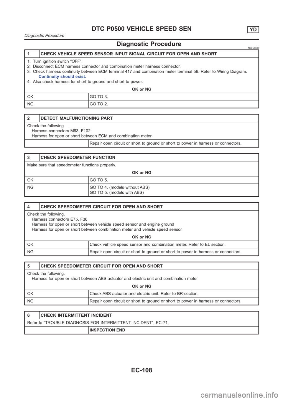
Diagnostic ProcedureNJEC0659
1 CHECK VEHICLE SPEED SENSOR INPUT SIGNAL CIRCUIT FOR OPEN AND SHORT
1. Turn ignition switch “OFF”.
2. Disconnect ECM harness connector and combination meter harness connector.
3. Check harness continuity between ECM terminal 417 and combination meter terminal 56. Refer to Wiring Diagram.
Continuity should exist.
4. Also check harness for short to ground and short to power.
OK or NG
OK GO TO 3.
NG GO TO 2.
2 DETECT MALFUNCTIONING PART
Check the following.
Harness connectors M63, F102
Harness for open or short between ECM and combination meter
Repair open circuit or short to ground or short to power in harness or connectors.
3 CHECK SPEEDOMETER FUNCTION
Make sure that speedometer functions properly.
OK or NG
OK GO TO 5.
NG GO TO 4. (models without ABS)
GO TO 5. (models with ABS)
4 CHECK SPEEDOMETER CIRCUIT FOR OPEN AND SHORT
Check the following.
Harness connectors E75, F36
Harness for open or short between vehicle speed sensor and engine ground
Harness for open or short between combination meter and vehicle speed sensor
OK or NG
OK Check vehicle speed sensor and combination meter. Refer to EL section.
NG Repair open circuit or short to ground or short to power in harness or connectors.
5 CHECK SPEEDOMETER CIRCUIT FOR OPEN AND SHORT
Check the following.
Harness for open or short between ABS actuator and electric unit and combination meter
OK or NG
OK Check ABS actuator and electric unit. Refer to BR section.
NG Repair open circuit or short to ground or short to power in harness or connectors.
6 CHECK INTERMITTENT INCIDENT
Refer to “TROUBLE DIAGNOSIS FOR INTERMITTENT INCIDENT”, EC-71.
INSPECTION END
DTC P0500 VEHICLE SPEED SENYD
Diagnostic Procedure
EC-108
Page 1238 of 3189
2 CHECK BATTERY AND ALTERNATOR
Check that the proper type of battery and alternator is installed.
Refer to SC-37, “Battery” and SC-38, “Alternator”.
OK or NG
OK GO TO 5.
NG Replace with a proper one.
3 CHECK JUMPER CABLES INSTALLATION
Check that the jumper cables are connected in the correct sequence.
SEF439Z
OK or NG
OK GO TO 4.
NG Reconnect jumper cables properly.
4 CHECK BATTERY FOR BOOSTER
Check that the battery for the booster is a 12V battery.
OK or NG
OK GO TO 5.
NG Change the vehicle for booster.
5 PERFORM DTC CONFIRMATION PROCEDURE AGAIN
Perform “DTC Confirmation Procedure”, EC-183, again.
OK or NG
OK GO TO 6.
NG Replace ECM.
6 CHECK ELECTRICAL PARTS DAMAGE
Check the following for damage.
Wiring harness and harness connectors for burn
Fuses for short
OK or NG
OKINSPECTION END
NG Repair or replace malfunctioning part.
DTC P1660 BATTERY VOLTAGEYD
Diagnostic Procedure (Cont’d)
EC-184
Page 1251 of 3189
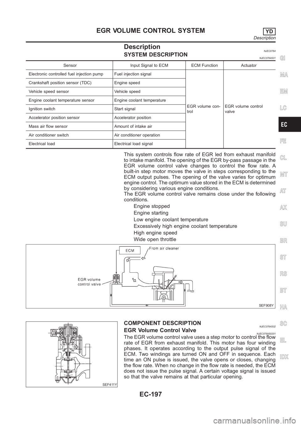
DescriptionNJEC0764SYSTEM DESCRIPTIONNJEC0764S01
Sensor Input Signal to ECM ECM Function Actuator
Electronic controlled fuel injection pump Fuel injection signal
EGR volume con-
trolEGR volume control
valve Crankshaft position sensor (TDC) Engine speed
Vehicle speed sensor Vehicle speed
Engine coolant temperature sensor Engine coolant temperature
Ignition switch Start signal
Accelerator position sensor Accelerator position
Mass air flow sensor Amount of intake air
Air conditioner switch Air conditioner operation
Electrical load Electrical load signal
This system controls flow rate of EGR led from exhaust manifold
to intake manifold. The opening of the EGR by-pass passage in the
EGR volume control valve changes to control the flow rate. A
built-in step motor moves the valve in steps corresponding to the
ECM output pulses. The opening of the valve varies for optimum
engine control. The optimum value stored in the ECM is determined
by considering various engine conditions.
The EGR volume control valve remains close under the following
conditions.
Engine stopped
Engine starting
Low engine coolant temperature
Excessively high engine coolant temperature
High engine speed
Wide open throttle
SEF908Y
SEF411Y
COMPONENT DESCRIPTIONNJEC0764S02EGR Volume Control ValveNJEC0764S0201The EGR volume control valve uses a step motor to control the flow
rate of EGR from exhaust manifold. This motor has four winding
phases. It operates according to the output pulse signal of the
ECM. Two windings are turned ON and OFF in sequence. Each
time an ON pulse is issued, the valve opens or closes, changing
the flow rate. When no change in the flow rate is needed, the ECM
does not issue the pulse signal. A certain voltage signal is issued
so that the valve remains at that particular opening.
GI
MA
EM
LC
FE
CL
MT
AT
AX
SU
BR
ST
RS
BT
HA
SC
EL
IDX
EGR VOLUME CONTROL SYSTEMYD
Description
EC-197
Page 1271 of 3189
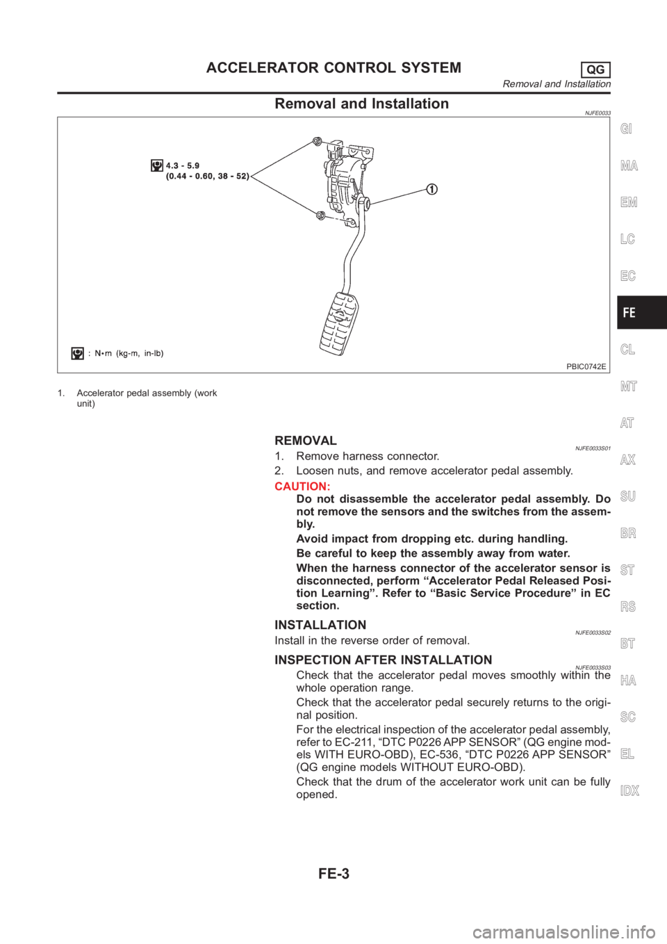
Removal and InstallationNJFE0033
PBIC0742E
1. Accelerator pedal assembly (work
unit)
REMOVALNJFE0033S011. Remove harness connector.
2. Loosen nuts, and remove accelerator pedal assembly.
CAUTION:
Do not disassemble the accelerator pedal assembly. Do
not remove the sensors and the switches from the assem-
bly.
Avoid impact from dropping etc. during handling.
Be careful to keep the assembly away from water.
When the harness connector of the accelerator sensor is
disconnected, perform “Accelerator Pedal Released Posi-
tion Learning”. Refer to “Basic Service Procedure” in EC
section.
INSTALLATIONNJFE0033S02Install in the reverse order of removal.
INSPECTION AFTER INSTALLATIONNJFE0033S03Check that the accelerator pedal moves smoothly within the
whole operation range.
Check that the accelerator pedal securely returns to the origi-
nal position.
For the electrical inspection of the accelerator pedal assembly,
refer to EC-211, “DTC P0226 APP SENSOR” (QG engine mod-
els WITH EURO-OBD), EC-536, “DTC P0226 APP SENSOR”
(QG engine models WITHOUT EURO-OBD).
Check that the drum of the accelerator work unit can be fully
opened.
GI
MA
EM
LC
EC
CL
MT
AT
AX
SU
BR
ST
RS
BT
HA
SC
EL
IDX
ACCELERATOR CONTROL SYSTEMQG
Removal and Installation
FE-3
Page 1274 of 3189
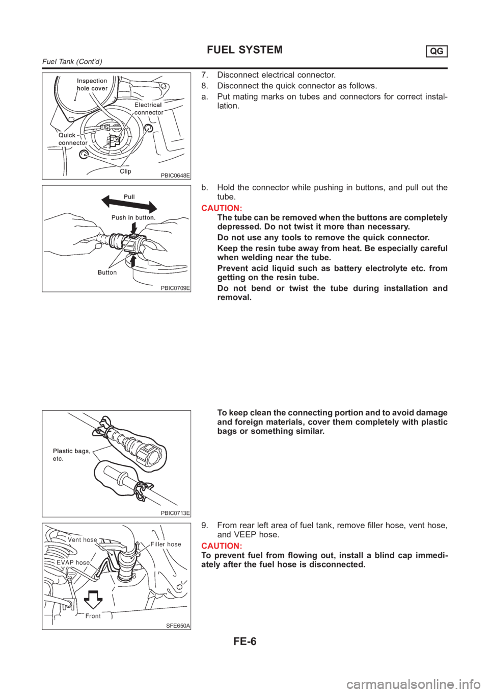
PBIC0648E
7. Disconnect electrical connector.
8. Disconnect the quick connector as follows.
a. Put mating marks on tubes and connectors for correct instal-
lation.
PBIC0709E
b. Hold the connector while pushing in buttons, and pull out the
tube.
CAUTION:
The tube can be removed when the buttons are completely
depressed. Do not twist it more than necessary.
Do not use any tools to remove the quick connector.
Keep the resin tube away from heat. Be especially careful
when welding near the tube.
Prevent acid liquid such as battery electrolyte etc. from
getting on the resin tube.
Do not bend or twist the tube during installation and
removal.
PBIC0713E
To keep clean the connecting portion and to avoid damage
and foreign materials, cover them completely with plastic
bags or something similar.
SFE650A
9. From rear left area of fuel tank, remove filler hose, vent hose,
and VEEP hose.
CAUTION:
To prevent fuel from flowing out, install a blind cap immedi-
ately after the fuel hose is disconnected.
FUEL SYSTEMQG
Fuel Tank (Cont’d)
FE-6
Page 1276 of 3189
Fuel Pump, Fuel Level Sensor Unit and Fuel
Filter
NJFE0007
YFE030
JFE613A
REMOVALNJFE0007S011. Release fuel pressure from fuel line.
Refer to EC-34, “Fuel Pressure Release”.
2. Disconnect battery ground cable.
3. Open fuel filler lid and filler cap.
4. Remove rear seat cushion. Refer to BT-59, “Removal and
Installation”.
5. Remove inspection hole cover under the rear seat.
PBIC0648E
6. Disconnect electrical connector.
7. Disconnect the quick connectors.
For disconnect of quick connectors, refer to step 8. of “Fuel
Tank Removal”.
FUEL SYSTEMQG
Fuel Pump, Fuel Level Sensor Unit and Fuel Filter
FE-8
Page 1287 of 3189
JFE613A
SFE600A
SFE601A
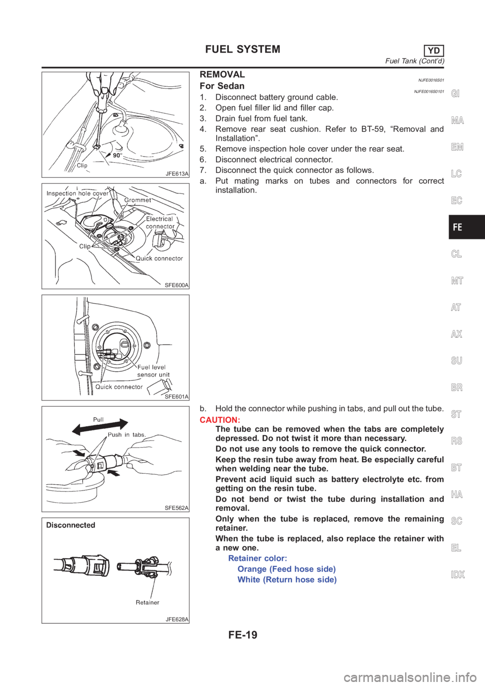
REMOVALNJFE0016S01For SedanNJFE0016S01011. Disconnect battery ground cable.
2. Open fuel filler lid and filler cap.
3. Drain fuel from fuel tank.
4. Remove rear seat cushion. Refer to BT-59, “Removal and
Installation”.
5. Remove inspection hole cover under the rear seat.
6. Disconnect electrical connector.
7. Disconnect the quick connector as follows.
a. Put mating marks on tubes and connectors for correct
installation.
SFE562A
JFE628A
b. Hold the connector while pushing in tabs, and pull out the tube.
CAUTION:
The tube can be removed when the tabs are completely
depressed. Do not twist it more than necessary.
Do not use any tools to remove the quick connector.
Keep the resin tube away from heat. Be especially careful
when welding near the tube.
Prevent acid liquid such as battery electrolyte etc. from
getting on the resin tube.
Do not bend or twist the tube during installation and
removal.
Only when the tube is replaced, remove the remaining
retainer.
When the tube is replaced, also replace the retainer with
a new one.
Retainer color:
Orange (Feed hose side)
White (Return hose side)
GI
MA
EM
LC
EC
CL
MT
AT
AX
SU
BR
ST
RS
BT
HA
SC
EL
IDX
FUEL SYSTEMYD
Fuel Tank (Cont’d)
FE-19
Page 1289 of 3189
JFE613A
SFE639A
SFE640A
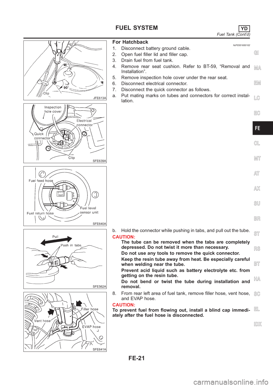
For HatchbackNJFE0016S01021. Disconnect battery ground cable.
2. Open fuel filler lid and filler cap.
3. Drain fuel from fuel tank.
4. Remove rear seat cushion. Refer to BT-59, “Removal and
Installation”.
5. Remove inspection hole cover under the rear seat.
6. Disconnect electrical connector.
7. Disconnect the quick connector as follows.
a. Put mating marks on tubes and connectors for correct instal-
lation.
SFE562A
b. Hold the connector while pushing in tabs, and pull out the tube.
CAUTION:
The tube can be removed when the tabs are completely
depressed. Do not twist it more than necessary.
Do not use any tools to remove the quick connector.
Keep the resin tube away from heat. Be especially careful
when welding near the tube.
Prevent acid liquid such as battery electrolyte etc. from
getting on the resin tube.
Do not bend or twist the tube during installation and
removal.
SFE641A
8. From rear left area of fuel tank, remove filler hose, vent hose,
and EVAP hose.
CAUTION:
To prevent fuel from flowing out, install a blind cap immedi-
ately after the fuel hose is disconnected.
GI
MA
EM
LC
EC
CL
MT
AT
AX
SU
BR
ST
RS
BT
HA
SC
EL
IDX
FUEL SYSTEMYD
Fuel Tank (Cont’d)
FE-21