2003 NISSAN ALMERA N16 ELECTRICAL SYSTEME
[x] Cancel search: ELECTRICAL SYSTEMEPage 1 of 3189
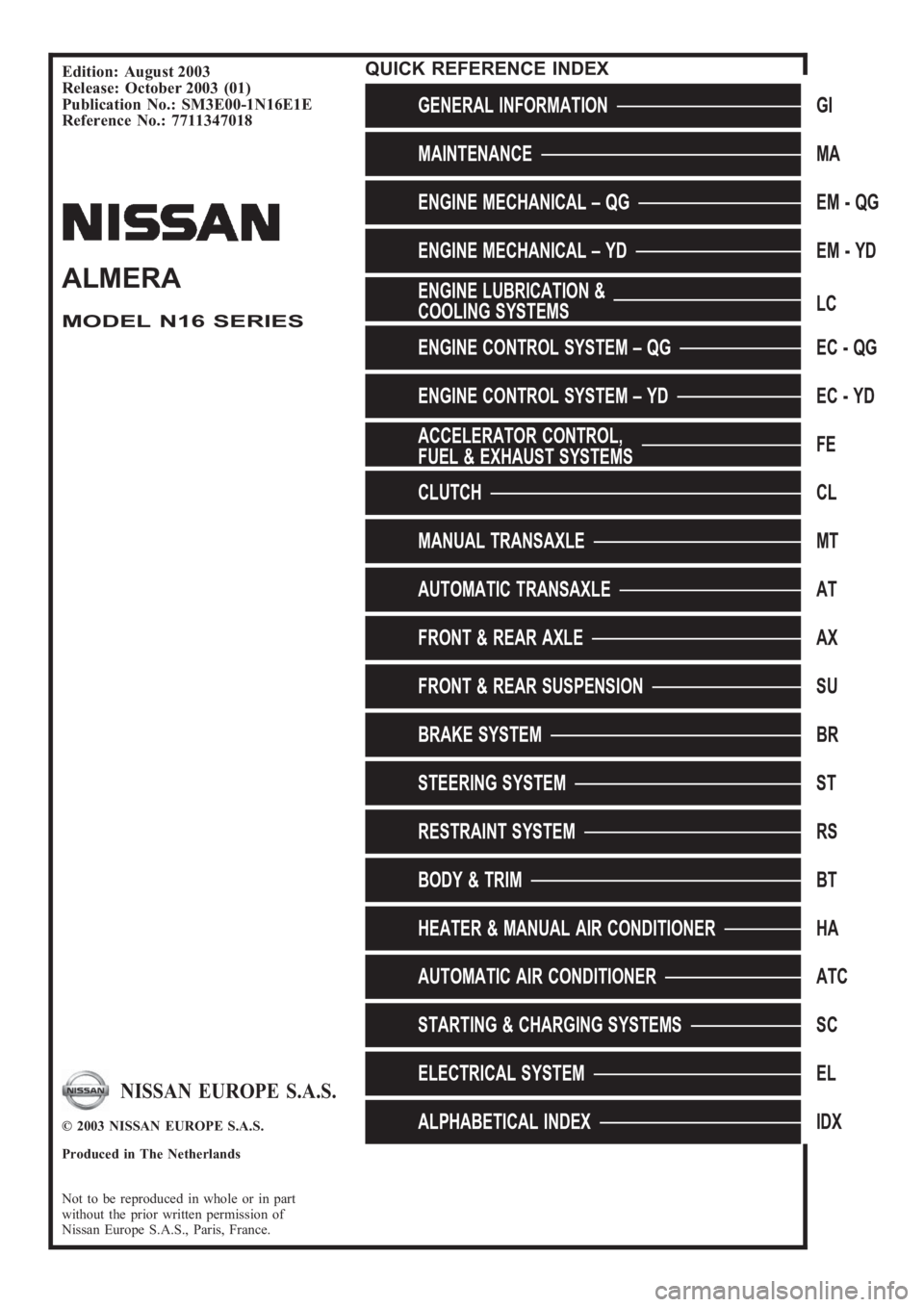
Edition: August 2003
Release: October 2003 (01)
Publication No.: SM3E00-1N16E1E
Reference No.: 7711347018
GENERAL INFORMATIONGI
MAINTENANCEMA
ENGINE MECHANICAL – QGEM-QG
ENGINE MECHANICAL – YDEM-YD
ENGINE LUBRICATION &
COOLING SYSTEMSLC
ENGINE CONTROL SYSTEM – QGEC - QG
ENGINE CONTROL SYSTEM – YDEC - YD
ACCELERATOR CONTROL,
FUEL & EXHAUST SYSTEMSFE
CLUTCHCL
MANUAL TRANSAXLEMT
AUTOMATIC TRANSAXLEAT
FRONT & REAR AXLEAX
FRONT & REAR SUSPENSIONSU
BRAKE SYSTEMBR
STEERING SYSTEMST
RESTRAINT SYSTEMRS
BODY & TRIMBT
HEATER & MANUAL AIR CONDITIONERHA
AUTOMATIC AIR CONDITIONERATC
STARTING & CHARGING SYSTEMSSC
ELECTRICAL SYSTEMEL
ALPHABETICAL INDEXIDX
ALMERA
MODEL N16 SERIES
NISSAN EUROPE S.A.S.
© 2003 NISSAN EUROPE S.A.S.
Produced in The Netherlands
Not to be reproduced in whole or in part
without the prior written permission of
Nissan Europe S.A.S., Paris, France.
QUICK REFERENCE INDEX
Page 353 of 3189
![NISSAN ALMERA N16 2003 Electronic Repair Manual ENGINE CONTROL SYSTEM
EC-23
[QG (WITH EURO-OBD)]
C
D
E
F
G
H
I
J
K
L
MA
EC
System ChartEBS00K34
*1: This sensor is not used to control the engine system under normal conditions.
*2: The signals are se](/manual-img/5/57350/w960_57350-352.png "NISSAN ALMERA N16 2003 Electronic Repair Manual ENGINE CONTROL SYSTEM
EC-23
[QG (WITH EURO-OBD)]
C
D
E
F
G
H
I
J
K
L
MA
EC
System ChartEBS00K34
*1: This sensor is not used to control the engine system under normal conditions.
*2: The signals are se")
ENGINE CONTROL SYSTEM
EC-23
[QG (WITH EURO-OBD)]
C
D
E
F
G
H
I
J
K
L
MA
EC
System ChartEBS00K34
*1: This sensor is not used to control the engine system under normal conditions.
*2: The signals are sent to the ECM through CAN communication line.
*3: The output signals are sent from the ECM through CAN communication line.
Multiport Fuel Injection (MFI) SystemEBS00K35
INPUT/OUTPUT SIGNAL CHART
*1: Under normal conditions, this sensor is not for engine control operation.
*2: This signal is sent to the ECM through CAN communication line.
*3: ECM determines the start signal status by the signals of engine speed and battery voltage.
SYSTEM DESCRIPTION
The amount of fuel injected from the fuel injector is determined by the ECM. The ECM controls the length of
time the valve remains open (injection pulse duration). The amount of fuel injected is a program value in the
Input (Sensor) ECM Function Output (Actuator)
●Camshaft position sensor (PHASE)
●Crankshaft position sensor (POS)
●Mass air flow sensor
●Engine coolant temperature sensor
●Heated oxygen sensor 1
●Throttle position sensor
●Accelerator pedal position sensor
●Park/neutral position (PNP) switch
●Intake air temperature sensor
●Power steering pressure sensor
●Ignition switch
●Stop lamp switch
●Battery voltage
●Knock sensor
●Refrigerant pressure sensor
●Heated oxygen sensor 2*1
●TCM (Transmission control module)*2
●Air conditioner switch*2
●Vehicle speed signal*2
●Electrical load signal*2
Fuel injection & mixture ratio control Fuel injectors
Electronic ignition system Power transistor
Fuel pump control Fuel pump relay
On board diagnostic system
MI (On the instrument panel)
*3
Intake valve timing controlIntake valve timing control solenoid
valve
Heated oxygen sensor 1 heater control Heated oxygen sensor 1 heater
Heated oxygen sensor 2 heater control Heated oxygen sensor 2 heater
EVAP canister purge flow controlEVAP canister purge volume control
solenoid valve
Air conditioning cut control
Air conditioner relay
*3
Cooling fan control
Cooling fan relay*3
Sensor Input Signal to ECM ECM Function Actuator
Crankshaft position sensor (POS)
Camshaft position sensor (PHASE)Engine speed
*3 and piston position
Fuel injection & mixture
ratio controlFuel injectors Mass air flow sensor Amount of intake air
Engine coolant temperature sensor Engine coolant temperature
Heated oxygen sensor 1 Density of oxygen in exhaust gas
Throttle position sensor Throttle position
Accelerator pedal position sensor Accelerator pedal position
Park/neutral position (PNP) switch Gear position
Knock sensor Engine knocking condition
Battery
Battery voltage
*3
Power steering pressure sensor Power steering operation
Heated oxygen sensor 2
*1Density of oxygen in exhaust gas
Vehicle speed signal
*2Vehicle speed
Air conditioner switch
*2Air conditioner operation
Page 747 of 3189
![NISSAN ALMERA N16 2003 Electronic Repair Manual ENGINE CONTROL SYSTEM
EC-417
[QG (WITHOUT EURO-OBD)]
C
D
E
F
G
H
I
J
K
L
MA
EC
System ChartEBS00KEB
*1: This sensor is not used to control the engine system under normal conditions.
*2: The signals ar](/manual-img/5/57350/w960_57350-746.png "NISSAN ALMERA N16 2003 Electronic Repair Manual ENGINE CONTROL SYSTEM
EC-417
[QG (WITHOUT EURO-OBD)]
C
D
E
F
G
H
I
J
K
L
MA
EC
System ChartEBS00KEB
*1: This sensor is not used to control the engine system under normal conditions.
*2: The signals ar")
ENGINE CONTROL SYSTEM
EC-417
[QG (WITHOUT EURO-OBD)]
C
D
E
F
G
H
I
J
K
L
MA
EC
System ChartEBS00KEB
*1: This sensor is not used to control the engine system under normal conditions.
*2: The signals are sent to the ECM through CAN communication line.
*3: The output signals are sent from the ECM through CAN communication line.
Multiport Fuel Injection (MFI) SystemEBS00KEC
INPUT/OUTPUT SIGNAL CHART
*1: Under normal conditions, this sensor is not for engine control operation.
*2: This signal is sent to the ECM through CAN communication line.
*3: The ECM determines the start signal status by the signals of engine speed and battery voltage.
SYSTEM DESCRIPTION
The amount of fuel injected from the fuel injector is determined by the ECM. The ECM controls the length of
time the valve remains open (injection pulse duration). The amount of fuel injected is a program value in the
Input (Sensor) ECM Function Output (Actuator)
●Camshaft position sensor (PHASE)
●Crankshaft position sensor (POS)
●Mass air flow sensor
●Engine coolant temperature sensor
●Heated oxygen sensor 1
●Throttle position sensor
●Accelerator pedal position sensor
●Park/neutral position (PNP) switch
●Intake air temperature sensor
●Power steering pressure sensor
●Ignition switch
●Stop lamp switch
●Battery voltage
●Knock sensor
●Refrigerant pressure sensor
●Heated oxygen sensor 2*1
●TCM (Transmission control module)*2
●Air conditioner switch*2
●Vehicle speed signal*2
●Electrical load signal*2
Fuel injection & mixture ratio control Fuel injectors
Electronic ignition system Power transistor
Fuel pump control Fuel pump relay
On board diagnostic system
MI (On the instrument panel)
*3
Intake valve timing controlIntake valve timing control solenoid
valve
Heated oxygen sensor 1 heater control Heated oxygen sensor 1 heater
Heated oxygen sensor 2 heater control Heated oxygen sensor 2 heater
EVAP canister purge flow controlEVAP canister purge volume control
solenoid valve
Air conditioning cut control
Air conditioner relay
*3
Cooling fan control
Cooling fan relays*3
Sensor Input Signal to ECM ECM function Actuator
Crankshaft position sensor (POS)
Camshaft position sensor (PHASE)Engine speed
*3 and piston position
Fuel injection & mix-
ture ratio controlFuel injectors Mass air flow sensor Amount of intake air
Engine coolant temperature sensor Engine coolant temperature
Heated oxygen sensor 1 Density of oxygen in exhaust gas
Throttle position sensor Throttle position
Accelerator pedal position sensor Accelerator pedal position
Park/neutral position (PNP) switch Gear position
Knock sensor Engine knocking condition
Battery
Battery voltage
*3
Power steering pressure sensor Power steering operation
Heated oxygen sensor 2
*1Density of oxygen in exhaust gas
Vehicle speed signal
*2Vehicle speed
Air conditioner switch
*2Air conditioner operation
Page 2578 of 3189
![NISSAN ALMERA N16 2003 Electronic Repair Manual Warning indicatorsWarning lamps in
instrument panelWarning detection and cancel conditions Cases of malfunction
DOOR OPEN DoorDetection conditionVehicle is running [approx. 5
km/h (3 MPH) or faster] a](/manual-img/5/57350/w960_57350-2577.png "NISSAN ALMERA N16 2003 Electronic Repair Manual Warning indicatorsWarning lamps in
instrument panelWarning detection and cancel conditions Cases of malfunction
DOOR OPEN DoorDetection conditionVehicle is running [approx. 5
km/h (3 MPH) or faster] a")
Warning indicatorsWarning lamps in
instrument panelWarning detection and cancel conditions Cases of malfunction
DOOR OPEN DoorDetection conditionVehicle is running [approx. 5
km/h (3 MPH) or faster] and door
ajar of any of the doors is
detected.Doorisopen
Cancel conditionVehicle is stopped and all the
doors lock.
ABS ABSDetection conditionWarning lamp ON signal is
detected when engine is running.
ABS control system mal-
function
Cancel conditionWarning lamp OFF signal is
detected.
ESP ELECTRONIC
CONTROL SYSTEMESPDetection conditionWarning lamp ON signal is
detected when engine is running.
ESP system malfunction
Cancel conditionWarning lamp OFF signal is
detected.
CVT ELECTRONIC
CONTROL SYSTEMCVTDetection conditionWarning lamp ON signal is
detected after ignition switch is
turned ON.
TCM system malfunction
Cancel conditionWarning lamp OFF signal is
detected.
CRUISE CONTROL
SYSTEMCRUISEDetection conditionWarning lamp ON signal is
detected after ignition switch is
turned ON.
ICC system malfunction
Cancel conditionWarning lamp OFF signal is
detected.
Precautions for Display Unit ReplacementNJEL0572Record the following memorized contents before replacing the control unit.
Preset frequency
Area for indicating station, selection of overlapped stations
Program status
Volume balance memory set values
Equalizer memory set values
Brightness of light when ON/OFF
Dimming switching
Display color switching
Replace the display unit after disconnecting both battery cables.
Component Parts and Harness Connector and
Harness Connector Location
NJEL0573For details, refer to “ELECTRICAL UNIT LOCATION” (EL-543) and “HARNESS LAYOUT” (EL-550).
LCD DISPLAY
System Description (Cont’d)
EL-242