2003 NISSAN ALMERA N16 Electric
[x] Cancel search: ElectricPage 1292 of 3189
JFE613A
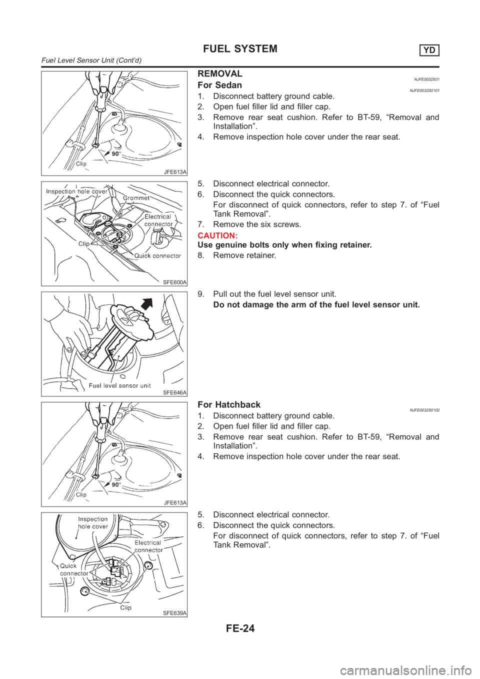
REMOVALNJFE0032S01For SedanNJFE0032S01011. Disconnect battery ground cable.
2. Open fuel filler lid and filler cap.
3. Remove rear seat cushion. Refer to BT-59, “Removal and
Installation”.
4. Remove inspection hole cover under the rear seat.
SFE600A
5. Disconnect electrical connector.
6. Disconnect the quick connectors.
For disconnect of quick connectors, refer to step 7. of “Fuel
Tank Removal”.
7. Remove the six screws.
CAUTION:
Use genuine bolts only when fixing retainer.
8. Remove retainer.
SFE646A
9. Pull out the fuel level sensor unit.
Do not damage the arm of the fuel level sensor unit.
JFE613A
For HatchbackNJFE0032S01021. Disconnect battery ground cable.
2. Open fuel filler lid and filler cap.
3. Remove rear seat cushion. Refer to BT-59, “Removal and
Installation”.
4. Remove inspection hole cover under the rear seat.
SFE639A
5. Disconnect electrical connector.
6. Disconnect the quick connectors.
For disconnect of quick connectors, refer to step 7. of “Fuel
Tank Removal”.
FUEL SYSTEMYD
Fuel Level Sensor Unit (Cont’d)
FE-24
Page 1457 of 3189
AT-1
AUTOMATIC TRANSAXLE
C TRANSMISSION/TRANSAXLE
CONTENTS
D
E
F
G
H
I
J
K
L
M
SECTION
A
B
AT
AUTOMATIC TRANSAXLE
PRECAUTIONS .......................................................... 5
Precautions for Supplemental Restraint System
(SRS) “AIR BAG” and “SEAT BELT PRE-TEN-
SIONER” .................................................................. 5
Precautions for On Board Diagnostic (EURO-OBD)
System of A/T and Engine — Euro-OBD — ............. 5
Precautions for Trouble Diagnosis ........................... 5
Precautions for Harness Repair ............................... 5
Precautions .............................................................. 6
Service Notice or Precautions .................................. 7
Wiring Diagrams and Trouble Diagnosis .................. 8
PREPARATION ........................................................... 9
Special Service Tools ............................................... 9
Commercial Service Tools ...................................... 12
A/T FLUID ................................................................. 13
Checking A/T Fluid ................................................. 13
Changing A/T Fluid ............................................. ... 13
OVERALL SYSTEM ................................................. 14
A/T Electrical Parts Location .................................. 14
Circuit Diagram ...................................................... 15
Cross-Sectional View ............................................. 16
Hydraulic Control Circuit ........................................ 17
Shift Mechanism ..................................................... 18
Control System ....................................................... 27
Control Mechanism ................................................ 28
Control Valve .......................................................... 34
EURO-OBD
TROUBLE DIAGNOSIS — INDEX ........................... 35
Alphabetical & P No. Index for DTC ....................... 35
ON BOARD DIAGNOSTIC SYSTEM DESCRIP-
TION .......................................................................... 37
Introduction ............................................................ 37
EURO-OBD Function for A/T System .................... 37
One or Two Trip Detection Logic of EURO-OBD ... 37
EURO-OBD Diagnostic Trouble Code (DTC) ......... 37
Malfunction Indicator (MI) ....................................... 41
CONSULT-II ........................................................... 41
Diagnostic Procedure Without CONSULT-II ........... 50TROUBLE DIAGNOSIS — INTRODUCTION ........... 56
Introduction ............................................................. 56
Work Flow ............................................................... 60
TROUBLE DIAGNOSIS — BASIC INSPECTION .... 63
A/T Fluid Check ...................................................... 63
Stall Test ................................................................. 64
Line Pressure Test .................................................. 67
Road Test ............................................................... 68
TROUBLE DIAGNOSIS — GENERAL DESCRIP-
TION .......................................................................... 86
Symptom Chart ....................................................... 86
TCM Terminals and Reference Value ...................106
CAN COMMUNICATION .........................................109
System Description ...............................................109
CAN Communication Unit .....................................109
DTC P0705 PARK/NEUTRAL POSITION (PNP)
SWITCH ...................................................................111
Description .............................................................111
Wiring Diagram — AT — PNP/SW .......................113
Diagnostic Procedure ...........................................114
Component Inspection ..........................................116
DTC P0710 A/T FLUID TEMPERATURE SENSOR
CIRCUIT ..................................................................117
Description ............................................................117
Wiring Diagram — AT — FTS ..............................119
Diagnostic Procedure ...........................................120
Component Inspection ..........................................122
DTC P0720 VEHICLE SPEED SENSOR A/T (REV-
OLUTION SENSOR) ...............................................123
Description ............................................................123
Wiring Diagram — AT — VSSA/T ........................126
Diagnostic Procedure ...........................................127
DTC P0725 ENGINE SPEED SIGNAL ...................129
Description ............................................................129
Wiring Diagram — AT — ENGSS .........................130
Diagnostic Procedure ..........................................
.131
DTC P0731 A/T 1ST GEAR FUNCTION ................133
Description ............................................................133
Wiring Diagram — AT — 1ST ...............................136
Page 1459 of 3189
AT-3
D
E
F
G
H
I
J
K
L
MA
B
AT Line Pressure Test ............................................... 265
Road Test ............................................................. 266
TROUBLE DIAGNOSIS — GENERAL DESCRIP-
TION ........................................................................ 283
Symptom Chart .................................................... 283
TCM Terminals and Reference Value ................... 302
CAN COMMUNICATION ........................................ 305
System Description .............................................. 305
CAN Communication Unit .................................... 305
TROUBLE DIAGNOSES FOR SYMPTOMS .......... 307
Wiring Diagram — AT — NONDTC ...................... 307
1. O/D OFF Indicator Lamp Does Not Come On . 309
2. Engine Cannot Be Started In “P” and “N” Position . 309
3. In “P” Position, Vehicle Moves Forward Or Back-
ward When Pushed .............................................. 310
4. In “N” Position, Vehicle Moves .......................... 311
5. Large Shock. “N” → “R” Position ...................... 312
6. Vehicle Does Not Creep Backward In “R” Position . 313
7. Vehicle Does Not Creep Forward In “D”, “2” Or
“1” Position ........................................................... 316
8. Vehicle Cannot Be Started From D
1 ................. 317
9. A/T Does Not Shift: D
1→ D2 Or Does Not Kick
down: D
4→ D2 ..................................................... 320
10. A/T Does Not Shift: D
2→ D3 ......................... 322
11. A/T Does Not Shift: D
3→ D4 .......................... 324
12. A/T Does Not Perform Lock-up ...................... 326
13. A/T Does Not Hold Lock-up Condition ........... 326
14. Lock-up Is Not Released ................................ 328
15. Engine Speed Does Not Return To Idle (Light
Braking D
4→ D3 ) ................................................ 328
16. Vehicle Does Not Start From D
1 ..................... 330
17. A/T Does Not Shift: D
4→ D3 , When Overdrive
Control Switch “ON” → “OFF” .............................. 330
18. A/T Does Not Shift: D
3→ 22 , When Selector
Lever “D” → “2” Position ...................................... 331
19. A/T Does Not Shift: 2
2→ 11 , When Selector
Lever “2” → “1” Position ....................................... 332
20. Vehicle Does Not Decelerate By Engine Brake . 333
21. TCM Self-diagnosis Does Not Activate (PNP &
Overdrive Control Switches, and Throttle Position
Sensor Circuit Checks) ........................................ 333
ALL
MAIN POWER SUPPLY AND GROUND CIRCUIT . 340
Wiring Diagram — AT — MAIN ............................ 340
Diagnostic Procedure ........................................... 341
VEHICLE SPEED SENSOR - A/T (REVOLUTION
SENSOR) ................................................................ 343
Description ........................................................... 343
Wiring Diagram — AT — VSSAT ......................... 345
Diagnostic Procedure ........................................... 346
DTC VEHICLE SPEED SENSOR MTR .................. 348
Description ........................................................... 348
Wiring Diagram — AT — VSSMTR ...................... 350
Diagnostic Procedure ........................................... 351
ACCELE RATOR PEDAL POSITION (APP) SEN-
SOR ........................................................................ 352
Description ........................................................... 352Wiring Diagram — AT — TPS ..............................354
Diagnostic Procedure ...........................................355
SHIFT SOLENOID VALVE A ..................................357
Description ............................................................357
Wiring Diagram — AT — SSV/A ...........................359
Diagnostic Procedure ...........................................360
Component Inspection ..........................................360
SHIFT SOLENOID VALVE B ..................................362
Description ............................................................362
Wiring Diagram — AT — SSV/B ...........................364
Diagnostic Procedure ...........................................365
Component Inspection ..........................................365
OVERRUN CLUTCH SOLENOID VALVE ...............367
Description ............................................................367
Wiring Diagram — AT — OVRCSV ......................369
Diagnostic Procedure ...........................................370
Component Inspection ..........................................371
TORQUE CONVERTER CLUTCH SOLENOID
VALVE .....................................................................372
Description ............................................................372
Wiring Diagram — AT — TCV ..............................374
Diagnostic Procedure ...........................................375
Component Inspection ..........................................375
BATT/FLUID TEMP SEN (A/T FLUID TEMP SEN-
SOR CIRCUIT AND TCM POWER SOURCE) .......377
Description ............................................................377
Wiring Diagram — AT — BA/FTS .........................379
Diagnostic Procedure ...........................................380
Component Inspection ..........................................382
ENGINE SPEED SIGNAL .......................................383
Description ............................................................383
Wiring Diagram — AT — ENGSS .........................385
Diagnostic Procedure ...........................................386
LINE PRESSURE SOLENOID VALVE ...................388
Description ............................................................388
Wiring Diagram — AT — LPSV ............................390
Diagnostic Procedure ...........................................391
Component Inspection ..........................................393
CAN COMMUNICATION LINE ...............................395
Description ............................................................395
On Board Diagnosis Logic ....................................395
Self-Diagnosis Code Confirmation Procedure ......395
Wiring Diagram — AT — CAN ..............................396
Diagnostic Procedure ...........................................397
A/T SHIFT LOCK SYSTEM ....................................398
Description ............................................................398
Shift Lock System Electrical Parts Location .........398
Wiring Diagram — SHIFT — ................................399
Diagnostic Procedure ...........................................400
KEY INTERLOCK CABLE ......................................404
Components .........................................................404
Removal ...............................................................404
Installation ............................................................405
ON-VEHICLE SERVICE ..........................................406
Control Valve Assembly and Accumulators ..........406
Control Cable Adjustment .....................................408
Park/Neutral Position (PNP) Switch Adjustment ..408
Differential Side Oil Seal Replacement ................409
Revolution Sensor Replacement ..........................409
Page 1461 of 3189
PRECAUTIONS
AT-5
D
E
F
G
H
I
J
K
L
MA
B
AT
PRECAUTIONSPFP:00001
Precautions for Supplemental Restraint System (SRS) “AIR BAG” and “SEAT
BELT PRE-TENSIONER”
ECS007N3
The Supplemental Restraint System such as “AIR BAG” and “SEAT BELT PRE-TENSIONER”, used along
with a front seat belt, helps to reduce the risk or severity of injury to the driver and front passenger for certain
types of collision. Information necessary to service the system safely is included in the SRS and SB section of
this Service Manual.
WARNING:
●To avoid rendering the SRS inoperative, which could increase the risk of personal injury or death
in the event of a collision which would result in air bag inflation, all maintenance must be per-
formed by an authorized NISSAN/INFINITI dealer.
●Improper maintenance, including incorrect removal and installation of the SRS, can lead to per-
sonal injury caused by unintentional activation of the system. For removal of Spiral Cable and Air
Bag Module, see the SRS section.
●Do not use electrical test equipment on any circuit related to the SRS unless instructed to in this
Service Manual. SRS wiring harnesses can be identified by yellow and/or orange harness connec-
tors.
Precautions for On Board Diagnostic (EURO-OBD) System of A/T and Engine —
Euro-OBD —
ECS007N4
The ECM has an on board diagnostic system. It will light up the malfunction indicator (MI) to warn the driver of
a malfunction causing emission deterioration.
CAUTION:
●Be sure to turn the ignition switch “OFF” and disconnect the negative battery terminal before any
repair or inspection work. The open/short circuit of related switches, sensors, solenoid valves,
etc. will cause the MI to light up.
●Be sure to connect and lock the connectors securely after work. A loose (unlocked) connector will
cause the MI to light up due to an open circuit. (Be sure the connector is free from water, grease,
dirt, bent terminals, etc.)
●Be sure to route and secure the harnesses properly after work. Interference of the harness with a
bracket, etc. may cause the MI to light up due to a short circuit.
●Be sure to connect rubber tubes properly after work. A misconnected or disconnected rubber tube
may cause the MI to light up due to a malfunction of the EGR system or fuel injection system, etc.
●Be sure to erase the unnecessary malfunction information (repairs completed) from the TCM and
ECM before returning the vehicle to the customer.
Precautions for Trouble DiagnosisECS007N5
CAN SYSTEM
●Do not apply voltage of 7.0V or higher to the measurement terminals.
●Use the tester with its open terminal voltage being 7.0V or less.
Precautions for Harness RepairECS007N6
CAN SYSTEM
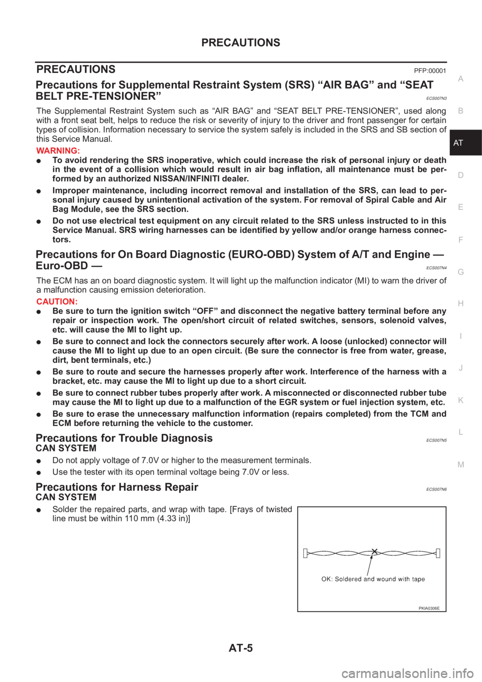
●Solder the repaired parts, and wrap with tape. [Frays of twisted
line must be within 110 mm (4.33 in)]
PKIA0306E
Page 1463 of 3189
PRECAUTIONS
AT-7
D
E
F
G
H
I
J
K
L
MA
B
AT
●After performing each TROUBLE DIAGNOSIS, perform
“DTC (Diagnostic Trouble Code) CONFIRMATION PROCE-
DURE”.
The DTC should not be displayed in the “DTC CONFIRMA-
TION PROCEDURE” if the repair is completed.
●Before proceeding with disassembly, thoroughly clean the out-
side of the transaxle. It is important to prevent the internal parts
from becoming contaminated by dirt or other foreign matter.
●Disassembly should be done in a clean work area.
●Use lint-free cloth or towels for wiping parts clean. Common
shop rags can leave fibers that could interfere with the operation
of the transaxle.
●Place disassembled parts in order for easier and proper assembly.
●All parts should be carefully cleaned with a general purpose, non-flammable solvent before inspection or
reassembly.
●Gaskets, seals and O-rings should be replaced any time the transaxle is disassembled.
●It is very important to perform functional tests whenever they are indicated.
●The valve body contains precision parts and requires extreme care when parts are removed and serviced.
Place disassembled valve body parts in order for easier and proper assembly. Care will also prevent
springs and small parts from becoming scattered or lost.
●Properly installed valves, sleeves, plugs, etc. will slide along bores in valve body under their own weight.
●Before assembly, apply a coat of recommended ATF to all parts. Apply petroleum jelly to protect O-rings
and seals, or hold bearings and washers in place during assembly. Do not use grease.
●Extreme care should be taken to avoid damage to O-rings, seals and gaskets when assembling.
●After overhaul, refill the transaxle with new ATF.
●When the A/T drain plug is removed, only some of the fluid is drained. Old A/T fluid will remain in torque
converter and ATF cooling system.
Always follow the procedures under AT-13, "
Changing A/T Fluid" when changing A/T fluid.
Service Notice or PrecautionsECS007N8
FA I L - S A F E
The TCM has an electronic Fail-Safe (limp home mode). This allows the vehicle to be driven even if a major
electrical input/output device circuit is damaged.
Under Fail-Safe, the vehicle always runs in third gear, even with a shift lever position of “1”, “2” or “D”. The cus-
tomer may complain of sluggish or poor acceleration.
When the ignition key is turned “ON” following Fail-Safe operation, O/D OFF indicator lamp blinks for about 8
seconds. Refer to AT- 2 5 0 , "
Diagnostic Procedure Without CONSULT-II" (EXCEPT FOR EURO-OBD) or AT-
51, "TCM SELF-DIAGNOSTIC PROCEDURE (NO TOOLS)" (EURO-OBD).
The blinking of the O/D OFF indicator lamp for about 8 seconds will appear only once and be cleared. The
customer may resume normal driving conditions.
Always follow the “Work Flow”, refer to AT- 2 5 9
(EXCEPT FOR EURO-OBD) or AT- 6 0 (EURO-OBD).
The SELF-DIAGNOSIS results will be as follows:
●The first SELF-DIAGNOSIS will indicate damage to the vehicle speed sensor or the revolution sensor.
●During the next SELF-DIAGNOSIS, performed after checking the sensor, no damages will be indicated.
TORQUE CONVERTER SERVICE
The torque converter should be replaced under any of the following conditions:
●External leaks in the hub weld area.
●Converter hub is scored or damaged.
●Converter pilot is broken, damaged or fits poorly into crankshaft.
●Steel particles are found after flushing the cooler and cooler lines.
●Pump is damaged or steel particles are found in the converter.
●Vehicle has TCC shudder and/or no TCC apply. Replace only after all hydraulic and electrical diagnoses
have been made. (Converter clutch material may be glazed.)
●Converter is contaminated with engine coolant containing antifreeze.
SAT652J
Page 1464 of 3189
AT-8
PRECAUTIONS
●Internal failure of stator roller clutch.
●Heavy clutch debris due to overheating (blue converter).
●Steel particles or clutch lining material found in fluid filter or on magnet when no internal parts in unit are
worn or damaged — indicates that lining material came from converter.
The torque converter should not be replaced if:
●The fluid has an odor, is discolored, and there is no evidence of metal or clutch facing particles.
●The threads in one or more of the converter bolt holes are damaged.
●Transaxle failure did not display evidence of damaged or worn internal parts, steel particles or clutch plate
lining material in unit and inside the fluid filter.
●Vehicle has been exposed to high mileage (only). The exception may be where the torque converter
clutch dampener plate lining has seen excess wear by vehicles operated in heavy and/or constant traffic,
such as taxi, delivery or police use.
EURO-OBD SELF-DIAGNOSIS — EURO-OBD —
●A/T self-diagnosis is performed by the TCM in combination with the ECM. The results can be read through
the blinking pattern of the O/D OFF indicator lamp or the malfunction indicator (MI). Refer to the table on
AT- 4 2 , "
SELF-DIAGNOSTIC RESULT TEST MODE" for the indicator used to display each self-diagnostic
result.
●The self-diagnostic results indicated by the MI are automatically stored in both the ECM and TCM memo-
ries.
Always perform the procedure AT- 3 9 , "
HOW TO ERASE DTC" to complete the repair and avoid
unnecessary blinking of the MI.
●The following self-diagnostic items can be detected using ECM self-diagnostic results mode* only when
the O/D OFF indicator lamp does not indicate any malfunctions.
–PNP switch
–A/T 1st, 2nd, 3rd, or 4th gear function
*: For details of EURO-OBD, refer to AT-37, "
ON BOARD DIAGNOSTIC SYSTEM DESCRIPTION" .
●Certain systems and components, especially those related to EURO-OBD, may use a new style
slide-locking type harness connector.
For description and how to disconnect, refer to EL-7, "HARNESS CONNECTOR".
Wiring Diagrams and Trouble DiagnosisECS007N9
When you read wiring diagrams, refer to the following:
●GI-12, "How to Read Wiring Diagrams".
●EL-11, "POWER SUPPLY ROUTING".
When you perform trouble diagnosis, refer to the following:
●GI-22, "How to Perform Efficient Diagnosis for an Electrical Incident".
●GI-32, "How to Follow Trouble Diagnosis".
Page 1470 of 3189
AT-14
OVERALL SYSTEM
OVERALL SYSTEM
PFP:00000
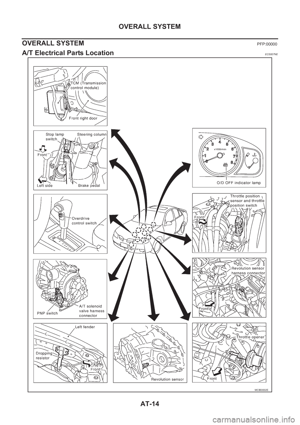
A/T Electrical Parts LocationECS007NE
MCIB0002E
Page 1486 of 3189
AT-30
OVERALL SYSTEM
SHIFT CONTROL
The shift is regulated entirely by electronic control to accommodate vehicle speed and varying engine opera-
tions. This is accomplished by electrical signals transmitted by the revolution sensor and throttle position sen-
sor. This results in improved acceleration performance and fuel economy.
Control of Shift Solenoid Valves A and B
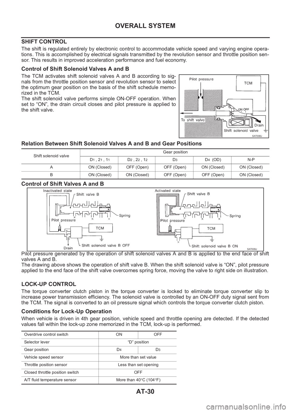
The TCM activates shift solenoid valves A and B according to sig-
nals from the throttle position sensor and revolution sensor to select
the optimum gear position on the basis of the shift schedule memo-
rized in the TCM.
The shift solenoid valve performs simple ON-OFF operation. When
set to “ON”, the drain circuit closes and pilot pressure is applied to
the shift valve.
Relation Between Shift Solenoid Valves A and B and Gear Positions
Control of Shift Valves A and B
Pilot pressure generated by the operation of shift solenoid valves A and B is applied to the end face of shift
valves A and B.
The drawing above shows the operation of shift valve B. When the shift solenoid valve is “ON”, pilot pressure
applied to the end face of the shift valve overcomes spring force, moving the valve to right side on illustration.
LOCK-UP CONTROL
The torque converter clutch piston in the torque converter is locked to eliminate torque converter slip to
increase power transmission efficiency. The solenoid valve is controlled by an ON-OFF duty signal sent from
the TCM. The signal is converted to an oil pressure signal which controls the torque converter clutch piston.
Conditions for Lock-Up Operation
When vehicle is driven in 4th gear position, vehicle speed and throttle opening are detected. If the detected
values fall within the lock-up zone memorized in the TCM, lock-up is performed.
SAT008J
Shift solenoid valveGear position
D1 , 21 , 11D2 , 22 , 12D3D4 (OD) N-P
A ON (Closed) OFF (Open) OFF (Open) ON (Closed) ON (Closed)
B ON (Closed) ON (Closed) OFF (Open) OFF (Open) ON (Closed)
SAT009J
Overdrive control switch ON OFF
Selector lever “D” position
Gear position D
4D3
Vehicle speed sensor More than set value
Throttle position sensor Less than set opening
Closed throttle position switch OFF
A/T fluid temperature sensor More than 40°C (104°F)