2003 NISSAN ALMERA N16 Electric
[x] Cancel search: ElectricPage 2231 of 3189
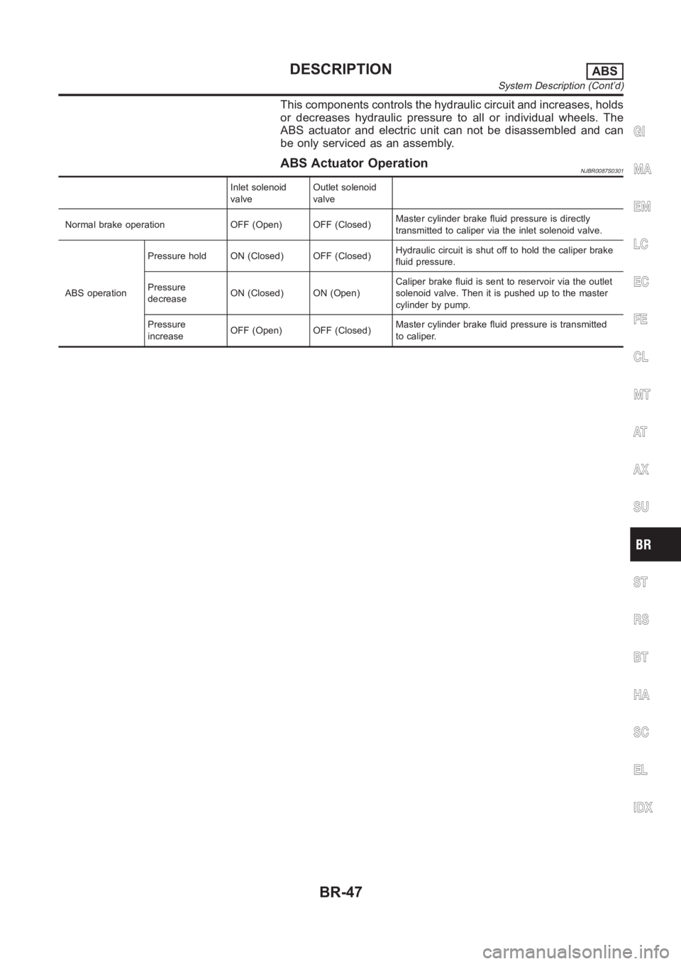
This components controls the hydraulic circuit and increases, holds
or decreases hydraulic pressure to all or individual wheels. The
ABS actuator and electric unit can not be disassembled and can
be only serviced as an assembly.
ABS Actuator OperationNJBR0087S0301
Inlet solenoid
valveOutlet solenoid
valve
Normal brake operation OFF (Open) OFF (Closed)Master cylinder brake fluid pressure is directly
transmitted to caliper via the inlet solenoid valve.
ABS operationPressure hold ON (Closed) OFF (Closed)Hydraulic circuit is shut off to hold the caliper brake
fluid pressure.
Pressure
decreaseON (Closed) ON (Open)Caliper brake fluid is sent to reservoir via the outlet
solenoid valve. Then it is pushed up to the master
cylinder by pump.
Pressure
increaseOFF (Open) OFF (Closed)Master cylinder brake fluid pressure is transmitted
to caliper.
GI
MA
EM
LC
EC
FE
CL
MT
AT
AX
SU
ST
RS
BT
HA
SC
EL
IDX
DESCRIPTIONABS
System Description (Cont’d)
BR-47
Page 2238 of 3189
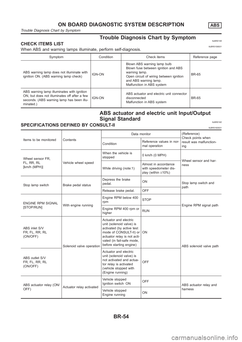
Trouble Diagnosis Chart by SymptomNJBR0159CHECK ITEMS LISTNJBR0159S01When ABS and warning lamps illuminate, perform self-diagnosis.
Symptom Condition Check items Reference page
ABS warning lamp does not illuminate with
ignition ON. (ABS warning lamp check)IGN-ONBlown ABS warning lamp bulb
Blown fuse between ignition and ABS
warning lamp.
Open circuit of wiring between ignition
and ABS warning lamp.
Malfunction in ABS systemBR-65
ABS warning lamp illuminates with ignition
ON, but does not illuminates off after a few
seconds. (ABS warning lamp has been illu-
minated.)IGN-ONABS actuator and electric unit connector
disconnected
Malfunction in ABS systemBR-65
ABS actuator and electric unit Input/Output
Signal Standard
NJBR0160SPECIFICATIONS DEFINED BY CONSULT-IINJBR0160S01
Items to be monitored ContentsData monitor(Reference)
Check points when
result was malfunction-
ing ConditionReference values in nor-
mal operation
Wheel sensor FR,
FL, RR, RL
[km/h (MPH)]Vehicle wheel speedWhen the vehicle is
stopped0 km/h (0 MPH)
Wheel sensor and har-
ness
While driving (note:1)Almost in accordance
with speedometer dis-
play (within±10%)
Stop lamp switch Brake pedal statusDepress the brake
pedal.ON
Stop lamp switch and
path
Release brake pedal. OFF
ENGINE RPM SIGNAL
[STOP/RUN]With engine runningEngine RPM below 400
rpmSTOP
Engine RPM signal path
Engine RPM 400 rpm or
higherRUN
ABS inlet S/V
FR, FL, RR, RL
(ON/OFF)
Solenoid valve operationActuator and electric
unit (solenoid valve) is
activated (by active test
mode of CONSULT-II) or
actuator relay is not acti-
vated (in fail-safe mode,
before starting engine)ON
ABS solenoid valve path
ABS outlet S/V
FR, FL, RR, RL
(ON/OFF)Actuator and electric
unit (solenoid valve) is
not activated and actua-
tor relay is activated
(vehicle stopped with
(Engine running)OFF
ABS actuator relay (ON/
OFF)Actuator relay activatedVehicle stopped
Ignition switch ONOFF
ABS actuator relay and
harness
Vehicle stopped
Engine runningON
ON BOARD DIAGNOSTIC SYSTEM DESCRIPTIONABS
Trouble Diagnosis Chart by Symptom
BR-54
Page 2239 of 3189
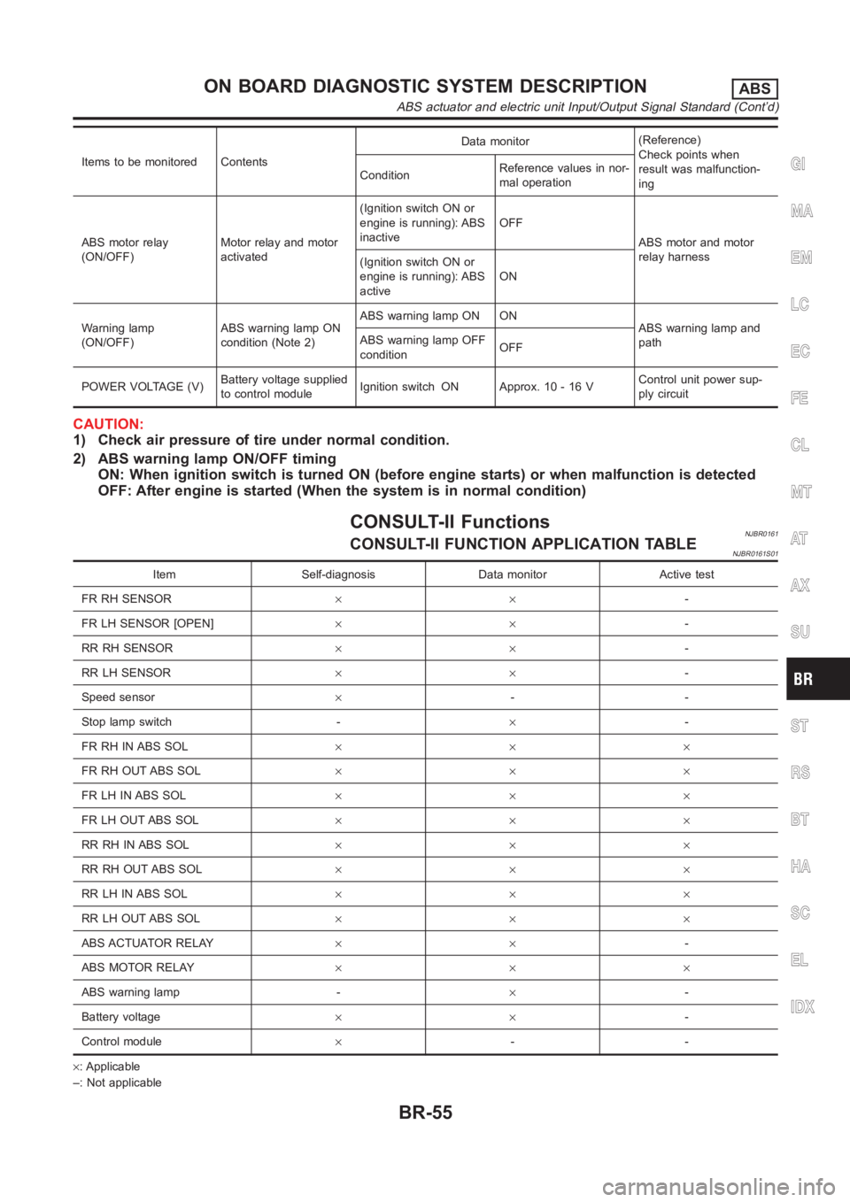
Items to be monitored ContentsData monitor(Reference)
Check points when
result was malfunction-
ing ConditionReference values in nor-
mal operation
ABS motor relay
(ON/OFF)Motor relay and motor
activated(Ignition switch ON or
engine is running): ABS
inactiveOFF
ABS motor and motor
relay harness
(Ignition switch ON or
engine is running): ABS
activeON
Warning lamp
(ON/OFF)ABS warning lamp ON
condition (Note 2)ABS warning lamp ON ON
ABS warning lamp and
path ABS warning lamp OFF
conditionOFF
POWER VOLTAGE (V)Battery voltage supplied
to control moduleIgnition switch ON Approx. 10 - 16 VControl unit power sup-
ply circuit
CAUTION:
1) Check air pressure of tire under normal condition.
2) ABS warning lamp ON/OFF timing
ON: When ignition switch is turned ON (before engine starts) or when malfunction is detected
OFF: After engine is started (When the system is in normal condition)
CONSULT-II FunctionsNJBR0161CONSULT-II FUNCTION APPLICATION TABLENJBR0161S01
Item Self-diagnosis Data monitor Active test
FR RH SENSOR××-
FR LH SENSOR [OPEN]××-
RR RH SENSOR××-
RR LH SENSOR××-
Speed sensor×--
Stop lamp switch -×-
FR RH IN ABS SOL×××
FR RH OUT ABS SOL×××
FR LH IN ABS SOL×××
FR LH OUT ABS SOL×××
RR RH IN ABS SOL×××
RR RH OUT ABS SOL×××
RR LH IN ABS SOL×××
RR LH OUT ABS SOL×××
ABS ACTUATOR RELAY××-
ABS MOTOR RELAY×××
ABS warning lamp -×-
Battery voltage××-
Control module×--
×: Applicable
–: Not applicable
GI
MA
EM
LC
EC
FE
CL
MT
AT
AX
SU
ST
RS
BT
HA
SC
EL
IDX
ON BOARD DIAGNOSTIC SYSTEM DESCRIPTIONABS
ABS actuator and electric unit Input/Output Signal Standard (Cont’d)
BR-55
Page 2242 of 3189
![NISSAN ALMERA N16 2003 Electronic Repair Manual Faulty lines Malfunction detecting condition Check harness
RR RH OUT ABS SOL
[OPEN] [SHORT]At RH rear wheel ABS outlet solenoid valve, following
conditions occur: open circuit, output voltage is abnor NISSAN ALMERA N16 2003 Electronic Repair Manual Faulty lines Malfunction detecting condition Check harness
RR RH OUT ABS SOL
[OPEN] [SHORT]At RH rear wheel ABS outlet solenoid valve, following
conditions occur: open circuit, output voltage is abnor](/manual-img/5/57350/w960_57350-2241.png)
Faulty lines Malfunction detecting condition Check harness
RR RH OUT ABS SOL
[OPEN] [SHORT]At RH rear wheel ABS outlet solenoid valve, following
conditions occur: open circuit, output voltage is abnor-
mally lower or higher than control value by short to
ground on control line.
ABS solenoid valve and actua-
tor relay harness
RR LH OUT ABS SOL
[OPEN] [SHORT]At LH rear wheel ABS outlet solenoid valve, following
conditions occur: open circuit, output voltage is abnor-
mally lower or higher than control value by short to
ground on control line.
ABS motor [ON error]ABS actuator motor turned ON when the ABS motor is
controlled OFF.
ABS motor relay and harness
ABS motor [OFF error]ABS actuator motor turned OFF when the ABS motor is
controlled ON.
ABS actuator relay [ON error] ABS actuator relay turned ON wheel it is controlled OFF.
ABS actuator relay and har-
ness ABS ACTUATOR RELAY
[OFF abnormal]ABS actuator relay turned OFF wheel it is controlled ON.
BATTERY VOLTAGE [ABNORMAL]Power source voltage supplied to ABS actuator and elec-
tric unit is abnormally low.ABS actuator and electric unit
power supply circuit
CONTROL UNITFunction of calculation in ABS actuator and electric unit
has failed.ABS actuator and electric unit,
power and ground circuits
(Note 1): When vehicle was stuck on slippery road, and spin its wheels for Approx. 10 - 80 seconds (the period depends on vehicle
speed). ABS warning lamp may come on. However, this is not abnormal.
(Note 2): Repair short circuit in sensor. ABS warning lamp will come on whenignition switch is turned ON. According to self-diagnosis
operation procedure, drive vehicle at Approx. 30 km/h (19 MPH). Then checkABS warning lamp goes out in about one minute.
DATA MONITORNJBR0161S03For details of data monitor function, refer to CONSULT-II
Instruction Manual.
Operation ProcedureNJBR0161S03011. Turn the ignition switch to OFF.
2. Connect CONSULT-II connector to data link connector on
vehicle.
3. Turn ignition switch ON.
MBIB0233E
4. Touch “START (NISSAN BASED VHCL)” on the display.
ON BOARD DIAGNOSTIC SYSTEM DESCRIPTIONABS
CONSULT-II Functions (Cont’d)
BR-58
Page 2244 of 3189
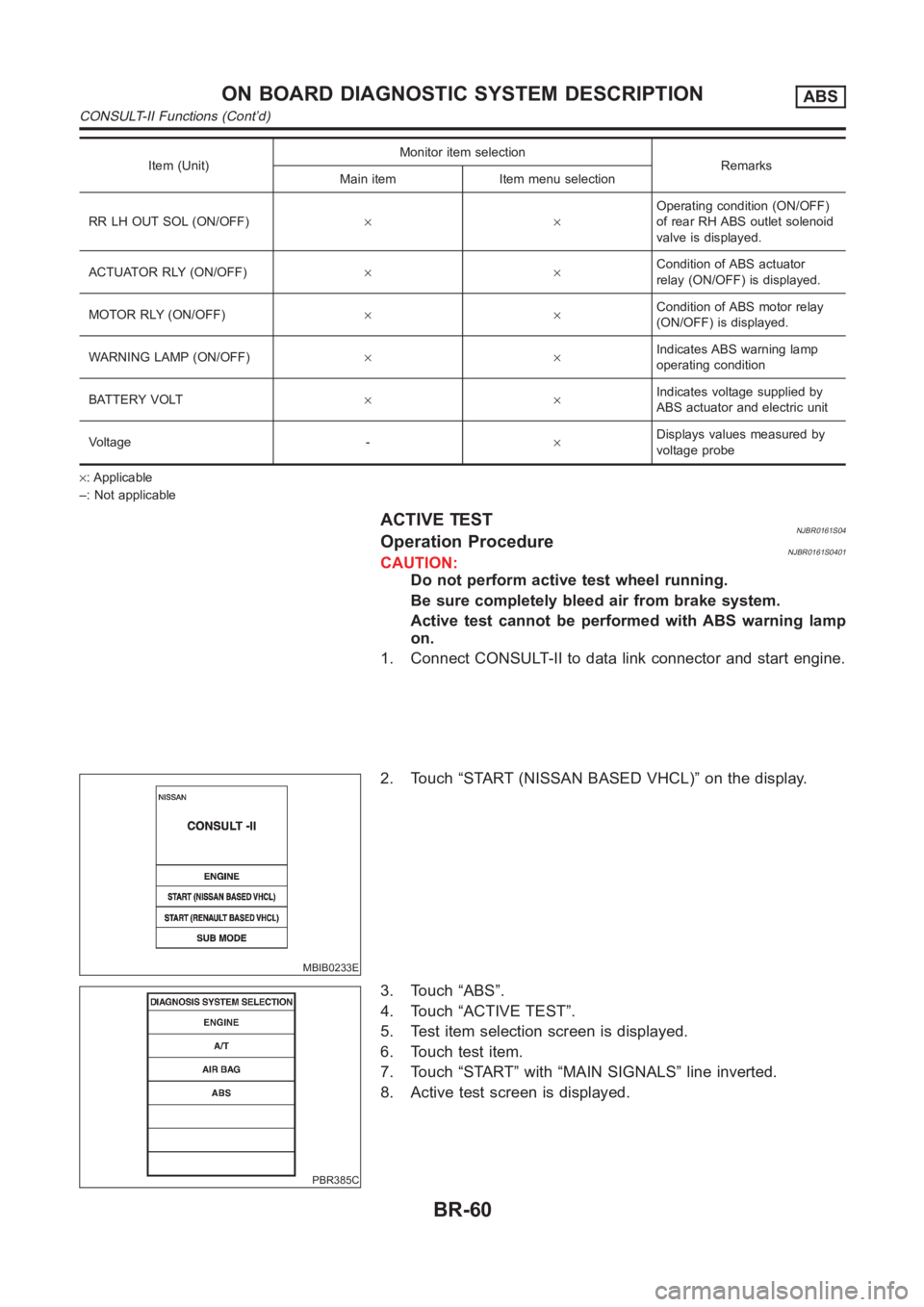
Item (Unit)Monitor item selection
Remarks
Main item Item menu selection
RR LH OUT SOL (ON/OFF)××Operating condition (ON/OFF)
of rear RH ABS outlet solenoid
valve is displayed.
ACTUATOR RLY (ON/OFF)××Condition of ABS actuator
relay (ON/OFF) is displayed.
MOTOR RLY (ON/OFF)××Condition of ABS motor relay
(ON/OFF) is displayed.
WARNING LAMP (ON/OFF)××Indicates ABS warning lamp
operating condition
BATTERY VOLT××Indicates voltage supplied by
ABS actuator and electric unit
Voltage -×Displays values measured by
voltage probe
×: Applicable
–: Not applicable
ACTIVE TESTNJBR0161S04Operation ProcedureNJBR0161S0401CAUTION:
Do not perform active test wheel running.
Be sure completely bleed air from brake system.
Active test cannot be performed with ABS warning lamp
on.
1. Connect CONSULT-II to data link connector and start engine.
MBIB0233E
2. Touch “START (NISSAN BASED VHCL)” on the display.
PBR385C
3. Touch “ABS”.
4. Touch “ACTIVE TEST”.
5. Test item selection screen is displayed.
6. Touch test item.
7. Touch “START” with “MAIN SIGNALS” line inverted.
8. Active test screen is displayed.
ON BOARD DIAGNOSTIC SYSTEM DESCRIPTIONABS
CONSULT-II Functions (Cont’d)
BR-60
Page 2246 of 3189
YBR319
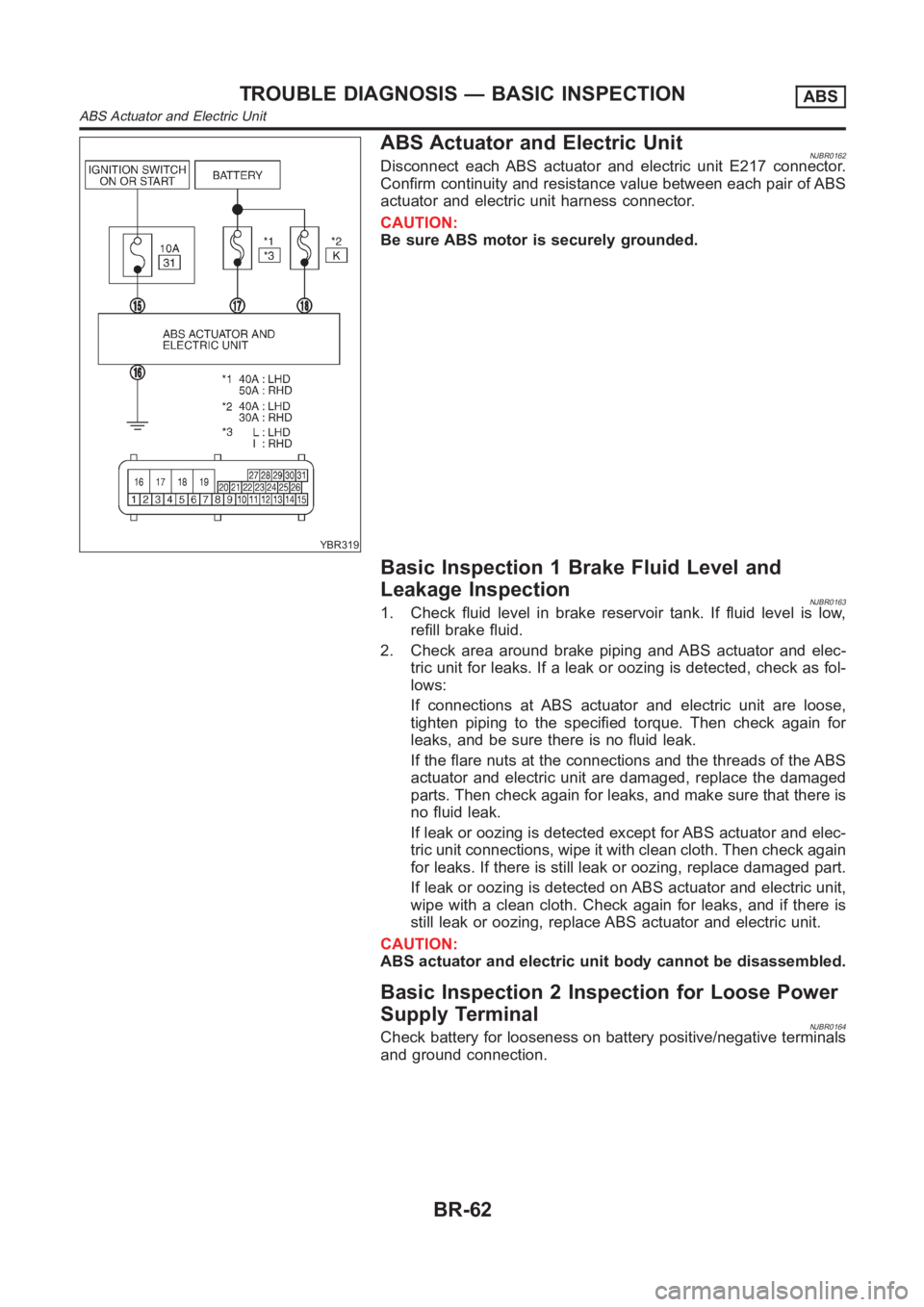
ABS Actuator and Electric UnitNJBR0162Disconnect each ABS actuator and electric unit E217 connector.
Confirm continuity and resistance value between each pair of ABS
actuator and electric unit harness connector.
CAUTION:
Be sure ABS motor is securely grounded.
Basic Inspection 1 Brake Fluid Level and
Leakage Inspection
NJBR01631. Check fluid level in brake reservoir tank. If fluid level is low,
refill brake fluid.
2. Check area around brake piping and ABS actuator and elec-
tric unit for leaks. If a leak or oozing is detected, check as fol-
lows:
If connections at ABS actuator and electric unit are loose,
tighten piping to the specified torque. Then check again for
leaks, and be sure there is no fluid leak.
If the flare nuts at the connections and the threads of the ABS
actuator and electric unit are damaged, replace the damaged
parts. Then check again for leaks, and make sure that there is
no fluid leak.
If leak or oozing is detected except for ABS actuator and elec-
tric unit connections, wipe it with clean cloth. Then check again
for leaks. If there is still leak or oozing, replace damaged part.
If leak or oozing is detected on ABS actuator and electric unit,
wipe with a clean cloth. Check again for leaks, and if there is
still leak or oozing, replace ABS actuator and electric unit.
CAUTION:
ABS actuator and electric unit body cannot be disassembled.
Basic Inspection 2 Inspection for Loose Power
Supply Terminal
NJBR0164Check battery for looseness on battery positive/negative terminals
and ground connection.
TROUBLE DIAGNOSIS — BASIC INSPECTIONABS
ABS Actuator and Electric Unit
BR-62
Page 2248 of 3189
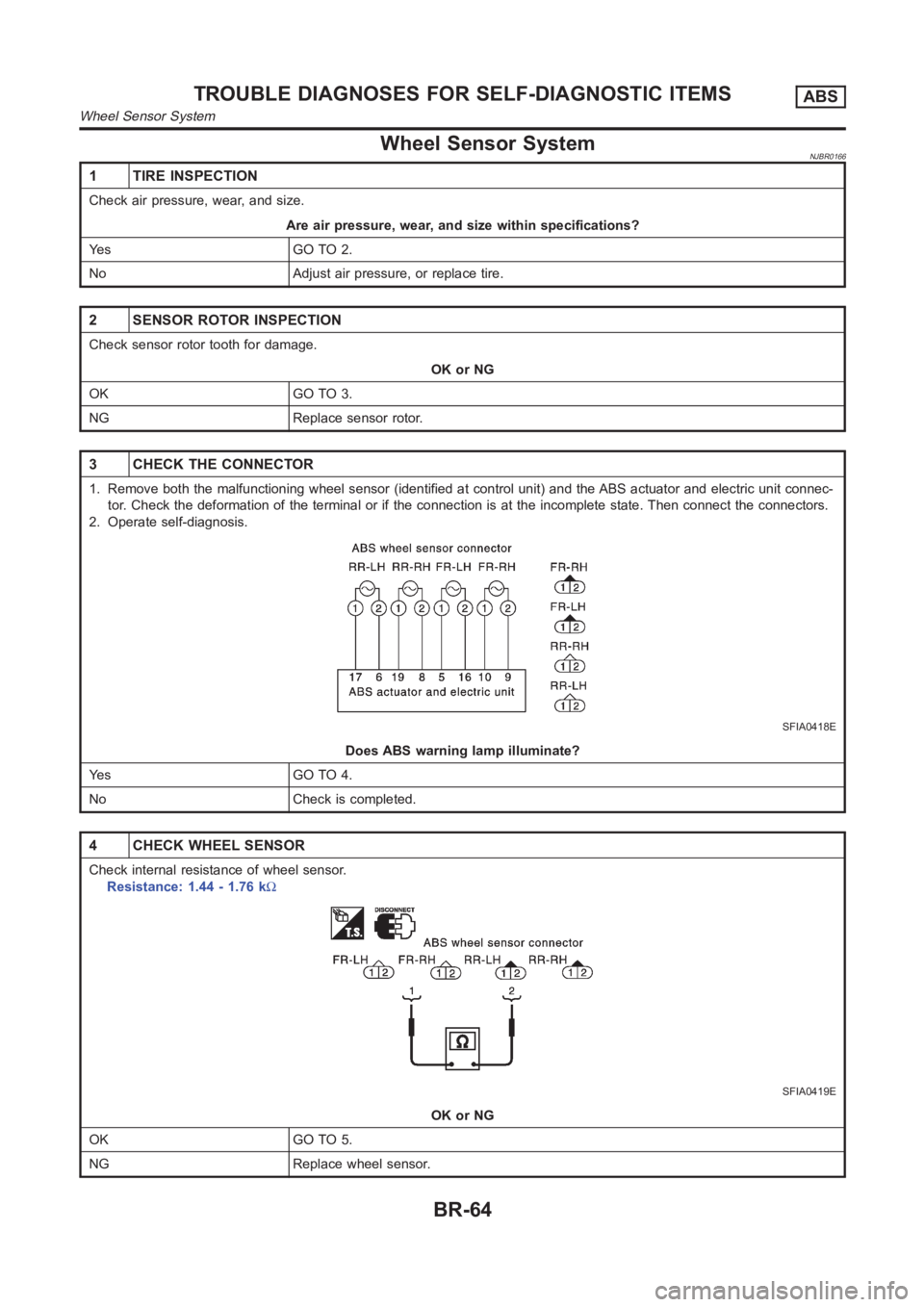
Wheel Sensor SystemNJBR0166
1 TIRE INSPECTION
Check air pressure, wear, and size.
Are air pressure, wear, and size within specifications?
Ye s G O T O 2 .
No Adjust air pressure, or replace tire.
2 SENSOR ROTOR INSPECTION
Check sensor rotor tooth for damage.
OK or NG
OK GO TO 3.
NG Replace sensor rotor.
3 CHECK THE CONNECTOR
1. Remove both the malfunctioning wheel sensor (identified at control unit) and the ABS actuator and electric unit connec-
tor. Check the deformation of the terminal or if the connection is at the incomplete state. Then connect the connectors.
2. Operate self-diagnosis.
SFIA0418E
Does ABS warning lamp illuminate?
Ye s G O T O 4 .
No Check is completed.
4 CHECK WHEEL SENSOR
Check internal resistance of wheel sensor.
Resistance: 1.44 - 1.76 kΩ
SFIA0419E
OK or NG
OK GO TO 5.
NG Replace wheel sensor.
TROUBLE DIAGNOSES FOR SELF-DIAGNOSTIC ITEMSABS
Wheel Sensor System
BR-64
Page 2249 of 3189
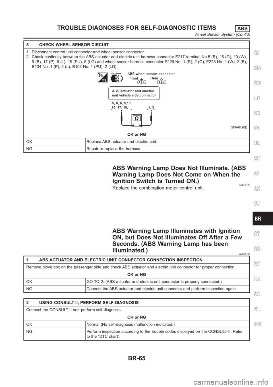
5 CHECK WHEEL SENSOR CIRCUIT
1. Disconnect control unit connector and wheel sensor connector.
2. Check continuity between the ABS actuator and electric unit harness connector E217 terminal No.5 (R), 16 (G), 10 (W),
9 (B), 17 (P), 6 (L), 19 (PU), 8 (LG) and wheel sensor harness connector E226 No. 1 (R), 2 (G), E228 No .1 (W), 2 (B),
B104 No .1 (P), 2 (L), B103 No. 1 (PU), 2 (LG)
SFIA0420E
OK or NG
OK Replace ABS actuator and electric unit.
NG Repair or replace the harness.
ABS Warning Lamp Does Not Illuminate. (ABS
Warning Lamp Does Not Come on When the
Ignition Switch is Turned ON.)
NJBR0167Replace the combination meter control unit.
ABS Warning Lamp Illuminates with Ignition
ON, but Does Not Illuminates Off After a Few
Seconds. (ABS Warning Lamp has been
Illuminated.)
NJBR0168
1 ABS ACTUATOR AND ELECTRIC UNIT CONNECTOR CONNECTION INSPECTION
Remove glove box on the passenger side and check ABS actuator and electric unit connector for proper connection.
OK or NG
OK GO TO 2. (ABS actuator and electric unit connector is properly connected.)
NG Connect the ABS actuator and electric unit connector and perform inspection again.
2 USING CONSULT-II, PERFORM SELF-DIAGNOSIS
Connect the CONSULT-II and perform self-diagnosis.
OK or NG
OK Normal (No self-diagnosis malfunction indicated.)
NG Perform inspection according to the trouble codes displayed on the CONSULT-II. Refer
to the “DTC chart”.
GI
MA
EM
LC
EC
FE
CL
MT
AT
AX
SU
ST
RS
BT
HA
SC
EL
IDX
TROUBLE DIAGNOSES FOR SELF-DIAGNOSTIC ITEMSABS
Wheel Sensor System (Cont’d)
BR-65