Page 2530 of 3189
SPEED DEPENDENT VOLUME CONTROLNJEL0497S13DescriptionNJEL0497S1301If activated, the radio output volume will be automatically adjusted to compensate for increased driving noises
at higher driving speeds.
The radio receives a speed signal from the combination meter and selects the output volume.
PERSONAL AUDIO SETTINGSNJEL0497S14DescriptionNJEL0497S1401The radio is designed to store several settings (volume, bass, treble, preset stations and level of speed
dependent volume control) with every NATS ignition key used. Up to a maximum of 4 NATS keys can be reg-
istered. During the communication mentioned under “Anti-Theft System”,the radio will recognize the used
ignition key and select the accompanying settings.
Component Parts LocationNJEL0554EL-543, “ELECTRIC UNIT LOCATION”.
AUDIO
System Description (Cont’d)
EL-194
Page 2553 of 3189

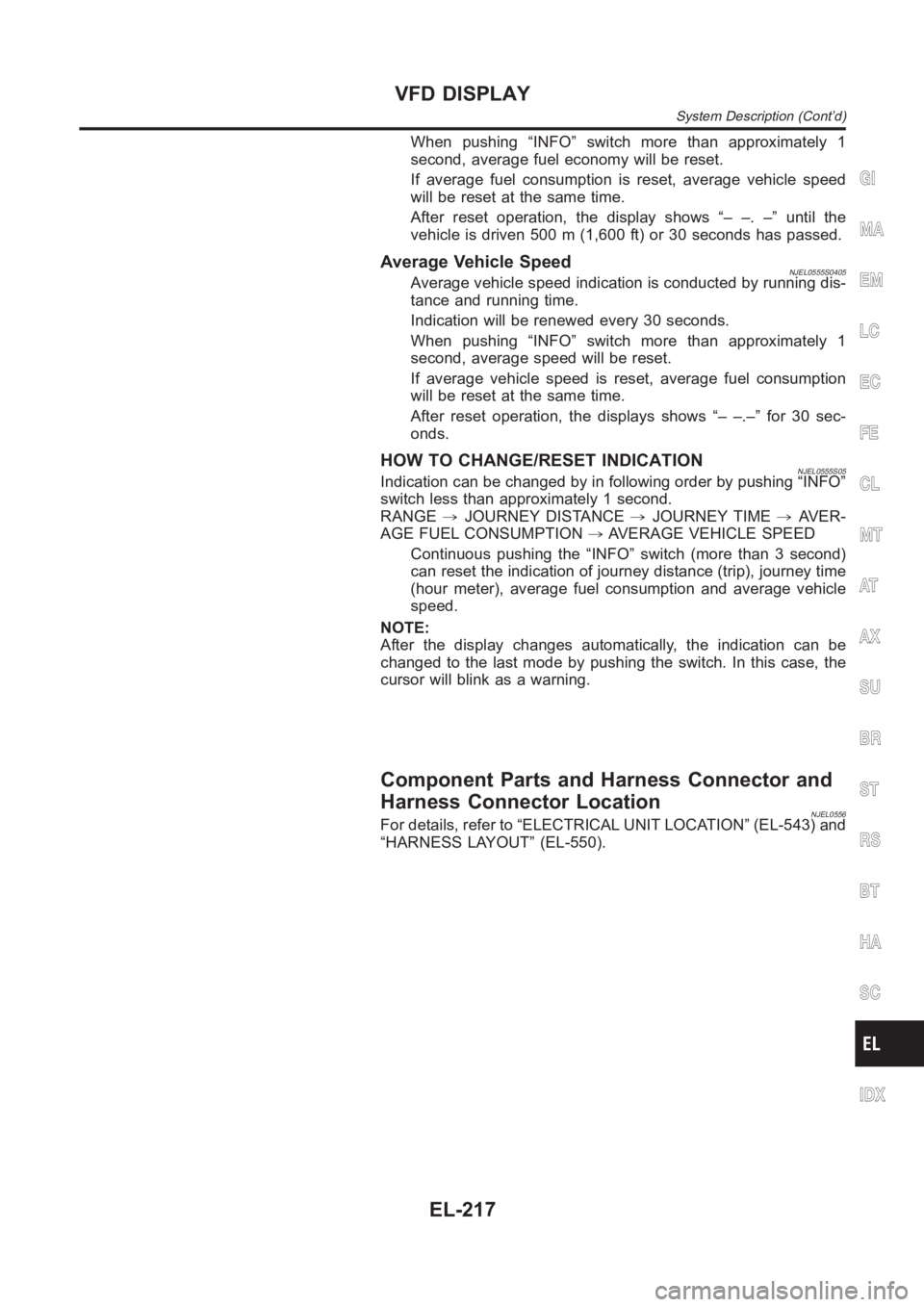
When pushing “INFO” switch more than approximately 1
second, average fuel economy will be reset.
If average fuel consumption is reset, average vehicle speed
will be reset at the same time.
After reset operation, the display shows “– –. –” until the
vehicle is driven 500 m (1,600 ft) or 30 seconds has passed.
Average Vehicle SpeedNJEL0555S0405Average vehicle speed indication is conducted by running dis-
tance and running time.
Indication will be renewed every 30 seconds.
When pushing “INFO” switch more than approximately 1
second, average speed will be reset.
If average vehicle speed is reset, average fuel consumption
will be reset at the same time.
After reset operation, the displays shows “– –.–” for 30 sec-
onds.
HOW TO CHANGE/RESET INDICATIONNJEL0555S05Indication can be changed by in following order by pushing “INFO”
switch less than approximately 1 second.
RANGE,JOURNEY DISTANCE,JOURNEY TIME,AVER-
AGE FUEL CONSUMPTION,AVERAGE VEHICLE SPEED
Continuous pushing the “INFO” switch (more than 3 second)
can reset the indication of journey distance (trip), journey time
(hour meter), average fuel consumption and average vehicle
speed.
NOTE:
After the display changes automatically, the indication can be
changed to the last mode by pushing the switch. In this case, the
cursor will blink as a warning.
Component Parts and Harness Connector and
Harness Connector Location
NJEL0556For details, refer to “ELECTRICAL UNIT LOCATION” (EL-543) and
“HARNESS LAYOUT” (EL-550).
GI
MA
EM
LC
EC
FE
CL
MT
AT
AX
SU
BR
ST
RS
BT
HA
SC
IDX
VFD DISPLAY
System Description (Cont’d)
EL-217
Page 2578 of 3189
![NISSAN ALMERA N16 2003 Electronic Repair Manual Warning indicatorsWarning lamps in
instrument panelWarning detection and cancel conditions Cases of malfunction
DOOR OPEN DoorDetection conditionVehicle is running [approx. 5
km/h (3 MPH) or faster] a NISSAN ALMERA N16 2003 Electronic Repair Manual Warning indicatorsWarning lamps in
instrument panelWarning detection and cancel conditions Cases of malfunction
DOOR OPEN DoorDetection conditionVehicle is running [approx. 5
km/h (3 MPH) or faster] a](/manual-img/5/57350/w960_57350-2577.png)
Warning indicatorsWarning lamps in
instrument panelWarning detection and cancel conditions Cases of malfunction
DOOR OPEN DoorDetection conditionVehicle is running [approx. 5
km/h (3 MPH) or faster] and door
ajar of any of the doors is
detected.Doorisopen
Cancel conditionVehicle is stopped and all the
doors lock.
ABS ABSDetection conditionWarning lamp ON signal is
detected when engine is running.
ABS control system mal-
function
Cancel conditionWarning lamp OFF signal is
detected.
ESP ELECTRONIC
CONTROL SYSTEMESPDetection conditionWarning lamp ON signal is
detected when engine is running.
ESP system malfunction
Cancel conditionWarning lamp OFF signal is
detected.
CVT ELECTRONIC
CONTROL SYSTEMCVTDetection conditionWarning lamp ON signal is
detected after ignition switch is
turned ON.
TCM system malfunction
Cancel conditionWarning lamp OFF signal is
detected.
CRUISE CONTROL
SYSTEMCRUISEDetection conditionWarning lamp ON signal is
detected after ignition switch is
turned ON.
ICC system malfunction
Cancel conditionWarning lamp OFF signal is
detected.
Precautions for Display Unit ReplacementNJEL0572Record the following memorized contents before replacing the control unit.
Preset frequency
Area for indicating station, selection of overlapped stations
Program status
Volume balance memory set values
Equalizer memory set values
Brightness of light when ON/OFF
Dimming switching
Display color switching
Replace the display unit after disconnecting both battery cables.
Component Parts and Harness Connector and
Harness Connector Location
NJEL0573For details, refer to “ELECTRICAL UNIT LOCATION” (EL-543) and “HARNESS LAYOUT” (EL-550).
LCD DISPLAY
System Description (Cont’d)
EL-242
Page 2704 of 3189

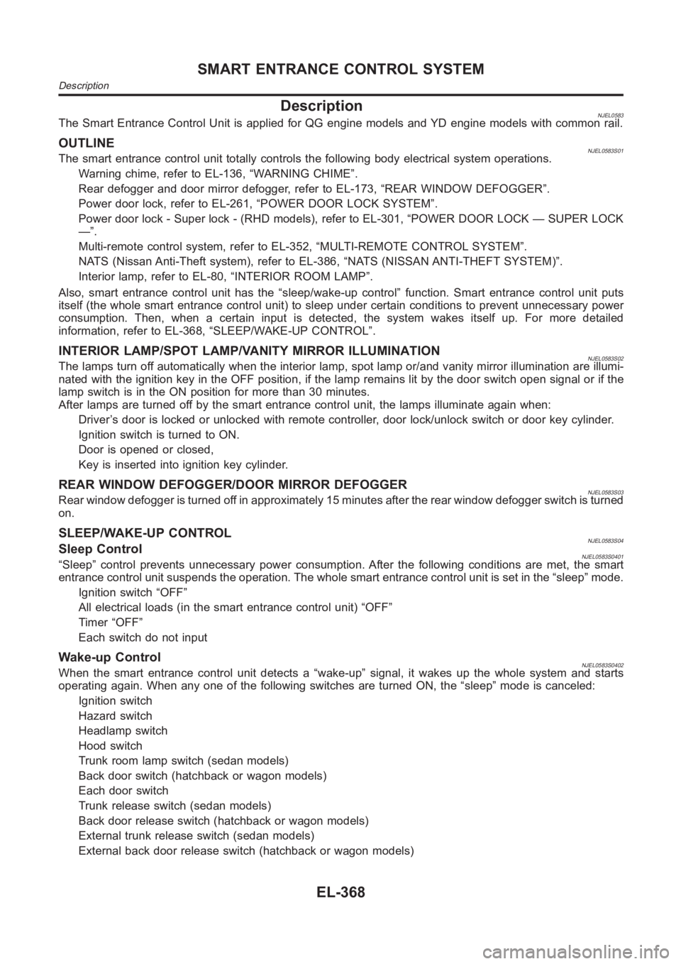
DescriptionNJEL0583The Smart Entrance Control Unit is applied for QG engine models and YD engine models with common rail.
OUTLINENJEL0583S01The smart entrance control unit totally controls the following body electrical system operations.
Warning chime, refer to EL-136, “WARNING CHIME”.
Rear defogger and door mirror defogger, refer to EL-173, “REAR WINDOW DEFOGGER”.
Power door lock, refer to EL-261, “POWER DOOR LOCK SYSTEM”.
Power door lock - Super lock - (RHD models), refer to EL-301, “POWER DOOR LOCK — SUPER LOCK
—”.
Multi-remote control system, refer to EL-352, “MULTI-REMOTE CONTROL SYSTEM”.
NATS (Nissan Anti-Theft system), refer to EL-386, “NATS (NISSAN ANTI-THEFT SYSTEM)”.
Interior lamp, refer to EL-80, “INTERIOR ROOM LAMP”.
Also, smart entrance control unit has the “sleep/wake-up control” function. Smart entrance control unit puts
itself (the whole smart entrance control unit) to sleep under certain conditions to prevent unnecessary power
consumption. Then, when a certain input is detected, the system wakes itself up. For more detailed
information, refer to EL-368, “SLEEP/WAKE-UP CONTROL”.
INTERIOR LAMP/SPOT LAMP/VANITY MIRROR ILLUMINATIONNJEL0583S02The lamps turn off automatically when the interior lamp, spot lamp or/and vanity mirror illumination are illumi-
nated with the ignition key in the OFF position, if the lamp remains lit by the door switch open signal or if the
lamp switch is in the ON position for more than 30 minutes.
After lamps are turned off by the smart entrance control unit, the lamps illuminate again when:
Driver’s door is locked or unlocked with remote controller, door lock/unlock switch or door key cylinder.
Ignition switch is turned to ON.
Door is opened or closed,
Key is inserted into ignition key cylinder.
REAR WINDOW DEFOGGER/DOOR MIRROR DEFOGGERNJEL0583S03Rear window defogger is turned off in approximately 15 minutes after the rear window defogger switch is turned
on.
SLEEP/WAKE-UP CONTROLNJEL0583S04Sleep ControlNJEL0583S0401“Sleep” control prevents unnecessary power consumption. After the following conditions are met, the smart
entrance control unit suspends the operation. The whole smart entrance control unit is set in the “sleep” mode.
Ignition switch “OFF”
All electrical loads (in the smart entrance control unit) “OFF”
Timer “OFF”
Each switch do not input
Wake-up ControlNJEL0583S0402When the smart entrance control unit detects a “wake-up” signal, it wakes up the whole system and starts
operating again. When any one of the following switches are turned ON, the “sleep” mode is canceled:
Ignition switch
Hazard switch
Headlamp switch
Hood switch
Trunk room lamp switch (sedan models)
Back door switch (hatchback or wagon models)
Each door switch
Trunk release switch (sedan models)
Back door release switch (hatchback or wagon models)
External trunk release switch (sedan models)
External back door release switch (hatchback or wagon models)
SMART ENTRANCE CONTROL SYSTEM
Description
EL-368
Page 2722 of 3189

Component Parts and Harness Connetor
Location
NJEL0406For details, refer to “ELECTRICAL UNIT LOCATION” (EL-543) and
“HARNESS LAYOUT” (EL-550).
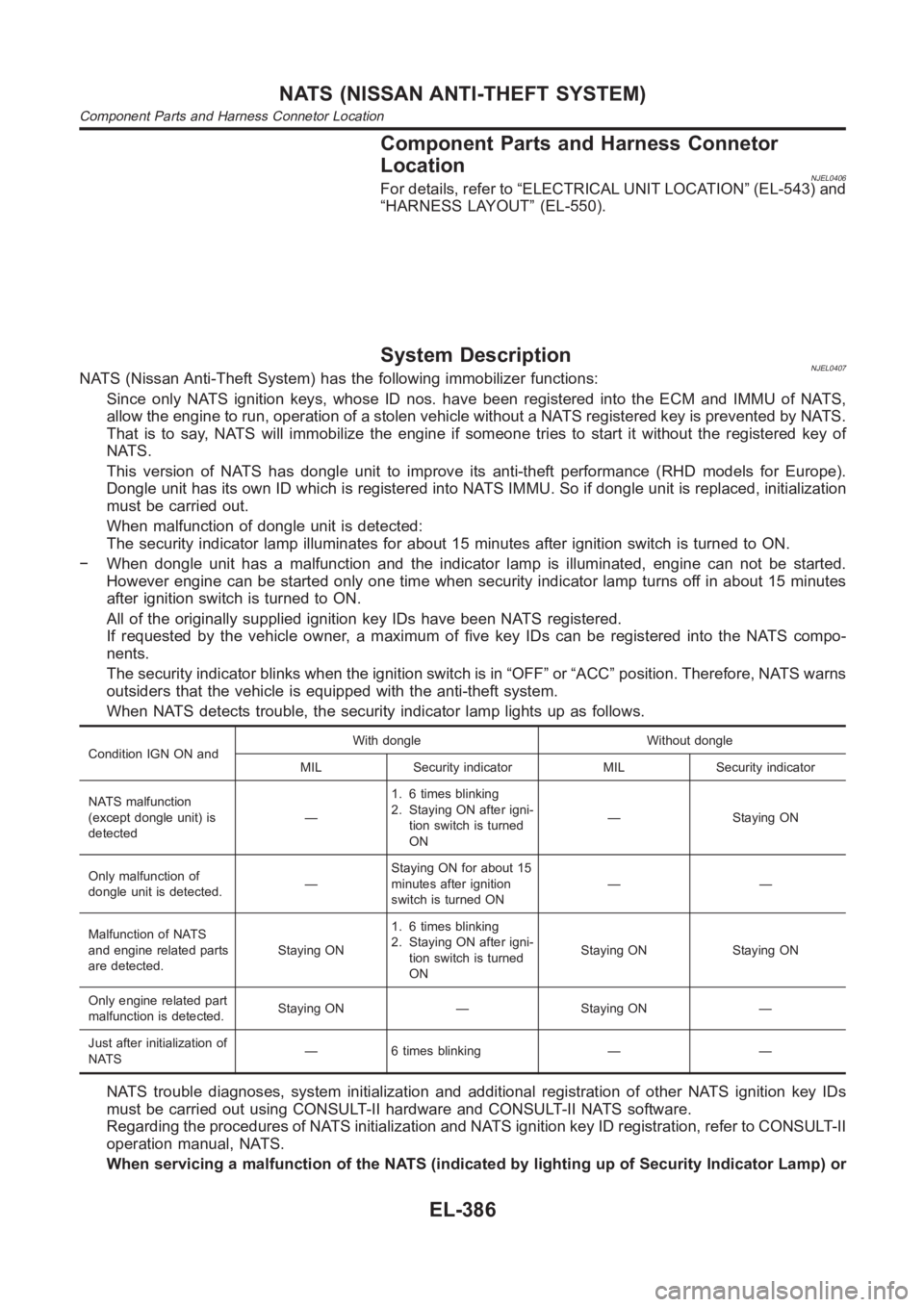
System DescriptionNJEL0407NATS (Nissan Anti-Theft System) has the following immobilizer functions:
Since only NATS ignition keys, whose ID nos. have been registered into the ECM and IMMU of NATS,
allow the engine to run, operation of a stolen vehicle without a NATS registered key is prevented by NATS.
That is to say, NATS will immobilize the engine if someone tries to start it without the registered key of
NATS.
This version of NATS has dongle unit to improve its anti-theft performance(RHD models for Europe).
Dongle unit has its own ID which is registered into NATS IMMU. So if dongle unit is replaced, initialization
must be carried out.
When malfunction of dongle unit is detected:
The security indicator lamp illuminates for about 15 minutes after ignition switch is turned to ON.
− When dongle unit has a malfunction and the indicator lamp is illuminated,engine can not be started.
However engine can be started only one time when security indicator lamp turns off in about 15 minutes
after ignition switch is turned to ON.
All of the originally supplied ignition key IDs have been NATS registered.
If requested by the vehicle owner, a maximum of five key IDs can be registered into the NATS compo-
nents.
The security indicator blinks when the ignition switch is in “OFF” or “ACC”position. Therefore, NATS warns
outsiders that the vehicle is equipped with the anti-theft system.
When NATS detects trouble, the security indicator lamp lights up as follows.
Condition IGN ON andWith dongle Without dongle
MIL Security indicator MIL Security indicator
NATS malfunction
(except dongle unit) is
detected—1. 6 times blinking
2. Staying ON after igni-
tion switch is turned
ON— Staying ON
Only malfunction of
dongle unit is detected.—Staying ON for about 15
minutes after ignition
switch is turned ON——
Malfunction of NATS
and engine related parts
are detected.Staying ON1. 6 times blinking
2. Staying ON after igni-
tion switch is turned
ONStaying ON Staying ON
Only engine related part
malfunction is detected.Staying ON — Staying ON —
Just after initialization of
NATS— 6 times blinking — —
NATS trouble diagnoses, system initialization and additional registration of other NATS ignition key IDs
must be carried out using CONSULT-II hardware and CONSULT-II NATS software.
Regarding the procedures of NATS initialization and NATS ignition key ID registration, refer to CONSULT-II
operation manual, NATS.
When servicing a malfunction of the NATS (indicated by lighting up of Security Indicator Lamp) or
NATS (NISSAN ANTI-THEFT SYSTEM)
Component Parts and Harness Connetor Location
EL-386
Page 2777 of 3189
Latest status (map screen/bird view , reduced scale, rota-
tion angle of map screen, route guide ON/OFF, track
ON/OFF, etc.)
Current position
Destination, passing point 1 - 5
Registered places, their names, etc.
NOTE:
Only removing the battery does not erase the memory.
Component Parts LocationNJEL0594For details, refer to “ELECTRICAL UNIT LOCATION” (EL-543) and
“HARNESS LAYOUT” (EL-550).
Location of AntennaNJEL0595Refer to EL-214, “Location of Antenna”.
GI
MA
EM
LC
EC
FE
CL
MT
AT
AX
SU
BR
ST
RS
BT
HA
SC
IDX
NAVIGATION SYSTEM
Precautions for AV and NAVI Control Unit Replacement (Cont’d)
EL-441
Page 2879 of 3189
Engine CompartmentNJEL0129
YEL609D
GI
MA
EM
LC
EC
FE
CL
MT
AT
AX
SU
BR
ST
RS
BT
HA
SC
IDX
ELECTRICAL UNITS LOCATION
Engine Compartment
EL-543
Page 2880 of 3189
YEL610D
ELECTRICAL UNITS LOCATION
Engine Compartment (Cont’d)
EL-544