Page 2342 of 3189
PKIA0307E
Do not perform bypass wire connections for the repair parts.
(The spliced wire will become separated and the characteris-
tics of twisted line will be lost.)
Wiring Diagrams and Trouble DiagnosisNJEL0002When you read wiring diagrams, refer to the following:
Refer to GI-12, “HOW TO READ WIRING DIAGRAMS”
Refer to EL-12, “POWER SUPPLY ROUTING” for power distribution circuit
When you perform trouble diagnosis, refer to the following:
Refer to GI-33, “HOW TO FOLLOW TEST GROUPS IN TROUBLE DIAGNOSES”
Refer to GI-22, “HOW TO PERFORM EFFICIENT DIAGNOSIS FOR AN ELECTRICAL INCIDENT”
Check for any Service bulletins before servicing the vehicle.
PRECAUTIONS
Precautions for Harness Repair (Cont’d)
EL-6
Page 2359 of 3189
CEL083
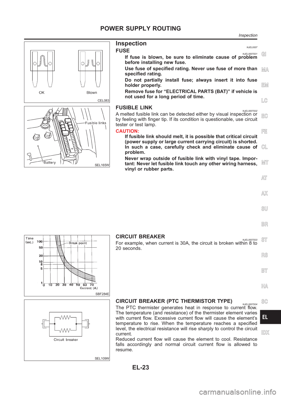
InspectionNJEL0007FUSENJEL0007S01If fuse is blown, be sure to eliminate cause of problem
before installing new fuse.
Use fuse of specified rating. Never use fuse of more than
specified rating.
Do not partially install fuse; always insert it into fuse
holder properly.
Remove fuse for “ELECTRICAL PARTS (BAT)” if vehicle is
not used for a long period of time.
SEL165W
FUSIBLE LINKNJEL0007S02A melted fusible link can be detected either by visual inspection or
by feeling with finger tip. If its condition is questionable, use circuit
tester or test lamp.
CAUTION:
If fusible link should melt, it is possible that critical circuit
(power supply or large current carrying circuit) is shorted.
In such a case, carefully check and eliminate cause of
problem.
Never wrap outside of fusible link with vinyl tape. Impor-
tant: Never let fusible link touch any other wiring harness,
vinyl or rubber parts.
SBF284E
CIRCUIT BREAKERNJEL0007S03For example, when current is 30A, the circuit is broken within 8 to
20 seconds.
SEL109W
CIRCUIT BREAKER (PTC THERMISTOR TYPE)NJEL0007S04The PTC thermister generates heat in response to current flow.
The temperature (and resistance) of the thermister element varies
with current flow. Excessive current flow will cause the element’s
temperature to rise. When the temperature reaches a specified
level, the electrical resistance will rise sharply to control the circuit
current.
Reduced current flow will cause the element to cool. Resistance
falls accordingly and normal circuit current flow is allowed to
resume.
GI
MA
EM
LC
EC
FE
CL
MT
AT
AX
SU
BR
ST
RS
BT
HA
SC
IDX
POWER SUPPLY ROUTING
Inspection
EL-23
Page 2446 of 3189
Component Parts and Harness Connector
Location
NJEL0441For details, refer to “ELECTRICAL UNIT LOCATION” (EL-543) and
“HARNESS LAYOUT” (EL-550).
System DescriptionNJEL0442UNIFIED CONTROL METERNJEL0442S01Speedometer, odo/trip meter, tachometer, fuel gauge and water temperature gauge are controlled totally
by control unit built-in combination meter.
Digital meter is adopted for odo/trip meter.*
*The record of the odo meter is kept even if the battery cable is disconnected. The record of the trip meter
is erased when the battery cable is disconnected.
Odo/trip meter segment can be checked in diagnosis mode.
Meter/gauge can be checked in diagnosis mode.
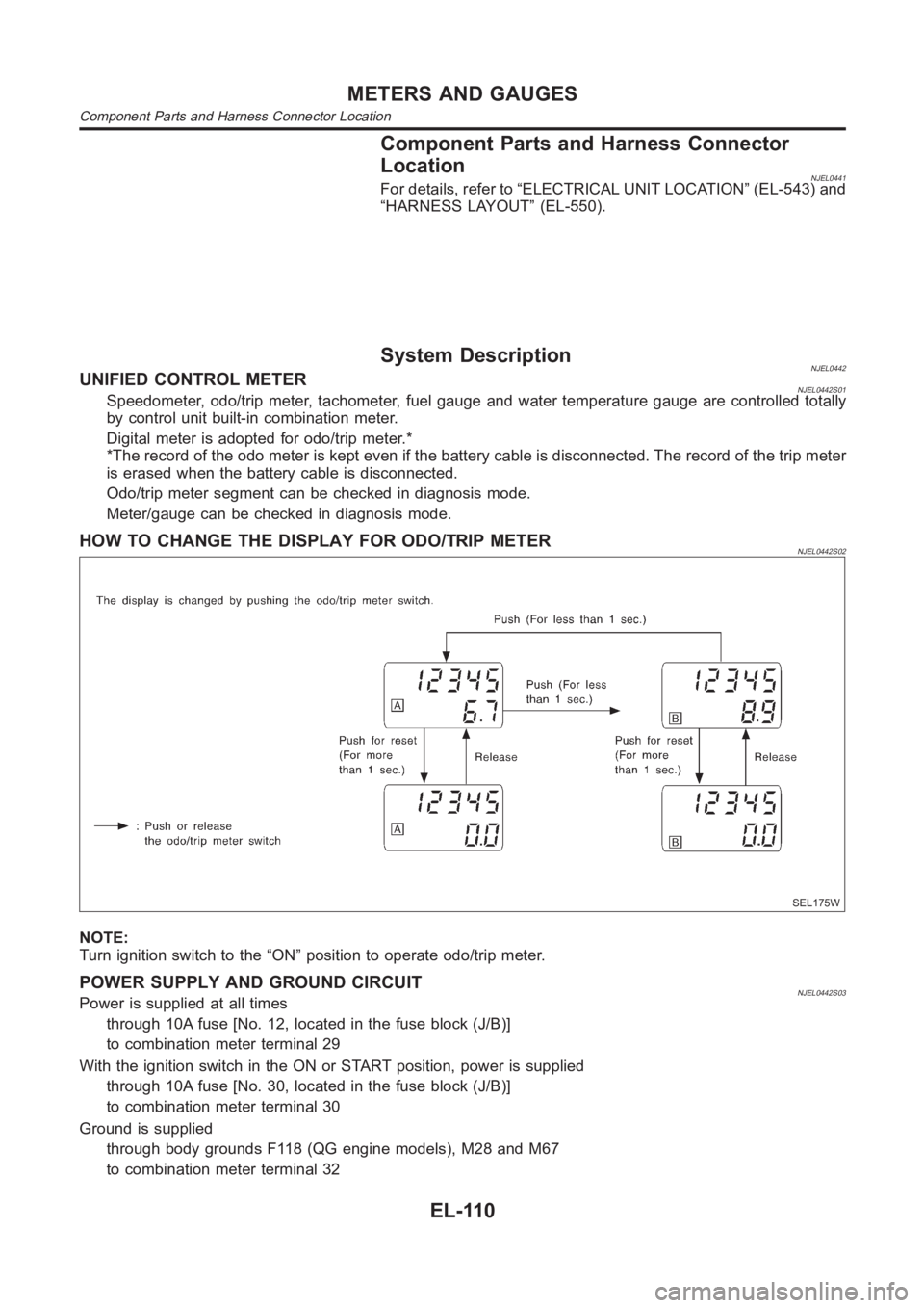
HOW TO CHANGE THE DISPLAY FOR ODO/TRIP METERNJEL0442S02
SEL175W
NOTE:
Turn ignition switch to the “ON” position to operate odo/trip meter.
POWER SUPPLY AND GROUND CIRCUITNJEL0442S03Power is supplied at all times
through 10A fuse [No. 12, located in the fuse block (J/B)]
to combination meter terminal 29
With the ignition switch in the ON or START position, power is supplied
through 10A fuse [No. 30, located in the fuse block (J/B)]
to combination meter terminal 30
Ground is supplied
through body grounds F118 (QG engine models), M28 and M67
to combination meter terminal 32
METERS AND GAUGES
Component Parts and Harness Connector Location
EL-110
Page 2447 of 3189
WATER TEMPERATURE GAUGE (QG AND YD ENGINE MODELS WITH COMMON RAIL)NJEL0442S09The water temperature gauge indicates the engine coolant temperature.
ECM provides a engine coolant temperature signal to combination meter forwater temperature gauge with
CAN communication line.
WATER TEMPERATURE GAUGE (YD ENGINE MODELS WITHOUT COMMON RAIL)NJEL0442S04The water temperature gauge indicates the engine coolant temperature. The reading on the gauge is based
on the resistance of the thermal transmitter.
As the temperature of the coolant increases, the resistance of the thermaltransmitter decreases. A variable
ground is supplied to terminal 35 of the combination meter for the water temperature gauge. The needle on
the gauge moves from “C” to “H”.
TACHOMETER (QG AND YD ENGINE MODELS WITH COMMON RAIL)NJEL0442S10The tachometer indicates engine speed in revolution per minutes (rpm). ECM provides an engine speed sig-
nal to combination meter for tachometer with CAN communication line.
TACHOMETER (YD ENGINE MODELS WITHOUT COMMON RAIL)NJEL0442S05The tachometer indicates engine speed in revolutions per minute (rpm).
The tachometer is regulated by a signal
from terminal 32 (Gasoline engine models) or 439 (Diesel engine models) ofthe ECM
to combination meter terminal 53 for the tachometer.
FUEL GAUGENJEL0442S06The fuel gauge indicates the approximate fuel level in the fuel tank.
The fuel gauge is regulated by a variable ground signal supplied
from body grounds F118 (QG engine models), M28 and M67
through terminals 33 and 32 of combination meter,
through terminal 1 of the fuel level sensor unit and
through terminal 4 of the fuel level sensor unit
to combination meter terminal 34 for the fuel gauge.
SPEEDOMETER (MODELS WITH ABS)NJEL0442S11The combination meter receives a signal from the ABS actuator and electricunit. The speedometer converts
the signal into the vehicle speed displayed.
SPEEDOMETER (MODELS WITHOUT ABS)NJEL0442S07The combination meter provides a voltage signal to the vehicle speed sensor for the speedometer.
The voltage is supplied
from combination meter terminal 13 for the speedometer
to terminal 1 of the vehicle speed sensor.
Ground is supplied
from body grounds F118 (QG engine models), M28 and M67
through terminals 32 and 14 of combination meter
to teminal 2 of the vehicle speed sensor.
The speedometer converts the voltage into the vehicle speed displayed.
GI
MA
EM
LC
EC
FE
CL
MT
AT
AX
SU
BR
ST
RS
BT
HA
SC
IDX
METERS AND GAUGES
System Description (Cont’d)
EL-111
Page 2460 of 3189
Models with ABS=NJEL0448S0402
1 ABS ACTUATOR AND ELECTRIC UNIT SYSTEM INSPECTION
Perform ABS actuator and electric unit self-diagnosis.
Refer to BR-55, “CONSULT-II Functions”.
OK or NG
OK GO TO 2.
NG Check ABS control system. Refer to BR-62, “TROUBLE DIAGNOSIS — BASIC INSPEC-
TION”.
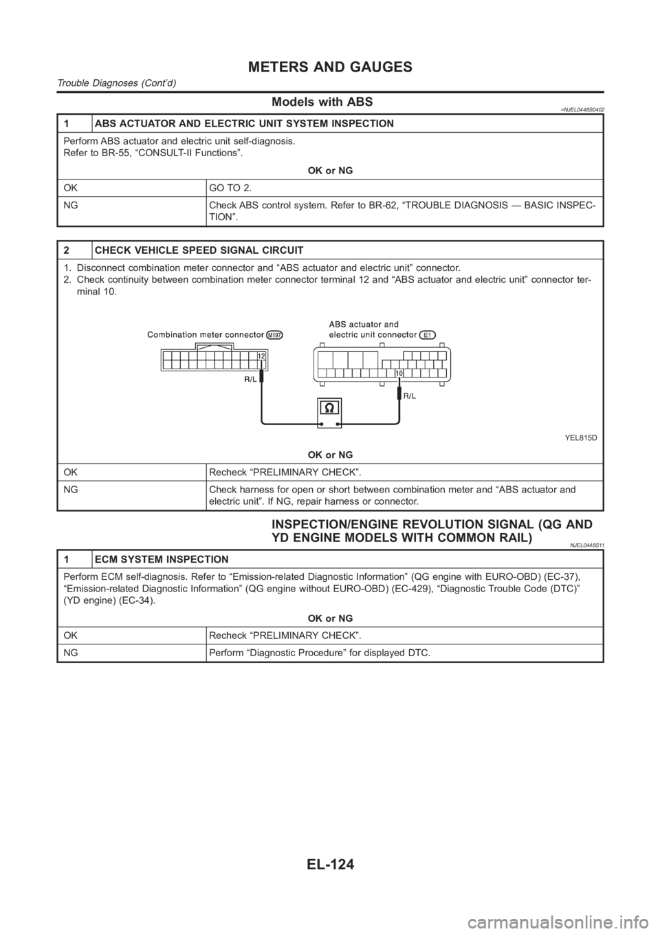
2 CHECK VEHICLE SPEED SIGNAL CIRCUIT
1. Disconnect combination meter connector and “ABS actuator and electricunit” connector.
2. Check continuity between combination meter connector terminal 12 and “ABS actuator and electric unit” connector ter-
minal 10.
YEL815D
OK or NG
OK Recheck “PRELIMINARY CHECK”.
NG Check harness for open or short between combination meter and “ABS actuator and
electric unit”. If NG, repair harness or connector.
INSPECTION/ENGINE REVOLUTION SIGNAL (QG AND
YD ENGINE MODELS WITH COMMON RAIL)
NJEL0448S11
1 ECM SYSTEM INSPECTION
Perform ECM self-diagnosis. Refer to “Emission-related Diagnostic Information” (QG engine with EURO-OBD) (EC-37),
“Emission-related Diagnostic Information” (QG engine without EURO-OBD) (EC-429), “Diagnostic Trouble Code (DTC)”
(YD engine) (EC-34).
OK or NG
OK Recheck “PRELIMINARY CHECK”.
NG Perform “Diagnostic Procedure” for displayed DTC.
METERS AND GAUGES
Trouble Diagnoses (Cont’d)
EL-124
Page 2464 of 3189
SEL498X
Electrical Components Inspection=NJEL0449FUEL LEVEL SENSOR UNIT CHECKNJEL0449S02For removal, refer to FE-5, FE-17, “FUEL SYSTEM”.
Check the resistance between terminals 4 and 1.
Ohmmeter
Float position mm (in)Resistance
valueΩ
(+) (−)
41*1 Full 142.4 (5.606) Approx. 4 - 6
*2 1/2 88.6 (3.488) 32 - 33
*3 Empty 11.0 (0.433) 80 - 83
*1 and *3: When float rod is in contact with stopper.
MEL424F
THERMAL TRANSMITTER CHECKNJEL0449S03YD Engine Models without Common Rail OnlyNJEL0449S0301Check the resistance between the terminals of thermal transmitter
and body ground.
Water temperature Resistance
65°C (149°F) Approx. 1,179 - 1,417Ω
91°C (196°F) Approx. 474 - 568Ω
CEL219AA
VEHICLE SPEED SENSOR SIGNAL CHECKNJEL0449S04Models without ABS OnlyNJEL0449S04011. Remove vehicle speed sensor from transmission.
2. Turn vehicle speed sensor pinion quickly and measure voltage
across 1 and 2.
METERS AND GAUGES
Electrical Components Inspection
EL-128
Page 2471 of 3189
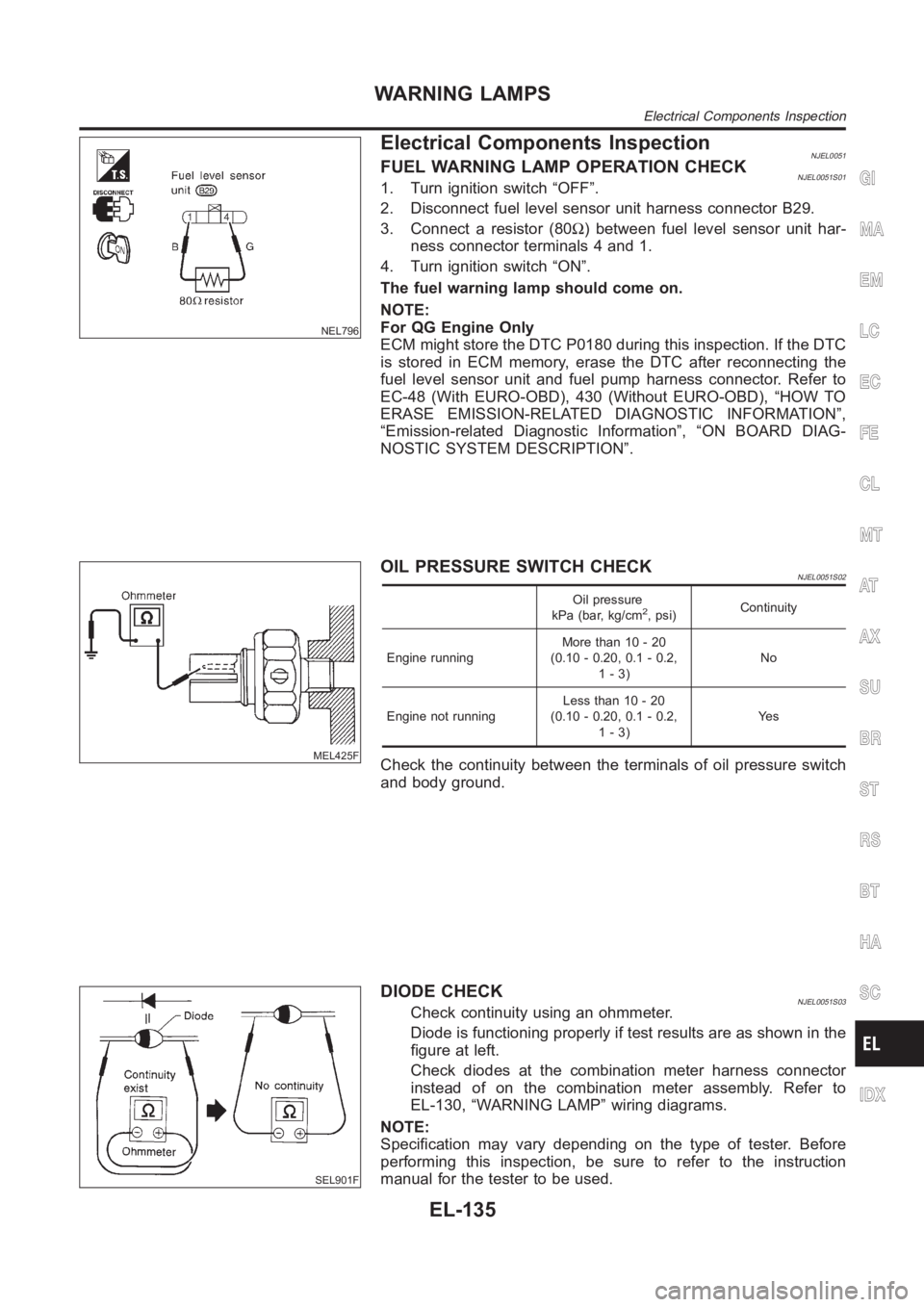
NEL796
Electrical Components InspectionNJEL0051FUEL WARNING LAMP OPERATION CHECKNJEL0051S011. Turn ignition switch “OFF”.
2. Disconnect fuel level sensor unit harness connector B29.
3. Connect a resistor (80Ω) between fuel level sensor unit har-
ness connector terminals 4 and 1.
4. Turn ignition switch “ON”.
The fuel warning lamp should come on.
NOTE:
For QG Engine Only
ECM might store the DTC P0180 during this inspection. If the DTC
is stored in ECM memory, erase the DTC after reconnecting the
fuel level sensor unit and fuel pump harness connector. Refer to
EC-48 (With EURO-OBD), 430 (Without EURO-OBD), “HOW TO
ERASE EMISSION-RELATED DIAGNOSTIC INFORMATION”,
“Emission-related Diagnostic Information”, “ON BOARD DIAG-
NOSTIC SYSTEM DESCRIPTION”.
MEL425F
OIL PRESSURE SWITCH CHECKNJEL0051S02
Oil pressure
kPa (bar, kg/cm2, psi)Continuity
Engine runningMore than 10 - 20
(0.10 - 0.20, 0.1 - 0.2,
1-3)No
Engine not runningLess than 10 - 20
(0.10 - 0.20, 0.1 - 0.2,
1-3)Ye s
Check the continuity between the terminals of oil pressure switch
and body ground.
SEL901F
DIODE CHECKNJEL0051S03Check continuity using an ohmmeter.
Diode is functioning properly if test results are as shown in the
figure at left.
Check diodes at the combination meter harness connector
instead of on the combination meter assembly. Refer to
EL-130, “WARNING LAMP” wiring diagrams.
NOTE:
Specification may vary depending on the type of tester. Before
performing this inspection, be sure to refer to the instruction
manual for the tester to be used.
GI
MA
EM
LC
EC
FE
CL
MT
AT
AX
SU
BR
ST
RS
BT
HA
SC
IDX
WARNING LAMPS
Electrical Components Inspection
EL-135
Page 2525 of 3189
SEL970W
Electrical Components Inspection=NJEL0076REAR WINDOW DEFOGGER RELAYNJEL0076S01Check continuity between terminals 3 and 5, 6 and 7.
Condition Continuity
12V direct current supply between ter-
minals 1 and 2Ye s
No current supply No
YEL824D
REAR WINDOW DEFOGGER SWITCH (MANUAL A/C
MODELS)
NJEL0076S02Check continuity between terminals when rear window defogger
switch is pushed and released.
Terminals Condition Continuity
3-5Rear window defogger
switch is pushed.Ye s
Rear window defogger
switch is released.No
SKIA1435E
REAR WINDOW DEFOGGER SWITCH (AUTO A/C
MODELS)
NJEL0076S03Check continuity between Multifunction switch and body ground
when rear window defogger switch is operated.
Terminals
Continuity
Multifunction switch
(−)
Connector Terminal (wire color) Press switch Release switch
M97 9 (L/Y) Ground YES NO
GI
MA
EM
LC
EC
FE
CL
MT
AT
AX
SU
BR
ST
RS
BT
HA
SC
IDX
REAR WINDOW DEFOGGER
Electrical Components Inspection
EL-189