2003 NISSAN ALMERA N16 relay
[x] Cancel search: relayPage 1995 of 3189
REFRIGERATION SYSTEM
ATC-15
C
D
E
F
G
H
I
K
L
MA
B
AT C
REFRIGERATION SYSTEMPFP:KA990
Refrigerant CycleEJS001Z0
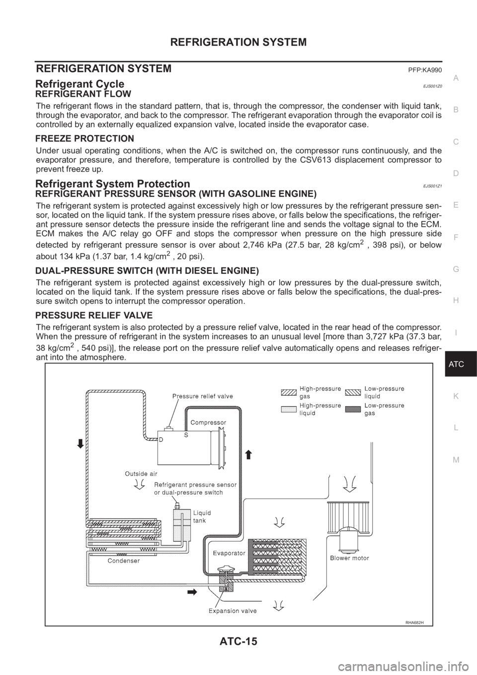
REFRIGERANT FLOW
The refrigerant flows in the standard pattern, that is, through the compressor, the condenser with liquid tank,
through the evaporator, and back to the compressor. The refrigerant evaporation through the evaporator coil is
controlled by an externally equalized expansion valve, located inside the evaporator case.
FREEZE PROTECTION
Under usual operating conditions, when the A/C is switched on, the compressor runs continuously, and the
evaporator pressure, and therefore, temperature is controlled by the CSV613 displacement compressor to
prevent freeze up.
Refrigerant System ProtectionEJS001Z1
REFRIGERANT PRESSURE SENSOR (WITH GASOLINE ENGINE)
The refrigerant system is protected against excessively high or low pressures by the refrigerant pressure sen-
sor, located on the liquid tank. If the system pressure rises above, or falls below the specifications, the refriger-
ant pressure sensor detects the pressure inside the refrigerant line and sends the voltage signal to the ECM.
ECM makes the A/C relay go OFF and stops the compressor when pressure on the high pressure side
detected by refrigerant pressure sensor is over about 2,746 kPa (27.5 bar, 28 kg/cm
2 , 398 psi), or below
about 134 kPa (1.37 bar, 1.4 kg/cm
2 , 20 psi).
DUAL-PRESSURE SWITCH (WITH DIESEL ENGINE)
The refrigerant system is protected against excessively high or low pressures by the dual-pressure switch,
located on the liquid tank. If the system pressure rises above or falls below the specifications, the dual-pres-
sure switch opens to interrupt the compressor operation.
PRESSURE RELIEF VALVE
The refrigerant system is also protected by a pressure relief valve, located in the rear head of the compressor.
When the pressure of refrigerant in the system increases to an unusual level [more than 3,727 kPa (37.3 bar,
38 kg/cm
2 , 540 psi)], the release port on the pressure relief valve automatically opens and releases refriger-
ant into the atmosphere.
RHA682H
Page 2057 of 3189
TROUBLE DIAGNOSIS
ATC-77
C
D
E
F
G
H
I
K
L
MA
B
AT C
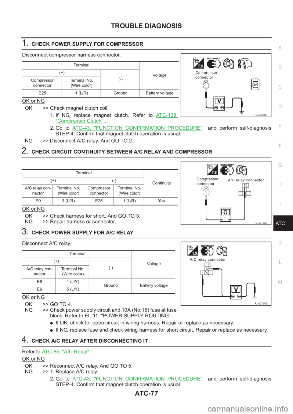
1.CHECK POWER SUPPLY FOR COMPRESSOR
Disconnect compressor harness connector.
OK or NG
OK >> Check magnet clutch coil.
1. If NG, replace magnet clutch. Refer to ATC-138,
"Compressor Clutch" .
2. Go to AT C - 4 3 , "
FUNCTION CONFIRMATION PROCEDURE" and perform self-diagnosis
STEP-4. Confirm that magnet clutch operation is usual.
NG >> Disconnect A/C relay. And GO TO 2.
2.CHECK CIRCUIT CONTINUITY BETWEEN A/C RELAY AND COMPRESSOR
OK or NG
OK >> Check harness for short. And GO TO 3.
NG >> Repair harness or connector.
3.CHECK POWER SUPPLY FOR A/C RELAY
Disconnect A/C relay.
OK or NG
OK >> GO TO 4.
NG >> Check power supply circuit and 10A (No.15) fuse at fuse
block. Refer to EL-11, "POWER SUPPLY ROUTING" .
●If OK, check for open circuit in wiring harness. Repair or replace as necessary.
●If NG, replace fuse and check wiring harness for short circuit. Repair or replace as necessary.
4.CHECK A/C RELAY AFTER DISCONNECTING IT
Refer to ATC-85, "
A/C Relay" .
OK or NG
OK >> Reconnect A/C relay. And GO TO 5.
NG >> 1. Replace A/C relay.
2. Go to AT C - 4 3 , "
FUNCTION CONFIRMATION PROCEDURE" and perform self-diagnosis
STEP-4. Confirm that magnet clutch operation is usual.
Terminal
Vo lta g e (+)
(-)
Compressor
connectorTe r m i n a l N o .
(Wire color)
E25 1 (L/R) Ground Battery voltage
RJIA0295E
Terminal
Continuity (+) (-)
A/C relay con-
nectorTerminal No.
(Wire color)Compressor
connectorTerminal No.
(Wire color)
E9 3 (L/R) E25 1 (L/R) Yes
RJIA0793E
Terminal
Vo l ta g e (+)
(-)
A/C relay con-
nectorTerminal No.
(Wire color)
E9 1 (L/Y)
Ground Battery voltage
E9 5 (L/Y)
RJIA0794E
Page 2058 of 3189
ATC-78
TROUBLE DIAGNOSIS
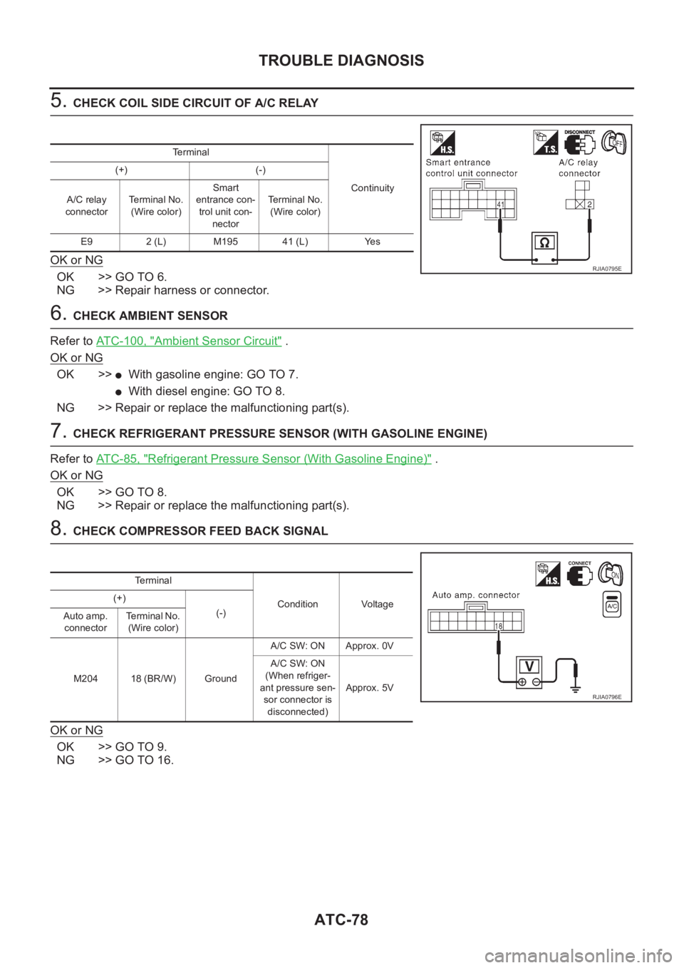
5. CHECK COIL SIDE CIRCUIT OF A/C RELAY
OK or NG
OK >> GO TO 6.
NG >> Repair harness or connector.
6. CHECK AMBIENT SENSOR
Refer to ATC-100, "
Ambient Sensor Circuit" .
OK or NG
OK >>●With gasoline engine: GO TO 7.
●With diesel engine: GO TO 8.
NG >> Repair or replace the malfunctioning part(s).
7. CHECK REFRIGERANT PRESSURE SENSOR (WITH GASOLINE ENGINE)
Refer to AT C - 8 5 , "
Refrigerant Pressure Sensor (With Gasoline Engine)" .
OK or NG
OK >> GO TO 8.
NG >> Repair or replace the malfunctioning part(s).
8. CHECK COMPRESSOR FEED BACK SIGNAL
OK or NG
OK >> GO TO 9.
NG >> GO TO 16.
Terminal
Continuity (+) (-)
A/C relay
connectorTerminal No.
(Wire color)Smart
entrance con-
trol unit con-
nectorTerminal No.
(Wire color)
E9 2 (L) M195 41 (L) Yes
RJIA0795E
Terminal
Condition Voltage (+)
(-)
Auto amp.
connectorTerminal No.
(Wire color)
M204 18 (BR/W) GroundA/C SW: ON Approx. 0V
A/C SW: ON
(When refriger-
ant pressure sen-
sor connector is
disconnected)Approx. 5V
RJIA0796E
Page 2062 of 3189
ATC-82
TROUBLE DIAGNOSIS
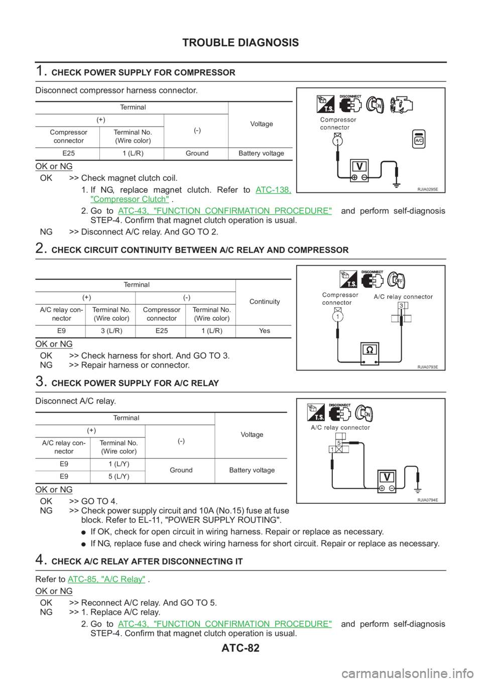
1. CHECK POWER SUPPLY FOR COMPRESSOR
Disconnect compressor harness connector.
OK or NG
OK >> Check magnet clutch coil.
1. If NG, replace magnet clutch. Refer to ATC-138,
"Compressor Clutch" .
2. Go to AT C - 4 3 , "
FUNCTION CONFIRMATION PROCEDURE" and perform self-diagnosis
STEP-4. Confirm that magnet clutch operation is usual.
NG >> Disconnect A/C relay. And GO TO 2.
2. CHECK CIRCUIT CONTINUITY BETWEEN A/C RELAY AND COMPRESSOR
OK or NG
OK >> Check harness for short. And GO TO 3.
NG >> Repair harness or connector.
3. CHECK POWER SUPPLY FOR A/C RELAY
Disconnect A/C relay.
OK or NG
OK >> GO TO 4.
NG >> Check power supply circuit and 10A (No.15) fuse at fuse
block. Refer to EL-11, "POWER SUPPLY ROUTING".
●If OK, check for open circuit in wiring harness. Repair or replace as necessary.
●If NG, replace fuse and check wiring harness for short circuit. Repair or replace as necessary.
4. CHECK A/C RELAY AFTER DISCONNECTING IT
Refer to AT C - 8 5 , "
A/C Relay" .
OK or NG
OK >> Reconnect A/C relay. And GO TO 5.
NG >> 1. Replace A/C relay.
2. Go to AT C - 4 3 , "
FUNCTION CONFIRMATION PROCEDURE" and perform self-diagnosis
STEP-4. Confirm that magnet clutch operation is usual.
Te r m i n a l
Voltag e (+)
(-)
Compressor
connectorTerminal No.
(Wire color)
E25 1 (L/R) Ground Battery voltage
RJIA0295E
Terminal
Continuity (+) (-)
A/C relay con-
nectorTerminal No.
(Wire color)Compressor
connectorTe r m i n a l N o .
(Wire color)
E9 3 (L/R) E25 1 (L/R) Yes
RJIA0793E
Te r m i n a l
Voltage (+)
(-)
A/C relay con-
nectorTerminal No.
(Wire color)
E9 1 (L/Y)
Ground Battery voltage
E9 5 (L/Y)
RJIA0794E
Page 2063 of 3189
TROUBLE DIAGNOSIS
ATC-83
C
D
E
F
G
H
I
K
L
MA
B
AT C
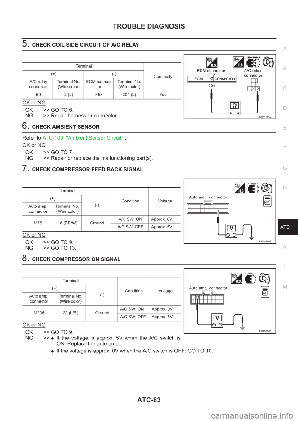
5.CHECK COIL SIDE CIRCUIT OF A/C RELAY
OK or NG
OK >> GO TO 6.
NG >> Repair harness or connector.
6.CHECK AMBIENT SENSOR
Refer to ATC-100, "
Ambient Sensor Circuit" .
OK or NG
OK >> GO TO 7.
NG >> Repair or replace the malfunctioning part(s).
7.CHECK COMPRESSOR FEED BACK SIGNAL
OK or NG
OK >> GO TO 9.
NG >> GO TO 13.
8.CHECK COMPRESSOR ON SIGNAL
OK or NG
OK >> GO TO 9.
NG >>
●If the voltage is approx. 5V when the A/C switch is
ON: Replace the auto amp.
●If the voltage is approx. 0V when the A/C switch is OFF: GO TO 10.
Terminal
Continuity (+) (-)
A/C relay
connectorTerminal No.
(Wire color)ECM connec-
torTerminal No.
(Wire color)
E9 2 (L) F58 204 (L) Yes
RJIA1705E
Terminal
Condition Voltage (+)
(-)
Auto amp.
connectorTe r m i n a l N o .
(Wire color)
M75 18 (BR/W) GroundA/C SW: ON Approx. 0V
A/C SW: OFF Approx. 5V
RJIA0796E
Terminal
Condition Voltage (+)
(-)
Auto amp.
connectorTerminal No.
(Wire color)
M205 22 (L/R) GroundA/C SW: ON Approx. 0V
A/C SW: OFF Approx. 5V
RJIA0798E
Page 2065 of 3189
TROUBLE DIAGNOSIS
ATC-85
C
D
E
F
G
H
I
K
L
MA
B
AT C
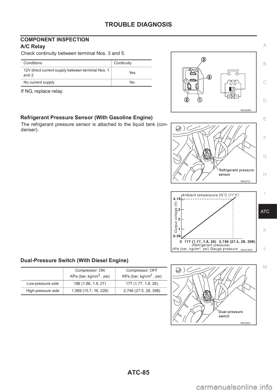
COMPONENT INSPECTION
A/C Relay
Check continuity between terminal Nos. 3 and 5.
If NG, replace relay.
Refrigerant Pressure Sensor (With Gasoline Engine)
The refrigerant pressure sensor is attached to the liquid tank (con-
denser).
Dual-Pressure Switch (With Diesel Engine)
Conditions Continuity
12V direct current supply between terminal Nos. 1
and 2Ye s
No current supply No
RHA638H
RHA272I
SHA315FD
Compressor: ON
KPa (bar, kg/cm2 , psi)Compressor: OFF
KPa (bar, kg/cm2 , psi)
Low-pressure side 186 (1.86, 1.9, 27) 177 (1.77, 1.8, 26)
High-pressure side 1,569 (15.7, 16, 228) 2,746 (27.5, 28, 398)
RHA282I
Page 2230 of 3189
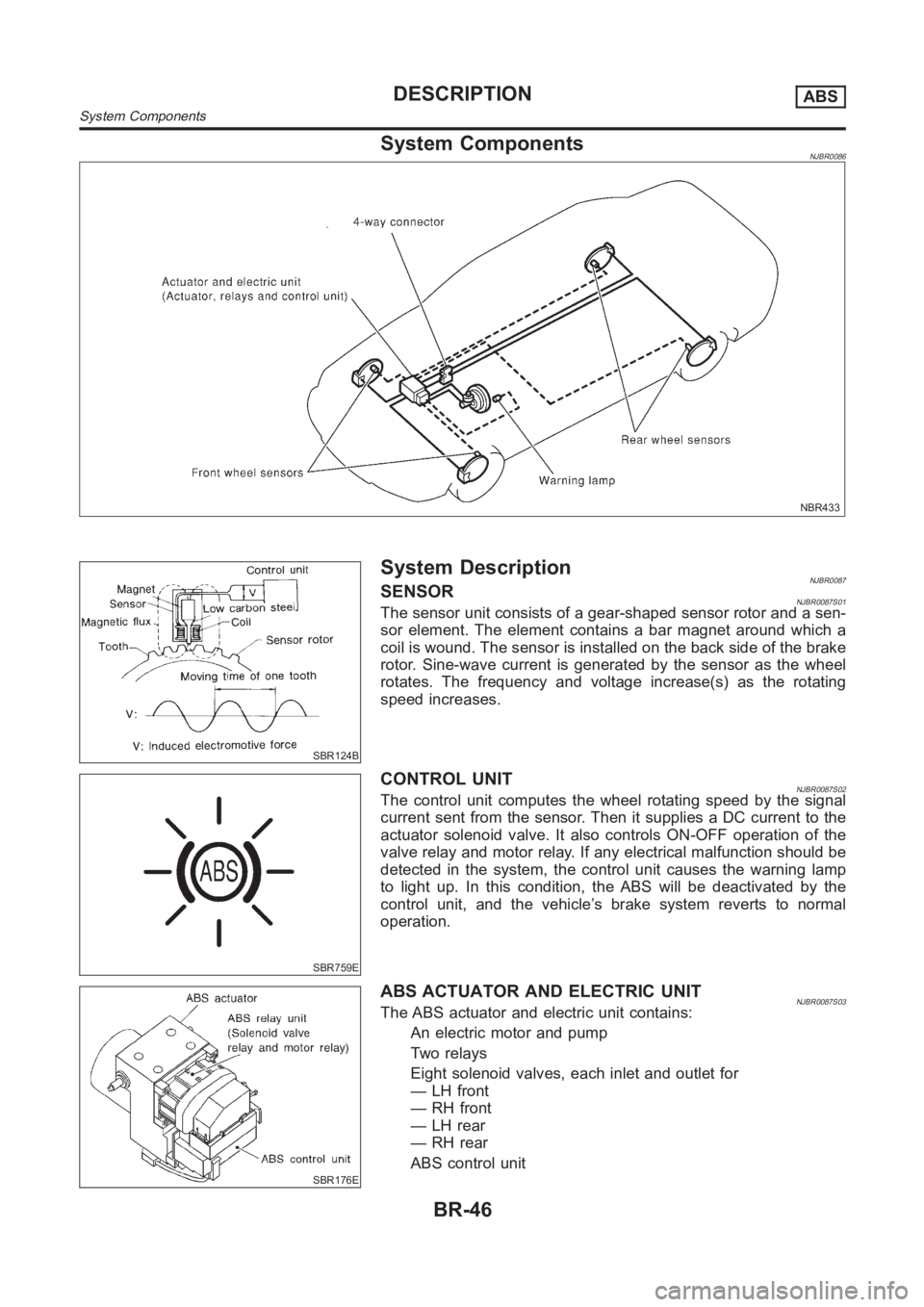
System ComponentsNJBR0086
NBR433
SBR124B
System DescriptionNJBR0087SENSORNJBR0087S01The sensor unit consists of a gear-shaped sensor rotor and a sen-
sor element. The element contains a bar magnet around which a
coil is wound. The sensor is installed on the back side of the brake
rotor. Sine-wave current is generated by the sensor as the wheel
rotates. The frequency and voltage increase(s) as the rotating
speed increases.
SBR759E
CONTROL UNITNJBR0087S02The control unit computes the wheel rotating speed by the signal
current sent from the sensor. Then it supplies a DC current to the
actuator solenoid valve. It also controls ON-OFF operation of the
valve relay and motor relay. If any electrical malfunction should be
detected in the system, the control unit causes the warning lamp
to light up. In this condition, the ABS will be deactivated by the
control unit, and the vehicle’s brake system reverts to normal
operation.
SBR176E
ABS ACTUATOR AND ELECTRIC UNITNJBR0087S03The ABS actuator and electric unit contains:
An electric motor and pump
Two relays
Eight solenoid valves, each inlet and outlet for
— LH front
—RHfront
— LH rear
— RH rear
ABS control unit
DESCRIPTIONABS
System Components
BR-46
Page 2238 of 3189
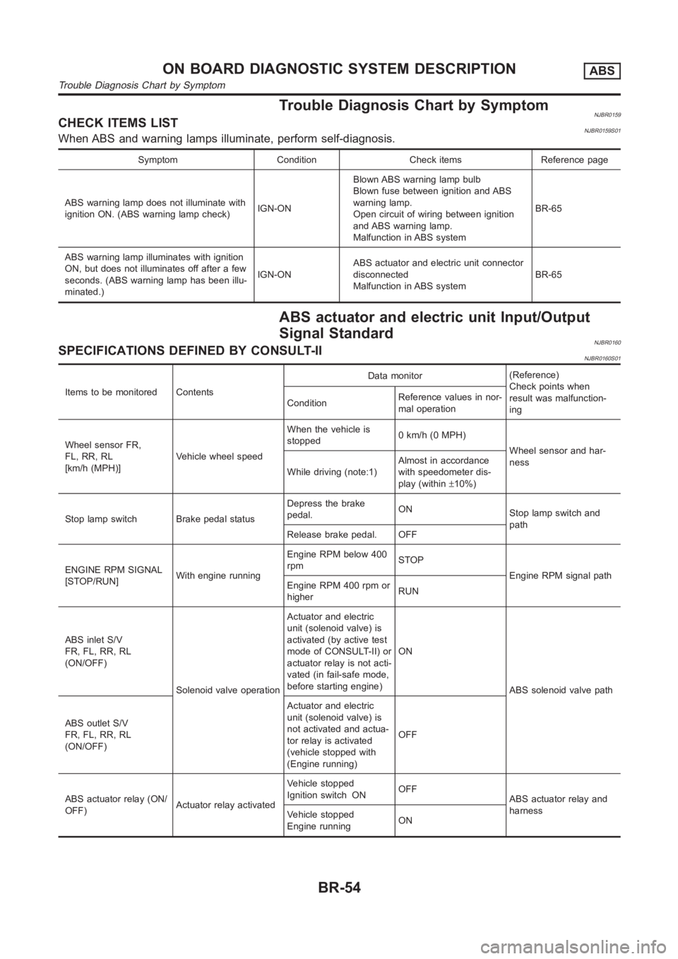
Trouble Diagnosis Chart by SymptomNJBR0159CHECK ITEMS LISTNJBR0159S01When ABS and warning lamps illuminate, perform self-diagnosis.
Symptom Condition Check items Reference page
ABS warning lamp does not illuminate with
ignition ON. (ABS warning lamp check)IGN-ONBlown ABS warning lamp bulb
Blown fuse between ignition and ABS
warning lamp.
Open circuit of wiring between ignition
and ABS warning lamp.
Malfunction in ABS systemBR-65
ABS warning lamp illuminates with ignition
ON, but does not illuminates off after a few
seconds. (ABS warning lamp has been illu-
minated.)IGN-ONABS actuator and electric unit connector
disconnected
Malfunction in ABS systemBR-65
ABS actuator and electric unit Input/Output
Signal Standard
NJBR0160SPECIFICATIONS DEFINED BY CONSULT-IINJBR0160S01
Items to be monitored ContentsData monitor(Reference)
Check points when
result was malfunction-
ing ConditionReference values in nor-
mal operation
Wheel sensor FR,
FL, RR, RL
[km/h (MPH)]Vehicle wheel speedWhen the vehicle is
stopped0 km/h (0 MPH)
Wheel sensor and har-
ness
While driving (note:1)Almost in accordance
with speedometer dis-
play (within±10%)
Stop lamp switch Brake pedal statusDepress the brake
pedal.ON
Stop lamp switch and
path
Release brake pedal. OFF
ENGINE RPM SIGNAL
[STOP/RUN]With engine runningEngine RPM below 400
rpmSTOP
Engine RPM signal path
Engine RPM 400 rpm or
higherRUN
ABS inlet S/V
FR, FL, RR, RL
(ON/OFF)
Solenoid valve operationActuator and electric
unit (solenoid valve) is
activated (by active test
mode of CONSULT-II) or
actuator relay is not acti-
vated (in fail-safe mode,
before starting engine)ON
ABS solenoid valve path
ABS outlet S/V
FR, FL, RR, RL
(ON/OFF)Actuator and electric
unit (solenoid valve) is
not activated and actua-
tor relay is activated
(vehicle stopped with
(Engine running)OFF
ABS actuator relay (ON/
OFF)Actuator relay activatedVehicle stopped
Ignition switch ONOFF
ABS actuator relay and
harness
Vehicle stopped
Engine runningON
ON BOARD DIAGNOSTIC SYSTEM DESCRIPTIONABS
Trouble Diagnosis Chart by Symptom
BR-54