Page 1234 of 3189
6 DETECT MALFUNCTIONING PART
Check the following.
Harness connectors E174, M159 (LHD models)
Harness connectors E251, M182 (RHD models)
Harness connectors M63, F102
Harness for open and short between ECM and ECM relay
Repair open circuit or short to ground or short to power in harness or connectors.
7 CHECK ECM RELAY
1. Apply 12V direct current between ECM relay terminals 1 and 2.
2. Check continuity between ECM relay terminals 3 and 5, 6 and 7.
SEF296X
OK or NG
OK GO TO 8.
NG Replace ECM relay.
8 CHECK INTERMITTENT INCIDENT
Refer to “TROUBLE DIAGNOSIS FOR INTERMITTENT INCIDENT”, EC-71.
INSPECTION END
DTC P1620 ECM RLYYD
Diagnostic Procedure (Cont’d)
EC-180
Page 1242 of 3189

DescriptionNJEC0760SYSTEM DESCRIPTIONNJEC0760S01
Sensor Input Signal to ECMECM
Func-
tionActuator
Crankshaft position sensor
(TDC)Engine speed
Glow
controlGlow lamp,
Glow relay
"
Glow plugs Engine coolant tempera-
ture sensorEngine coolant tem-
perature
When engine coolant temperature is more than approximately
75°C (167°F), the glow relay turns off.
When coolant temperature is lower than approximately 75°C
(167°F):
Ignition switch ON
After ignition switch has turned to ON, the glow relay turns ON
for a certain period of time in relation to engine coolant
temperature, allowing current to flow through glow plug.
Cranking
The glow relay turns ON, allowing current to flow through glow
plug.
Starting
After engine has started, current continues to flow through
glow plug (after-glow mode) for a certain period in relation to
engine coolant temperature.
The glow indicator lamp turns ON for a certain period of time in
relation to engine cooalnt temperature at the time glow relay is
turned ON.
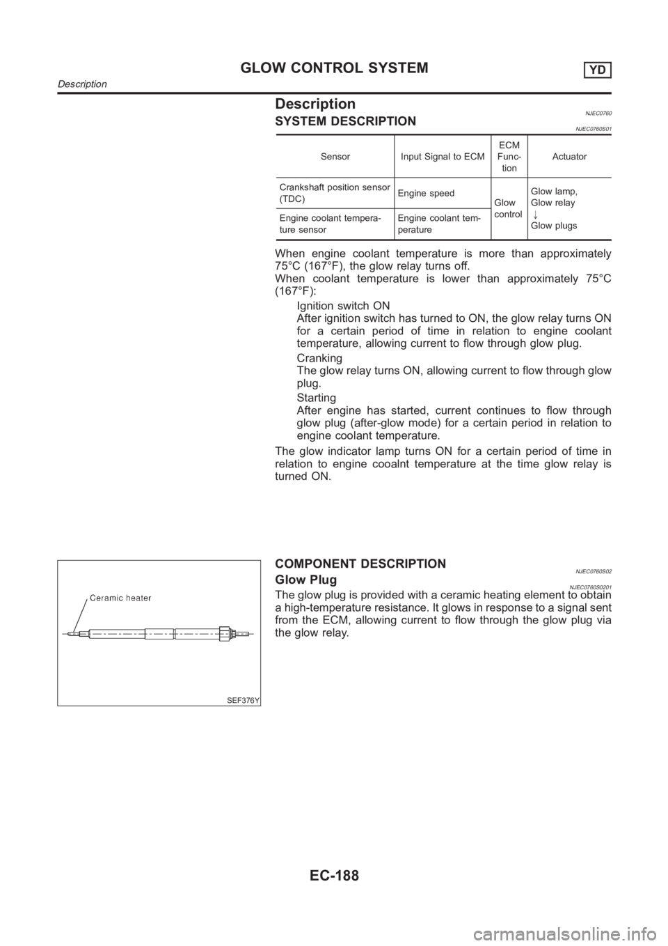
SEF376Y
COMPONENT DESCRIPTIONNJEC0760S02Glow PlugNJEC0760S0201The glow plug is provided with a ceramic heating element to obtain
a high-temperature resistance. It glows in response to a signal sent
from the ECM, allowing current to flow through the glow plug via
the glow relay.
GLOW CONTROL SYSTEMYD
Description
EC-188
Page 1243 of 3189
ECM Terminals and Reference ValueNJEC0761Specification data are reference values and are measured between each terminal and ground.
CAUTION:
Do not use ECM ground terminals when measuring input/output voltage. Doing so may result in dam-
age to the ECM’s transistor. Use a ground other than ECM terminals, such as the ground.
TERMI-
NAL
NO.WIRE
COLORITEM CONDITION DATA (DC Voltage)
214 W/B Glow relay Refer to “SYSTEM DESCRIPTION”, EC-188.
508 OR Glow indicator lamp[Ignition switch “ON”]
Glow indicator lamp is “ON”Approximately 1V
[Ignition switch “ON”]
Glow indicator lamp is “OFF”BATTERY VOLTAGE
(11 - 14V)
GI
MA
EM
LC
FE
CL
MT
AT
AX
SU
BR
ST
RS
BT
HA
SC
EL
IDX
GLOW CONTROL SYSTEMYD
ECM Terminals and Reference Value
EC-189
Page 1248 of 3189

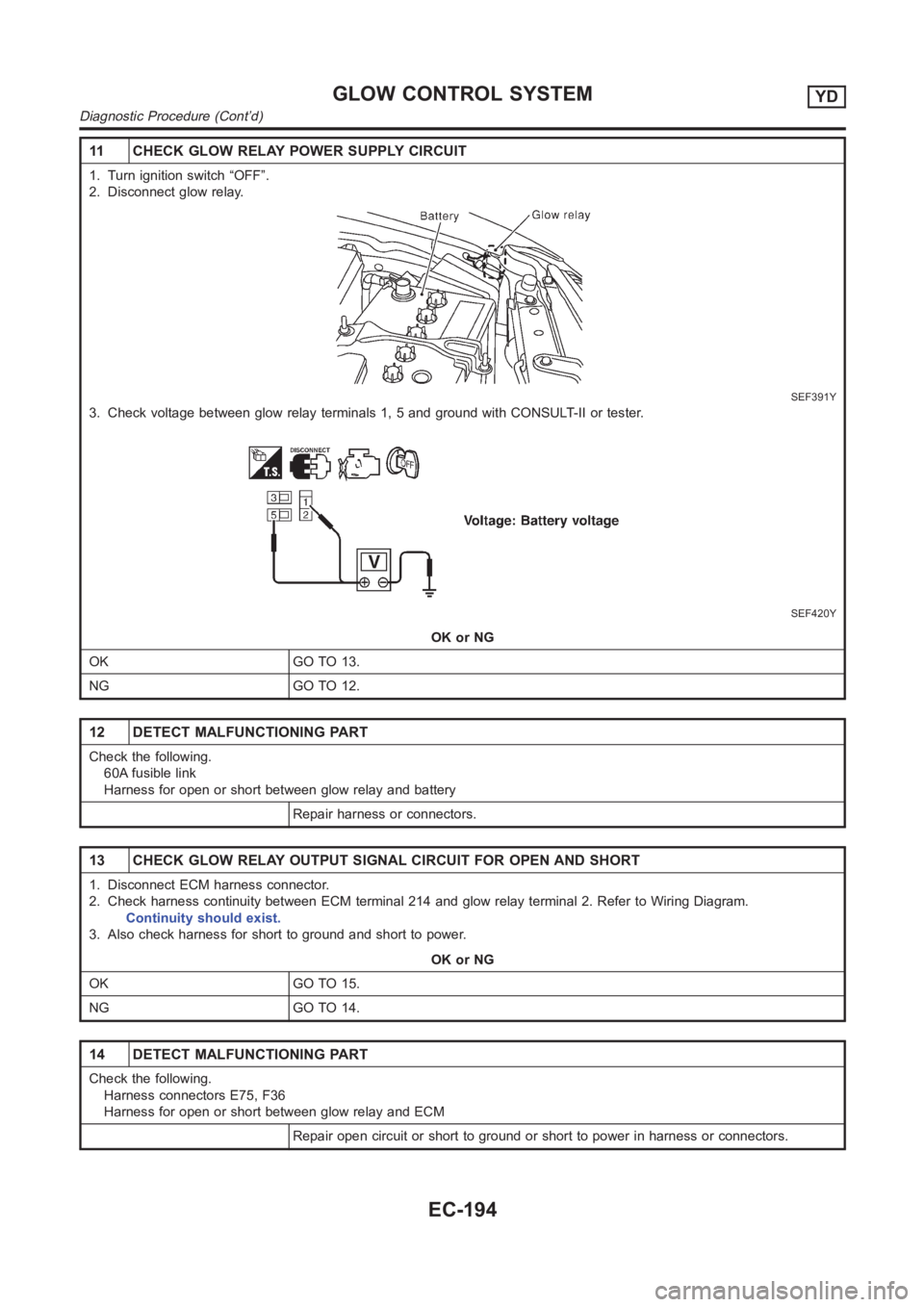
11 CHECK GLOW RELAY POWER SUPPLY CIRCUIT
1. Turn ignition switch “OFF”.
2. Disconnect glow relay.
SEF391Y
3. Check voltage between glow relay terminals 1, 5 and ground with CONSULT-II or tester.
SEF420Y
OK or NG
OK GO TO 13.
NG GO TO 12.
12 DETECT MALFUNCTIONING PART
Check the following.
60A fusible link
Harness for open or short between glow relay and battery
Repair harness or connectors.
13 CHECK GLOW RELAY OUTPUT SIGNAL CIRCUIT FOR OPEN AND SHORT
1. Disconnect ECM harness connector.
2. Check harness continuity between ECM terminal 214 and glow relay terminal 2. Refer to Wiring Diagram.
Continuity should exist.
3. Also check harness for short to ground and short to power.
OK or NG
OK GO TO 15.
NG GO TO 14.
14 DETECT MALFUNCTIONING PART
Check the following.
Harness connectors E75, F36
Harness for open or short between glow relay and ECM
Repair open circuit or short to ground or short to power in harness or connectors.
GLOW CONTROL SYSTEMYD
Diagnostic Procedure (Cont’d)
EC-194
Page 1249 of 3189

15 CHECK HARNESS CONTINUITY BETWEEN GLOW RELAY AND GLOW PLUG FOR OPEN AND SHORT
1. Disconnect glow plug harness connector.
2. Check harness continuity between glow relay terminal 3 and glow plug harness connector. Refer to Wiring Diagram.
Continuity should exist.
3. Also check harness for short to ground and short to power.
OK or NG
OK GO TO 16.
NG Repair open circuit or short to ground or short to power in harness or connectors.
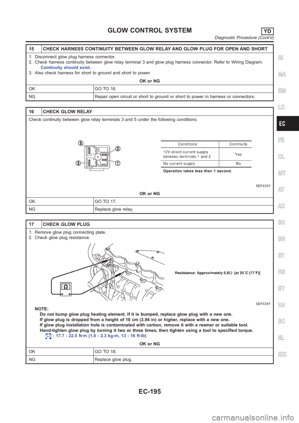
16 CHECK GLOW RELAY
Check continuity between glow relay terminals 3 and 5 under the following conditions.
SEF433Y
OK or NG
OK GO TO 17.
NG Replace glow relay.
17 CHECK GLOW PLUG
1. Remove glow plug connecting plate.
2. Check glow plug resistance.
SEF434Y
NOTE:
Do not bump glow plug heating element. If it is bumped, replace glow plug withanewone.
If glow plug is dropped from a height of 10 cm (3.94 in) or higher, replace with a new one.
If glow plug installation hole is contaminated with carbon, remove it witha reamer or suitable tool.
Hand-tighten glow plug by turning it two or three times, then tighten usinga tool to specified torque.
: 17.7 - 22.5 N·m (1.8 - 2.3 kg-m, 13 - 16 ft-lb)
OK or NG
OK GO TO 18.
NG Replace glow plug.
GI
MA
EM
LC
FE
CL
MT
AT
AX
SU
BR
ST
RS
BT
HA
SC
EL
IDX
GLOW CONTROL SYSTEMYD
Diagnostic Procedure (Cont’d)
EC-195
Page 1255 of 3189

3 CHECK EGR VOLUME CONTROL VALVE POWER SUPPLY CIRCUIT-II
1. Turn ignition switch “OFF”.
2. Disconnect ECM relay. (For ECM relay location, refer to “Engine ControlComponent Parts Location”.)
3. Check harness continuity between ECM relay terminal 5 and EGR volume control valve terminals 2 and 5. Refer to
Wiring Diagram.
Continuity should exist.
OK or NG
OK GO TO 5.
NG GO TO 4.
4 DETECT MALFUNCTIONING PART
Check the following.
Harness connectors E174, M159 (LHD models)
Harness connectors E251, M182 (RHD models)
Harness connectors M63, F102
Harness for open or short between ECM relay and EGR volume control valve
Repair open circuit or short to power in harness or connectors.
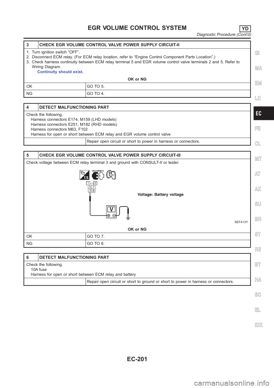
5 CHECK EGR VOLUME CONTROL VALVE POWER SUPPLY CIRCUIT-III
Check voltage between ECM relay terminal 3 and ground with CONSULT-II or tester.
SEF413Y
OK or NG
OK GO TO 7.
NG GO TO 6.
6 DETECT MALFUNCTIONING PART
Check the following.
10A fuse
Harness for open or short between ECM relay and battery
Repair open circuit or short to ground or short to power in harness or connectors.
GI
MA
EM
LC
FE
CL
MT
AT
AX
SU
BR
ST
RS
BT
HA
SC
EL
IDX
EGR VOLUME CONTROL SYSTEMYD
Diagnostic Procedure (Cont’d)
EC-201
Page 1256 of 3189
7 CHECK ECM RELAY
1. Apply 12V direct current between ECM relay terminals 1 and 2.
2. Check continuity between ECM relay terminals 3 and 5, 6 and 7.
SEF296X
OK or NG
OK GO TO 8.
NG Replace ECM relay.
8 CHECK EGR VOLUME CONTROL VALVE OUTPUT SIGNAL CIRCUIT FOR OPEN AND SHORT
1. Turn ignition switch “OFF”.
2. Disconnect ECM harness connector.
3. Check harness continuity between ECM terminals and EGR volume control valve terminals as follows.
Refer to Wiring Diagram.
MTBL0463
Continuity should exist.
4. Also check harness for short to ground and short to power.
OK or NG
OK GO TO 9.
NG Repair open circuit or short to ground or short to power in harness or connectors.
EGR VOLUME CONTROL SYSTEMYD
Diagnostic Procedure (Cont’d)
EC-202
Page 1858 of 3189
AT-402
[ALL]
A/T SHIFT LOCK SYSTEM
6. CHECK RELAY CIRCUIT
1. Turn ignition switch to ON.
Check voltage between terminal 2 - 3 and 4 - 3.
OK or NG
OK >> GO TO 7
NG >> Replace A/T device.
7. CHECK PARK POSITION SWITCH
Refer to AT-403, "
A/T DEVICE CHECK" .
OK or NG
OK >> GO TO 8
NG >> Replace A/T device.
8. CHECK SHIFT LOCK SOLENOID
Refer to AT-403, "
A/T DEVICE CHECK" .
OK or NG
OK >> GO TO 9
NG >> Replace A/T device.
9. SHIFT LOCK OPERATION
1. Reconnect shift lock harness connector.
2. Turn ignition switch from “OFF” to “ON” position. (Do not start engine.)
3. Recheck shift lock operation.
OK or NG
OK >>INSPECTION END
NG >> 1. Perform A/T device input/output signal inspection test.
2. If NG, recheck harness connector connection.
MCIB0005E