Page 1129 of 3189
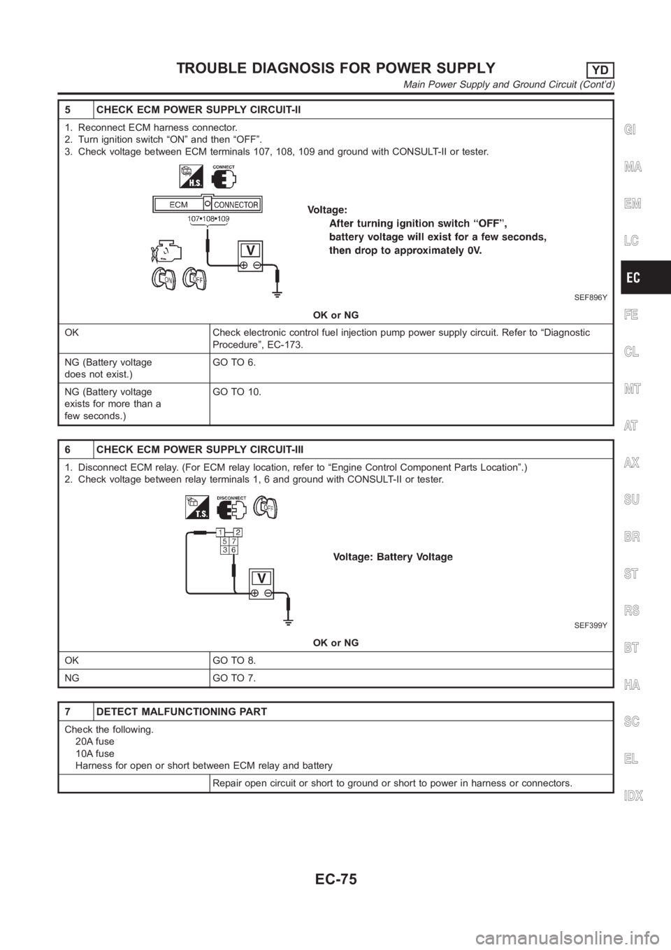
5 CHECK ECM POWER SUPPLY CIRCUIT-II
1. Reconnect ECM harness connector.
2. Turn ignition switch “ON” and then “OFF”.
3. Check voltage between ECM terminals 107, 108, 109 and ground with CONSULT-II or tester.
SEF896Y
OK or NG
OK Check electronic control fuel injection pump power supply circuit. Refer to “Diagnostic
Procedure”, EC-173.
NG (Battery voltage
does not exist.)GO TO 6.
NG (Battery voltage
exists for more than a
few seconds.)GO TO 10.
6 CHECK ECM POWER SUPPLY CIRCUIT-III
1. Disconnect ECM relay. (For ECM relay location, refer to “Engine ControlComponent Parts Location”.)
2. Check voltage between relay terminals 1, 6 and ground with CONSULT-II ortester.
SEF399Y
OK or NG
OK GO TO 8.
NG GO TO 7.
7 DETECT MALFUNCTIONING PART
Check the following.
20A fuse
10A fuse
Harness for open or short between ECM relay and battery
Repair open circuit or short to ground or short to power in harness or connectors.
GI
MA
EM
LC
FE
CL
MT
AT
AX
SU
BR
ST
RS
BT
HA
SC
EL
IDX
TROUBLE DIAGNOSIS FOR POWER SUPPLYYD
Main Power Supply and Ground Circuit (Cont’d)
EC-75
Page 1130 of 3189
8 CHECK OUTPUT SIGNAL CIRCUIT FOR OPEN AND SHORT
1. Disconnect ECM harness connector.
2. Check harness continuity between ECM terminal 325 and ECM relay terminal 2. Refer to Wiring Diagram.
Continuity should exist.
3. Also check harness for short to ground and short to power.
OK or NG
OK GO TO 10.
NG GO TO 9.
9 DETECT MALFUNCTIONING PART
Check the following.
Harness connectors E174, M159 (LHD models)
Harness connectors E251, M182 (RHD models)
Harness connectors M63, F102
Harness for open or short between ECM and ECM relay
Repair open circuit or short to ground or short to power in harness or connectors.
10 CHECK ECM POWER SUPPLY CIRCUIT-IV
1. Check harness continuity between ECM terminals 107, 108, 109 and ECM relay terminal 7. Refer to Wiring Diagram.
Continuity should exist.
2. Also check harness for short to ground and short to power.
OK or NG
OK GO TO 12.
NG GO TO 11.
11 DETECT MALFUNCTIONING PART
Check the following.
Harness connectors E75, F36
Harness for open or short between ECM and ECM relay
Repair open circuit or short to ground or short to power in harness or connectors.
12 CHECK ECM RELAY
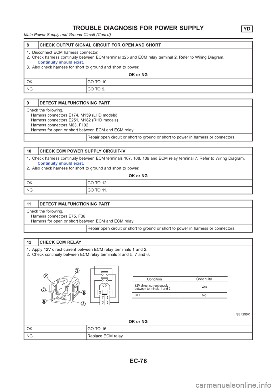
1. Apply 12V direct current between ECM relay terminals 1 and 2.
2. Check continuity between ECM relay terminals 3 and 5, 7 and 6.
SEF296X
OK or NG
OK GO TO 16.
NG Replace ECM relay.
TROUBLE DIAGNOSIS FOR POWER SUPPLYYD
Main Power Supply and Ground Circuit (Cont’d)
EC-76
Page 1131 of 3189
13 CHECK ECM POWER SUPPLY CIRCUIT-V
1. Turn ignition switch “OFF”.
2. Disconnect ECM relay. (For ECM relay location, refer to “Engine ControlComponent Parts Location”.)
3. Disconnect ECM harness connector.
4. Check harness continuity between ECM terminals 107, 108, 109 and ECM relay terminal 7. Refer to Wiring Diagram.
Continuity should exist.
5. Also check harness for short to ground and short to power.
OK or NG
OK GO TO 15.
NG GO TO 14.
14 DETECT MALFUNCTIONING PART
Check the following.
Harness connectors E75, F36
Harness for open or short between ECM and ECM relay
Repair open circuit or short to ground or short to power in harness or connectors.
15 CHECK ECM GROUND CIRCUIT FOR OPEN AND SHORT
1. Check harness continuity between ECM terminals 104, 105, 106 and engineground. Refer to Wiring Diagram.
Continuity should exist.
2. Also check harness for short to ground and short to power.
OK or NG
OK GO TO 16.
NG Repair open circuit or short to ground or short to power in harness or connectors.
16 CHECK INTERMITTENT INCIDENT
Refer to “TROUBLE DIAGNOSIS FOR INTERMITTENT INCIDENT”, EC-71.
INSPECTION END
GI
MA
EM
LC
FE
CL
MT
AT
AX
SU
BR
ST
RS
BT
HA
SC
EL
IDX
TROUBLE DIAGNOSIS FOR POWER SUPPLYYD
Main Power Supply and Ground Circuit (Cont’d)
EC-77
Page 1135 of 3189
Diagnostic ProcedureNJEC0648
1 CHECK MAFS POWER SUPPLY CIRCUIT
1. Turn ignition switch “OFF”.
2. Disconnect mass air flow sensor harness connector.
SEF884Y
3. Turn ignition switch “ON”.
4. Check voltage between mass air flow sensor terminals 2, 4 and ground withCONSULT-II or tester.
SEF297X
OK or NG
OK GO TO 3.
NG GO TO 2.
2 DETECT MALFUNCTIONING PART
Check the following.
Harness connectors E75, F36
Harness for open or short between mass air flow sensor and ECM
Harness for open or short between mass air flow sensor and ECM relay
Repair open circuit or short to ground or short to power in harness or connector.
GI
MA
EM
LC
FE
CL
MT
AT
AX
SU
BR
ST
RS
BT
HA
SC
EL
IDX
DTC P0100 MASS AIR FLOW SENYD
Diagnostic Procedure
EC-81
Page 1168 of 3189
7 CHECK BRAKE PEDAL POSITION SWITCH POWER SUPPLY CIRCUIT
1. Turn ignition switch “OFF”.
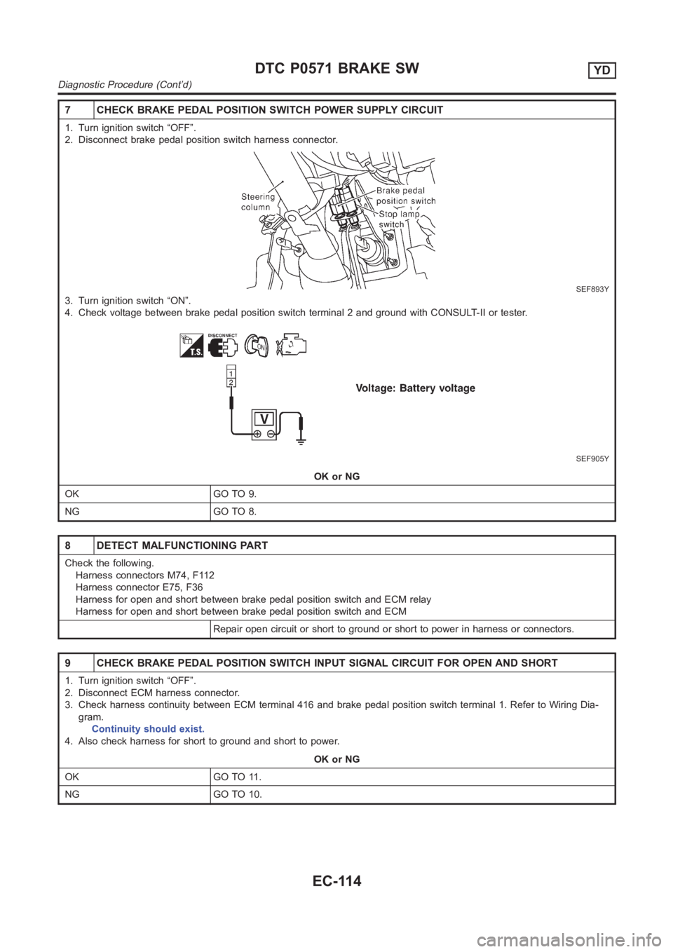
2. Disconnect brake pedal position switch harness connector.
SEF893Y
3. Turn ignition switch “ON”.
4. Check voltage between brake pedal position switch terminal 2 and groundwith CONSULT-II or tester.
SEF905Y
OK or NG
OK GO TO 9.
NG GO TO 8.
8 DETECT MALFUNCTIONING PART
Check the following.
Harness connectors M74, F112
Harness connector E75, F36
Harness for open and short between brake pedal position switch and ECM relay
Harness for open and short between brake pedal position switch and ECM
Repair open circuit or short to ground or short to power in harness or connectors.
9 CHECK BRAKE PEDAL POSITION SWITCH INPUT SIGNAL CIRCUIT FOR OPEN AND SHORT
1. Turn ignition switch “OFF”.
2. Disconnect ECM harness connector.
3. Check harness continuity between ECM terminal 416 and brake pedal position switch terminal 1. Refer to Wiring Dia-
gram.
Continuity should exist.
4. Also check harness for short to ground and short to power.
OK or NG
OK GO TO 11.
NG GO TO 10.
DTC P0571 BRAKE SWYD
Diagnostic Procedure (Cont’d)
EC-114
Page 1176 of 3189
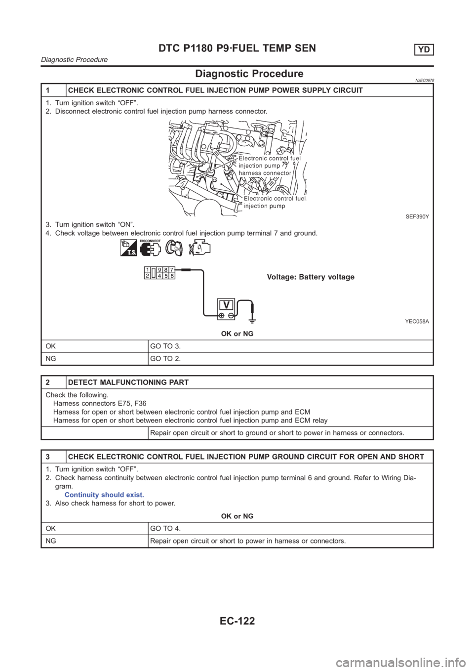
Diagnostic ProcedureNJEC0678
1 CHECK ELECTRONIC CONTROL FUEL INJECTION PUMP POWER SUPPLY CIRCUIT
1. Turn ignition switch “OFF”.
2. Disconnect electronic control fuel injection pump harness connector.
SEF390Y
3. Turn ignition switch “ON”.
4. Check voltage between electronic control fuel injection pump terminal7 and ground.
YEC058A
OK or NG
OK GO TO 3.
NG GO TO 2.
2 DETECT MALFUNCTIONING PART
Check the following.
Harness connectors E75, F36
Harness for open or short between electronic control fuel injection pump and ECM
Harness for open or short between electronic control fuel injection pump and ECM relay
Repair open circuit or short to ground or short to power in harness or connectors.
3 CHECK ELECTRONIC CONTROL FUEL INJECTION PUMP GROUND CIRCUIT FOR OPEN ANDSHORT
1. Turn ignition switch “OFF”.
2. Check harness continuity between electronic control fuel injection pump terminal 6 and ground. Refer to Wiring Dia-
gram.
Continuity should exist.
3. Also check harness for short to power.
OK or NG
OK GO TO 4.
NG Repair open circuit or short to power in harness or connectors.
DTC P1180 P9·FUEL TEMP SENYD
Diagnostic Procedure
EC-122
Page 1182 of 3189
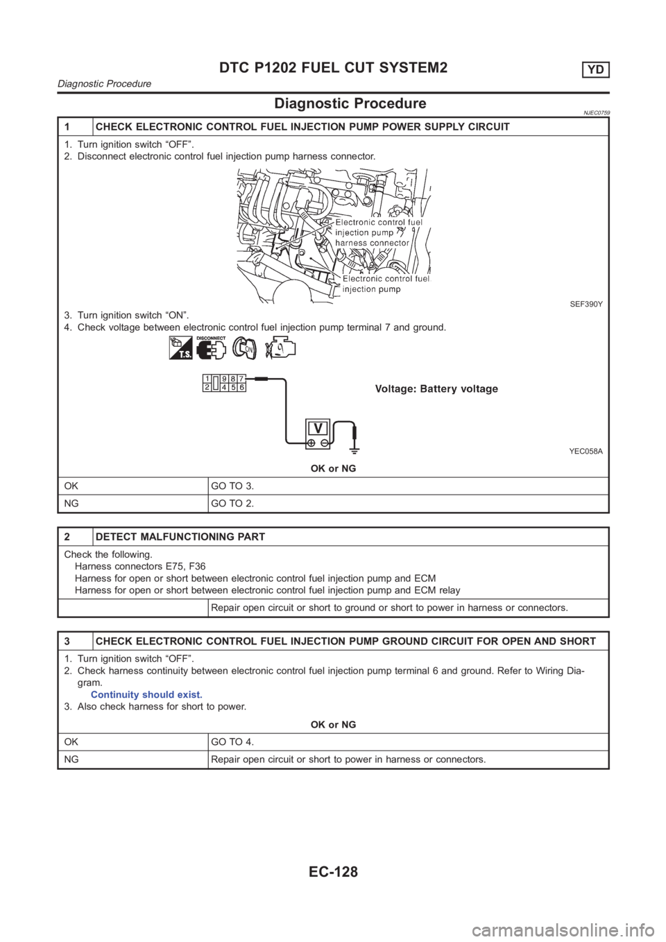
Diagnostic ProcedureNJEC0759
1 CHECK ELECTRONIC CONTROL FUEL INJECTION PUMP POWER SUPPLY CIRCUIT
1. Turn ignition switch “OFF”.
2. Disconnect electronic control fuel injection pump harness connector.
SEF390Y
3. Turn ignition switch “ON”.
4. Check voltage between electronic control fuel injection pump terminal7 and ground.
YEC058A
OK or NG
OK GO TO 3.
NG GO TO 2.
2 DETECT MALFUNCTIONING PART
Check the following.
Harness connectors E75, F36
Harness for open or short between electronic control fuel injection pump and ECM
Harness for open or short between electronic control fuel injection pump and ECM relay
Repair open circuit or short to ground or short to power in harness or connectors.
3 CHECK ELECTRONIC CONTROL FUEL INJECTION PUMP GROUND CIRCUIT FOR OPEN ANDSHORT
1. Turn ignition switch “OFF”.
2. Check harness continuity between electronic control fuel injection pump terminal 6 and ground. Refer to Wiring Dia-
gram.
Continuity should exist.
3. Also check harness for short to power.
OK or NG
OK GO TO 4.
NG Repair open circuit or short to power in harness or connectors.
DTC P1202 FUEL CUT SYSTEM2YD
Diagnostic Procedure
EC-128
Page 1184 of 3189
DescriptionNJEC0660SYSTEM DESCRIPTIONNJEC0660S01
Sensor Input signal to ECM ECM function Actuator
Vehicle speed sensor Vehicle speed
Cooling fan
controlCooling fan relay Engine coolant temperature sensor Engine coolant temperature
Air conditioner switch Air conditioner “ON” signal
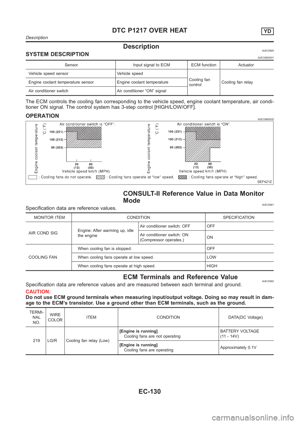
The ECM controls the cooling fan corresponding to the vehicle speed, engine coolant temperature, air condi-
tioner ON signal. The control system has 3-step control [HIGH/LOW/OFF].
OPERATIONNJEC0660S02
SEF421Z
CONSULT-II Reference Value in Data Monitor
Mode
NJEC0661Specification data are reference values.
MONITOR ITEM CONDITION SPECIFICATION
AIRCONDSIGEngine: After warming up, idle
the engineAir conditioner switch: OFF OFF
Air conditioner switch: ON
(Compressor operates.)ON
COOLING FANWhen cooling fan is stopped. OFF
When cooling fans operate at low speed. LOW
When cooling fans operate at high speed. HIGH
ECM Terminals and Reference ValueNJEC0662Specification data are reference values and are measured between each terminal and ground.
CAUTION:
Do not use ECM ground terminals when measuring input/output voltage. Doing so may result in dam-
age to the ECM’s transistor. Use a ground other than ECM terminals, such as the ground.
TERMI-
NAL
NO.WIRE
COLORITEM CONDITION DATA(DC Voltage)
219 LG/R Cooling fan relay (Low)[Engine is running]
Cooling fans are not operatingBATTERY VOLTAGE
(11 - 14V)
[Engine is running]
Cooling fans are operatingApproximately 0.1V
DTC P1217 OVER HEATYD
Description
EC-130