2003 NISSAN ALMERA N16 relay
[x] Cancel search: relayPage 2525 of 3189
SEL970W
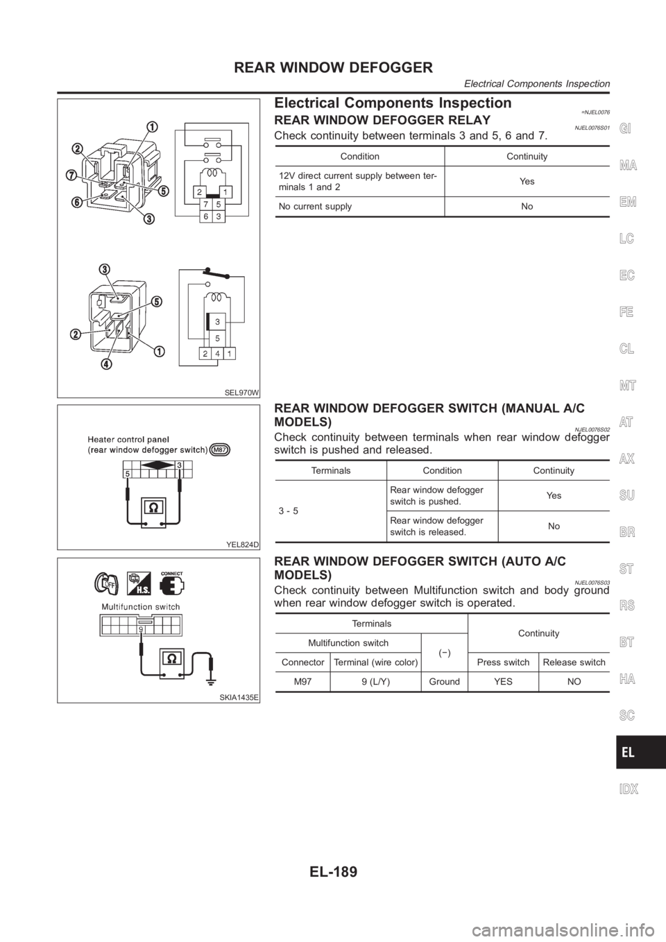
Electrical Components Inspection=NJEL0076REAR WINDOW DEFOGGER RELAYNJEL0076S01Check continuity between terminals 3 and 5, 6 and 7.
Condition Continuity
12V direct current supply between ter-
minals 1 and 2Ye s
No current supply No
YEL824D
REAR WINDOW DEFOGGER SWITCH (MANUAL A/C
MODELS)
NJEL0076S02Check continuity between terminals when rear window defogger
switch is pushed and released.
Terminals Condition Continuity
3-5Rear window defogger
switch is pushed.Ye s
Rear window defogger
switch is released.No
SKIA1435E
REAR WINDOW DEFOGGER SWITCH (AUTO A/C
MODELS)
NJEL0076S03Check continuity between Multifunction switch and body ground
when rear window defogger switch is operated.
Terminals
Continuity
Multifunction switch
(−)
Connector Terminal (wire color) Press switch Release switch
M97 9 (L/Y) Ground YES NO
GI
MA
EM
LC
EC
FE
CL
MT
AT
AX
SU
BR
ST
RS
BT
HA
SC
IDX
REAR WINDOW DEFOGGER
Electrical Components Inspection
EL-189
Page 2589 of 3189
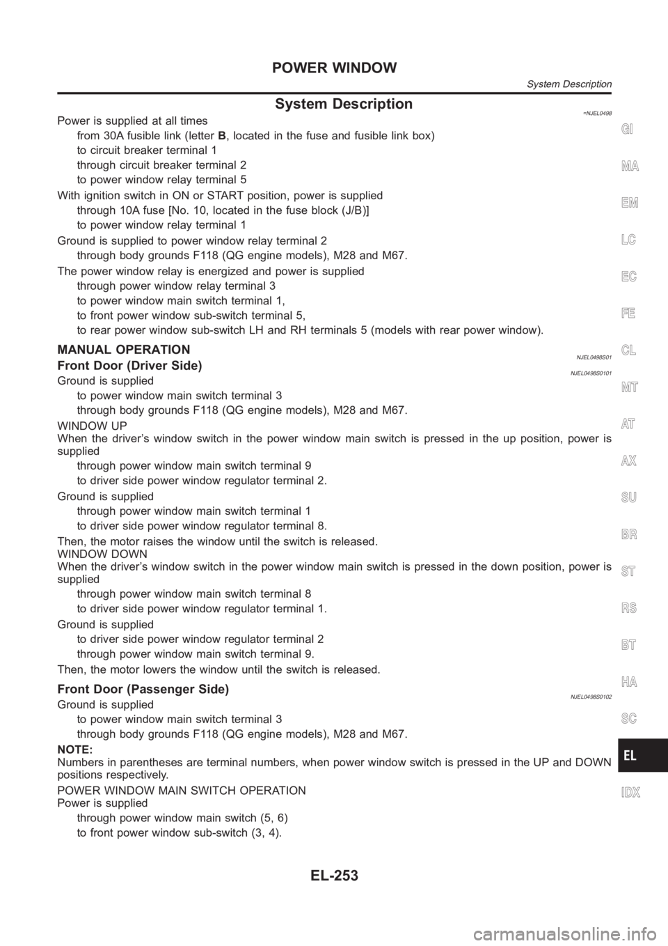
System Description=NJEL0498Power is supplied at all times
from 30A fusible link (letterB, located in the fuse and fusible link box)
to circuit breaker terminal 1
through circuit breaker terminal 2
to power window relay terminal 5
With ignition switch in ON or START position, power is supplied
through 10A fuse [No. 10, located in the fuse block (J/B)]
to power window relay terminal 1
Ground is supplied to power window relay terminal 2
through body grounds F118 (QG engine models), M28 and M67.
The power window relay is energized and power is supplied
through power window relay terminal 3
to power window main switch terminal 1,
to front power window sub-switch terminal 5,
to rear power window sub-switch LH and RH terminals 5 (models with rear power window).
MANUAL OPERATIONNJEL0498S01Front Door (Driver Side)NJEL0498S0101Ground is supplied
to power window main switch terminal 3
through body grounds F118 (QG engine models), M28 and M67.
WINDOW UP
When the driver’s window switch in the power window main switch is pressed in the up position, power is
supplied
through power window main switch terminal 9
to driver side power window regulator terminal 2.
Ground is supplied
through power window main switch terminal 1
to driver side power window regulator terminal 8.
Then, the motor raises the window until the switch is released.
WINDOW DOWN
When the driver’s window switch in the power window main switch is pressed in the down position, power is
supplied
through power window main switch terminal 8
to driver side power window regulator terminal 1.
Ground is supplied
to driver side power window regulator terminal 2
through power window main switch terminal 9.
Then, the motor lowers the window until the switch is released.
Front Door (Passenger Side)NJEL0498S0102Ground is supplied
to power window main switch terminal 3
through body grounds F118 (QG engine models), M28 and M67.
NOTE:
Numbers in parentheses are terminal numbers, when power window switch is pressed in the UP and DOWN
positions respectively.
POWER WINDOW MAIN SWITCH OPERATION
Power is supplied
through power window main switch (5, 6)
to front power window sub-switch (3, 4).
GI
MA
EM
LC
EC
FE
CL
MT
AT
AX
SU
BR
ST
RS
BT
HA
SC
IDX
POWER WINDOW
System Description
EL-253
Page 2596 of 3189
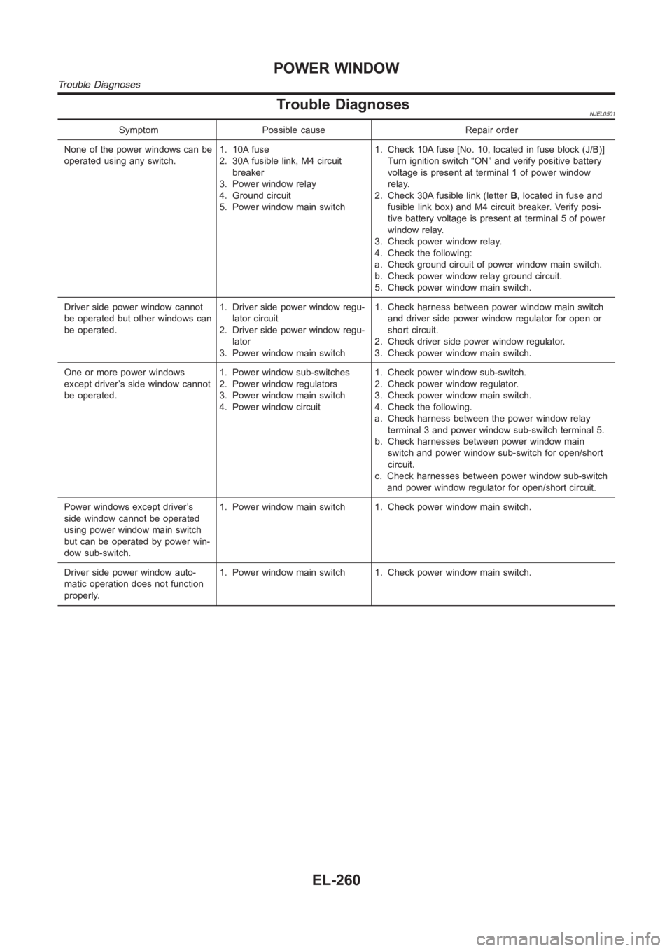
Trouble DiagnosesNJEL0501
Symptom Possible cause Repair order
None of the power windows can be
operated using any switch.1. 10A fuse
2. 30A fusible link, M4 circuit
breaker
3. Power window relay
4. Ground circuit
5. Power window main switch1. Check 10A fuse [No. 10, located in fuse block (J/B)]
Turn ignition switch “ON” and verify positive battery
voltage is present at terminal 1 of power window
relay.
2. Check 30A fusible link (letterB, located in fuse and
fusible link box) and M4 circuit breaker. Verify posi-
tive battery voltage is present at terminal 5 of power
window relay.
3. Check power window relay.
4. Check the following:
a. Check ground circuit of power window main switch.
b. Check power window relay ground circuit.
5. Check power window main switch.
Driver side power window cannot
be operated but other windows can
be operated.1. Driver side power window regu-
lator circuit
2. Driver side power window regu-
lator
3. Power window main switch1. Check harness between power window main switch
and driver side power window regulator for open or
short circuit.
2. Check driver side power window regulator.
3. Check power window main switch.
One or more power windows
except driver’s side window cannot
be operated.1. Power window sub-switches
2. Power window regulators
3. Power window main switch
4. Power window circuit1. Check power window sub-switch.
2. Check power window regulator.
3. Check power window main switch.
4. Check the following.
a. Check harness between the power window relay
terminal 3 and power window sub-switch terminal 5.
b. Check harnesses between power window main
switch and power window sub-switch for open/short
circuit.
c. Check harnesses between power window sub-switch
and power window regulator for open/short circuit.
Power windows except driver’s
side window cannot be operated
using power window main switch
but can be operated by power win-
dow sub-switch.1. Power window main switch 1. Check power window main switch.
Driver side power window auto-
matic operation does not function
properly.1. Power window main switch 1. Check power window main switch.
POWER WINDOW
Trouble Diagnoses
EL-260
Page 2705 of 3189
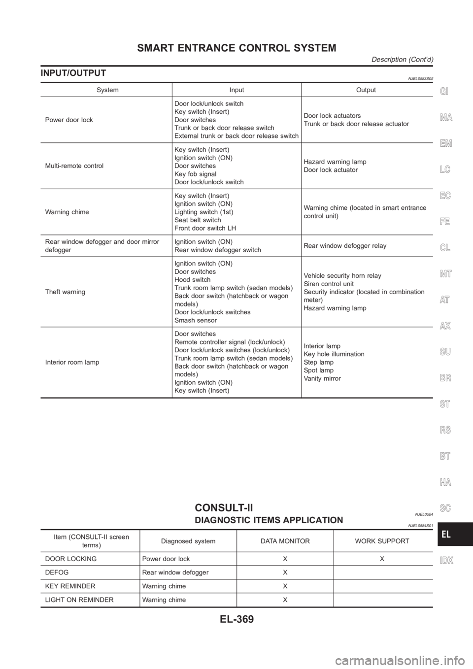
INPUT/OUTPUTNJEL0583S05
System Input Output
Power door lockDoor lock/unlock switch
Key switch (Insert)
Door switches
Trunk or back door release switch
External trunk or back door release switchDoor lock actuators
Trunk or back door release actuator
Multi-remote controlKey switch (Insert)
Ignition switch (ON)
Door switches
Key fob signal
Door lock/unlock switchHazard warning lamp
Door lock actuator
Warning chimeKey switch (Insert)
Ignition switch (ON)
Lighting switch (1st)
Seat belt switch
Front door switch LHWarning chime (located in smart entrance
control unit)
Rear window defogger and door mirror
defoggerIgnition switch (ON)
Rear window defogger switchRear window defogger relay
Theft warningIgnition switch (ON)
Door switches
Hood switch
Trunk room lamp switch (sedan models)
Back door switch (hatchback or wagon
models)
Door lock/unlock switches
Smash sensorVehicle security horn relay
Siren control unit
Security indicator (located in combination
meter)
Hazard warning lamp
Interior room lampDoor switches
Remote controller signal (lock/unlock)
Door lock/unlock switches (lock/unlock)
Trunk room lamp switch (sedan models)
Back door switch (hatchback or wagon
models)
Ignition switch (ON)
Key switch (Insert)Interior lamp
Key hole illumination
Step lamp
Spot lamp
Vanity mirror
CONSULT-IINJEL0584DIAGNOSTIC ITEMS APPLICATIONNJEL0584S01
Item (CONSULT-II screen
terms)Diagnosed system DATA MONITOR WORK SUPPORT
DOOR LOCKING Power door lock X X
DEFOG Rear window defogger X
KEY REMINDER Warning chime X
LIGHT ON REMINDER Warning chime X
GI
MA
EM
LC
EC
FE
CL
MT
AT
AX
SU
BR
ST
RS
BT
HA
SC
IDX
SMART ENTRANCE CONTROL SYSTEM
Description (Cont’d)
EL-369
Page 2713 of 3189
![NISSAN ALMERA N16 2003 Electronic Repair Manual Terminal
No.Wire
colorConnections Operated condition Voltage (Approximate values)
24 BRWasher switch
(Headlamp washer switch)[Head lamp switch 1st or 2nd posi-
tion]
Washer switch OFF,ON12V,0V
25 G/OR NISSAN ALMERA N16 2003 Electronic Repair Manual Terminal
No.Wire
colorConnections Operated condition Voltage (Approximate values)
24 BRWasher switch
(Headlamp washer switch)[Head lamp switch 1st or 2nd posi-
tion]
Washer switch OFF,ON12V,0V
25 G/OR](/manual-img/5/57350/w960_57350-2712.png)
Terminal
No.Wire
colorConnections Operated condition Voltage (Approximate values)
24 BRWasher switch
(Headlamp washer switch)[Head lamp switch 1st or 2nd posi-
tion]
Washer switch OFF,ON12V,0V
25 G/ORCombination switch
(Turn signal switch)Turn signal switch:
Neutral,Left turn position12V,0V
26 L/BCombination switch
(Turn signal switch)Turn signal switch:
Neutral,Right turn position12V,0V
27 Y/BVehicle security horn relay
(RHD models)When theft warning system:
Armed,Disarmed0V,12V
28 R/Y Interior room lampWhen interior lamp is operated using
remote controller (Lamp switch in
“DOOR” position)12V,0V
29 Y/G Ignition key switch Ignition key is in “ON” position 12V
30 G/R Hazard switch Hazard switch: OFF,ON 12V,0V
31 W Rear window defogger relay[Ignition switch “ON”]
Rear window defogger switch:
OFF,ON12V,0V
32 LG/B Cooling fan relay[Ignition switch“ ON”]
Cooling fan: Operating,Not operat-
ing0V,12V
33 LG/R Cooling fan relay[Ignition switch “ON”]
Cooling fan: Operating,Not operat-
ing0V,12V
34 L/Y Security indicator Ignition switch ON,OFF 12V,0V
39 BR/WRear door switch
(Passenger side)Rear door LH or RH: Open,Closed 0V,12V
41 L Air conditioner relay[Engine is running]
Air conditioner switch: ON,
OFF12V,0V
43 R/WFront door switch
(Driver side)Front door (Driver side):
Open,Closed12V,0V
44 R/WFront door switch
(Passenger side)Front door (Passenger side):
Open,Closed0V,12V
45 R/YRear door switch
(Driver side)Rear door LH or RH: Open,Closed 0V,12V
49 W/L Power source — 12V
50 GPower door super lock actuator
(Rear)Remote controller door lock switch:
Free,Press0V,12V
51 L/R Driver door lock actuatorDoor lock & unlock switch:
Free,Lock0V,12V
52 W/R Door lock actuatorsDoor lock & unlock switch:
Free,Unlock0V,12V
53 B Ground — 0V
54 R/B Door lock actuatorsDoor lock & unlock switch:
Free,Unlock0V,12V
55 W/BPower door super lock actuator
(Front)Remote controller door lock switch:
Free,Unlock0V,12V
56 R/B Power source — 12V
GI
MA
EM
LC
EC
FE
CL
MT
AT
AX
SU
BR
ST
RS
BT
HA
SC
IDX
SMART ENTRANCE CONTROL SYSTEM
Smart Entrance Control Unit Inspection Table (Cont’d)
EL-377
Page 2746 of 3189
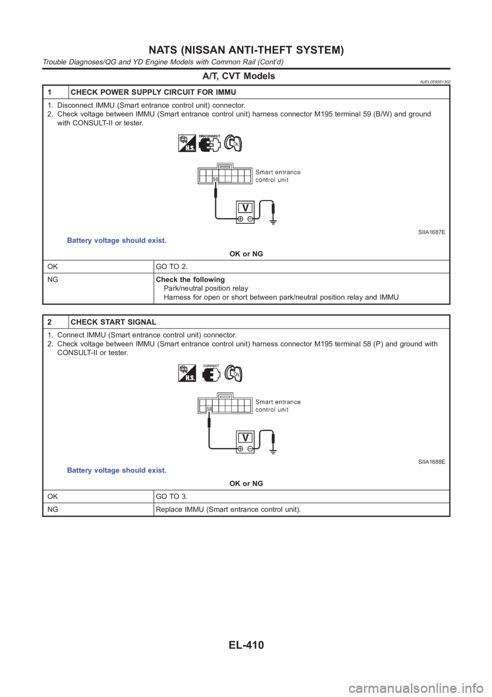
A/T, CVT ModelsNJEL0590S1302
1 CHECK POWER SUPPLY CIRCUIT FOR IMMU
1. Disconnect IMMU (Smart entrance control unit) connector.
2. Check voltage between IMMU (Smart entrance control unit) harness connector M195 terminal 59 (B/W) and ground
with CONSULT-II or tester.
SIIA1687E
Battery voltage should exist.
OK or NG
OK GO TO 2.
NGCheck the following
Park/neutral position relay
Harness for open or short between park/neutral position relay and IMMU
2 CHECK START SIGNAL
1. Connect IMMU (Smart entrance control unit) connector.
2. Check voltage between IMMU (Smart entrance control unit) harness connector M195 terminal 58 (P) and ground with
CONSULT-II or tester.
SIIA1688E
Battery voltage should exist.
OK or NG
OK GO TO 3.
NG Replace IMMU (Smart entrance control unit).
NATS (NISSAN ANTI-THEFT SYSTEM)
Trouble Diagnoses/QG and YD Engine Models with Common Rail (Cont’d)
EL-410
Page 2810 of 3189
Reverse Signal Check=NJEL0610
1 REVERSE LAMP CHECK
1. Turn the ignition switch ON.
2. A/T Shift selector lever into R-position. Does “R” in the shift positionindicator come on?
YesorNo
Ye s G O T O 2 .
No Check park/neutral position relay system. AT-408, “Park/Neutral Position (PNP) Switch
Adjustment”.
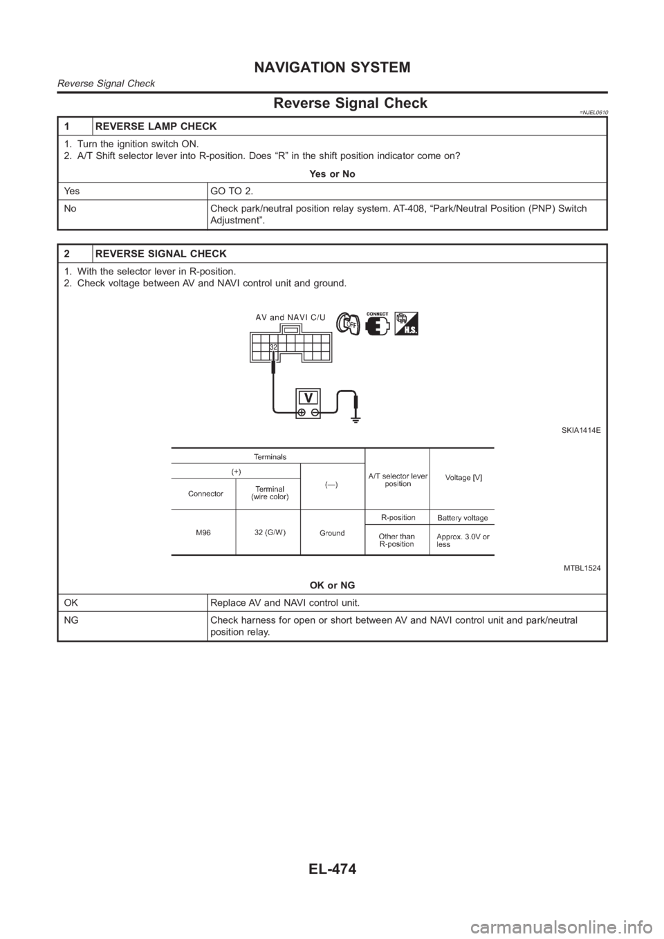
2 REVERSE SIGNAL CHECK
1. With the selector lever in R-position.
2. Check voltage between AV and NAVI control unit and ground.
SKIA1414E
MTBL1524
OK or NG
OK Replace AV and NAVI control unit.
NG Check harness for open or short between AV and NAVI control unit and park/neutral
position relay.
NAVIGATION SYSTEM
Reverse Signal Check
EL-474
Page 2828 of 3189
Rear Defogger Indicator Lamp Does Not
Illuminate
NJEL0619
1 CHECK POSITION OF IGNITION SWITCH
Is ignition switch ON?
YesorNo
Ye s G O T O 2 .
No Rear defogger does not operate if ignition switch is not ON.
2 CHECK OPERATION OF REAR DEFOGGER
Does rear defogger operate when rear defogger switch is turned ON? (Does fogging disappear?)
YesorNo
Ye s G O T O 3 .
No Check rear defogger system. Refer to EL-183, “Rear Defogger Does Not Operate”.
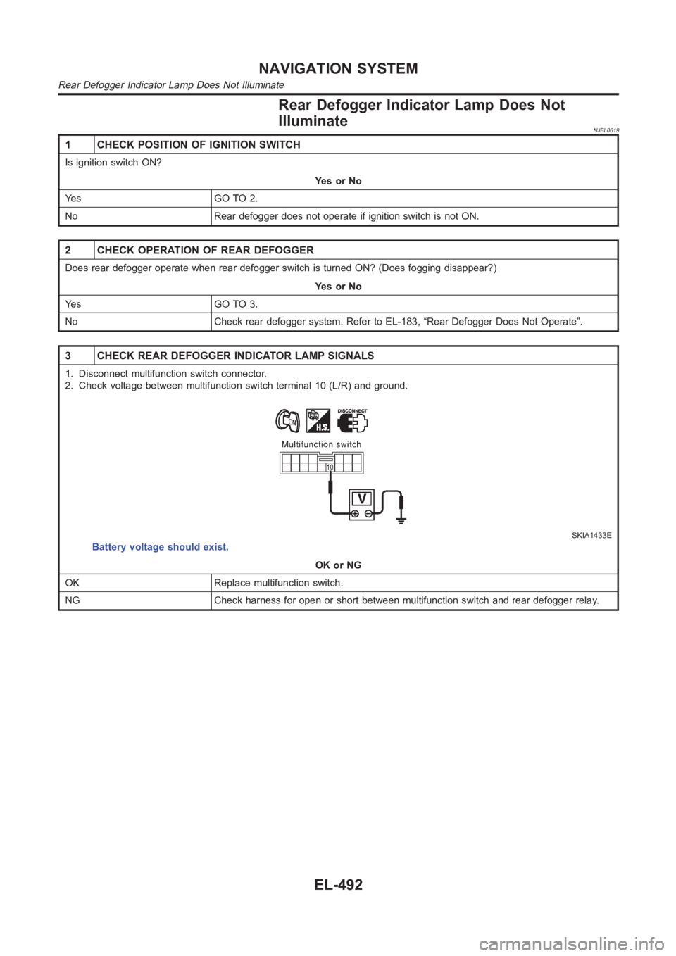
3 CHECK REAR DEFOGGER INDICATOR LAMP SIGNALS
1. Disconnect multifunction switch connector.
2. Check voltage between multifunction switch terminal 10 (L/R) and ground.
SKIA1433E
Battery voltage should exist.
OK or NG
OK Replace multifunction switch.
NG Check harness for open or short between multifunction switch and rear defogger relay.
NAVIGATION SYSTEM
Rear Defogger Indicator Lamp Does Not Illuminate
EL-492