Page 2886 of 3189
How to Read Harness LayoutNJEL0131
SEL252V
The following Harness Layouts use a map style grid to help locate connectors on the drawings:
Main Harness
Engine Room Harness (Engine Compartment)
Engine Control Harness
Body Harness
TO USE THE GRID REFERENCENJEL0131S011. Find the desired connector number on the connector list.
2. Find the grid reference.
3. On the drawing, find the crossing of the grid reference letter column andnumber row.
4. Find the connector number in the crossing zone.
5. Follow the line (if used) to the connector.
CONNECTOR SYMBOLNJEL0131S02Main symbols of connector (in Harness Layout) are indicated in the below.
Connector typeWater proof type Standard type
Male Female Male Female
Cavity: Less than 4
Relay connector
Cavity: From 5 to 8
Cavity: More than 9
Ground terminal etc.
—
HARNESS LAYOUT
How to Read Harness Layout
EL-550
Page 2935 of 3189

NJEL0311
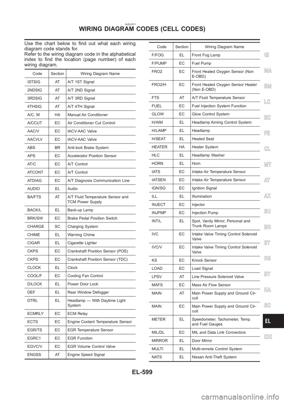
Use the chart below to find out what each wiring
diagram code stands for.
Refer to the wiring diagram code in the alphabetical
index to find the location (page number) of each
wiring diagram.
Code Section Wiring Diagram Name
ISTSIG AT A/T 1ST Signal
2NDSIG AT A/T 2ND Signal
3RDSIG AT A/T 3RD Signal
4THSIG AT A/T 4TH Signal
A/C, M HA Manual Air Conditioner
A/CCUT EC Air Conditioner Cut Control
AAC/V EC IACV-AAC Valve
AACVLV EC IACV-AAC Valve
ABS BR Anti-lock Brake System
APS EC Accelerator Position Sensor
AT/C EC A/T Control
ATCONT EC A/T Control
ATDIAG EC A/T Diagnosis Communication Line
AUDIO EL Audio
BA/FTS AT A/T Fluid Temperature Sensor and
TCM Power Supply
BACK/L EL Back-up Lamp
BRK/SW EC Brake Pedal Position Switch
CHARGE SC Charging System
CHIME EL Warning Chime
CIGAR EL Cigarette Lighter
CKPS EC Crankshaft Position Sensor (POS)
CKPS EC Crankshaft Position Sensor (TDC)
CLOCK EL Clock
COOL/F EC Cooling Fan Control
D/LOCK EL Power Door Lock
DEF EL Rear Window Defogger
DTRL EL Headlamp — With Daytime Light
System
ECMRLY EC ECM Relay
ECTS EC Engine Coolant Temperature Sensor
EGR/TS EC EGR Temperature Sensor
EGRC1 EC EGR Function
EGVC/V EC EGR Volume Control Valve
ENGSS AT Engine Speed Signal
Code Section Wiring Diagram Name
F/FOG EL Front Fog Lamp
F/PUMP EC Fuel Pump
FRO2 EC Front Heated Oxygen Sensor (Non
E-OBD)
FRO2/H EC Front Heated Oxygen Sensor Heater
(Non E-OBD)
FTS AT A/T Fluid Temperature Sensor
FUEL EC Fuel Injection System Function
GLOW EC Glow Control System
H/AIM EL Headlamp Aiming Control System
H/LAMP EL Headlamp
H/SEAT EL Heated Seat
HEATER HA Heater System
HLC EL Headlamp Washer
HORN EL Horn
IATS EC Intake Air Temperature Sensor
IATSEN EC Intake Air Temperature Sensor
IGN/SG EC Ignition Signal
ILL EL Illumination
INJECT EC Injector
INJPMP EC Injection Pump
INT/L EL Spot, Vanity Mirror, Personal and
Trunk Room Lamps
IVC EC Intake Valve Timing Control Solenoid
Valve
IVC/V EC Intake Valve Timing Control Solenoid
Valve
KS EC Knock Sensor
LOAD EC Load Signal
LPSV AT Line Pressure Solenoid Valve
MAFS EC Mass Air Flow Sensor
MAIN AT Main Power Supply and Ground Cir-
cuit
MAIN EC Main Power Supply and Ground Cir-
cuit
METER EL Speedometer, Tachometer, Temp.
and Fuel Gauges
MIL/DL EC MIL and Data Link Connectors
MIRROR EL Door Mirror
MULTI EL Multi-remote Control System
NATS EL Nissan Anti-Theft System
GI
MA
EM
LC
EC
FE
CL
MT
AT
AX
SU
BR
ST
RS
BT
HA
SC
IDX
WIRING DIAGRAM CODES (CELL CODES)
EL-599
Page 2948 of 3189

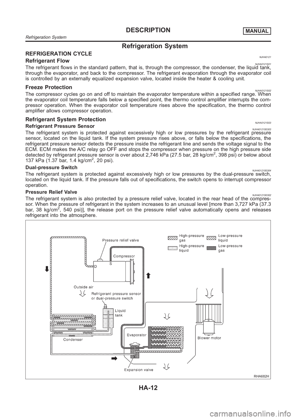
Refrigeration System
REFRIGERATION CYCLENJHA0121Refrigerant FlowNJHA0121S01The refrigerant flows in the standard pattern, that is, through the compressor, the condenser, the liquid tank,
through the evaporator, and back to the compressor. The refrigerant evaporation through the evaporator coil
is controlled by an externally equalized expansion valve, located insidethe heater & cooling unit.
Freeze ProtectionNJHA0121S02The compressor cycles go on and off to maintain the evaporator temperaturewithin a specified range. When
the evaporator coil temperature falls below a specified point, the thermocontrol amplifier interrupts the com-
pressor operation. When the evaporator coil temperature rises above the specification, the thermo control
amplifier allows compressor operation.
Refrigerant System ProtectionNJHA0121S03Refrigerant Pressure SensorNJHA0121S0303The refrigerant system is protected against excessively high or low pressures by the refrigerant pressure
sensor, located on the liquid tank. If the system pressure rises above, or falls below the specifications, the
refrigerant pressure sensor detects the pressure inside the refrigerantline and sends the voltage signal to the
ECM. ECM makes the A/C relay go OFF and stops the compressor when pressure onthe high pressure side
detected by refrigerant pressure sensor is over about 2,746 kPa (27.5 bar,28 kg/cm
2, 398 psi) or below about
137 kPa (1.37 bar, 1.4 kg/cm2, 20 psi).
Dual-pressure Switch
NJHA0121S0304The refrigerant system is protected against excessively high or low pressures by the dual-pressure switch,
located on the liquid tank. If the pressure falls out of specifications, the switch opens to interrupt compressor
operation.
Pressure Relief Valve
NJHA0121S0302The refrigerant system is also protected by a pressure relief valve, located in the rear head of the compres-
sor. When the pressure of refrigerant in the system increases to an unusuallevel [more than 3,727 kPa (37.3
bar, 38 kg/cm
2, 540 psi)], the release port on the pressure relief valve automatically opens and releases
refrigerant into the atmosphere.
RHA682H
DESCRIPTIONMANUAL
Refrigeration System
HA-12
Page 2989 of 3189
MAGNET CLUTCH CIRCUIT (QG ENGINE AND YD
ENGINE WITH COMMON RAIL)
=NJHA0156SYMPTOM:
Magnet clutch does not engage when A/C switch and fan
switch are ON.
1 CHECK POWER SUPPLY FOR COMPRESSOR
Disconnect compressor harness connector.
Do approx. 12 volts exist between compressor harness terminal No. 1 and body ground?
RHA794H
YesorNo
Ye s G O T O 2 .
No Disconnect A/C relay. GO TO 3.
2 CHECK MAGNET CLUTCH COIL
Check for operation sound when applying battery voltage direct current toterminal.
RHA256I
OK or NG
NG Replace magnet clutch. Refer to HA-84.
GI
MA
EM
LC
EC
FE
CL
MT
AT
AX
SU
BR
ST
RS
BT
SC
EL
IDX
TROUBLE DIAGNOSESMANUAL
Magnet Clutch (Cont’d)
HA-53
Page 2990 of 3189
3 CHECK CIRCUIT CONTINUITY BETWEEN A/C RELAY AND COMPRESSOR HARNESS
Check circuit continuity between A/C relay harness terminal No. 3 and compressor harness terminal No. 1.
RHA634H
Continuity should exist.
If OK, check harness for short.
OK or NG
OK GO TO 4.
NG Repair harness or connector.
4 CHECK POWER SUPPLY FOR A/C RELAY
Disconnect A/C relay.
Do approx. 12 volts exist between A/C relay harness terminal Nos. 1, 5 and body ground?
RHA635H
YesorNo
Ye s G O T O 5 .
No Check power supply circuit and 10A (No. 15) fuse at fuse block. Refer to EL-14, “Wiring
Diagram — POWER —”.
5 CHECK A/C RELAY AFTER DISCONNECTING IT
Refer to HA-65.
OK or NG
OK Reconnect A/C relay. GO TO 6.
NG Replace A/C relay.
TROUBLE DIAGNOSESMANUAL
Magnet Clutch (Cont’d)
HA-54
Page 2991 of 3189
6 CHECK COIL SIDE CIRCUIT OF A/C RELAY
Do approx. 12 volts exist between smart entrance control unit harness terminal No. 41 and body ground?
RHA257I
YesorNo
Ye s G O T O 8 .
No Disconnect A/C relay. Disconnect smart entrance control unit harness connector. GO TO
7.
7 CHECK CIRCUIT CONTINUITY BETWEEN A/C RELAY AND SMART ENTRANCE CONTROL UNIT HAR-
NESS
Check circuit continuity between A/C relay harness terminal No. 2 and smart entrance control unit harness terminal No.
41.
RHA258I
Continuity should exist.
If OK, check harness for short.
OK or NG
OK Check smart entrance control unit. Refer to EL-368.
NG Repair harness or connector.
GI
MA
EM
LC
EC
FE
CL
MT
AT
AX
SU
BR
ST
RS
BT
SC
EL
IDX
TROUBLE DIAGNOSESMANUAL
Magnet Clutch (Cont’d)
HA-55
Page 2996 of 3189
20 CHECK CAN COMMUNICATION
Check CAN communication. Refer to EL-509.
Combination meter - Smart entrance control unit
Combination meter - ECM
ECM - Smart entrance control unit
OK or NG
OK INSPECTION END
NG Repair or replace malfunctioning part(s).
MAGNET CLUTCH CIRCUIT (YD ENGINE WITHOUT
COMMON RAIL)
NJHA0203SYMPTOM:
Magnet clutch does not engage when A/C switch and fan
switch are ON.
1 CHECK POWER SUPPLY FOR COMPRESSOR
Disconnect compressor harness connector.
Do approx. 12 volts exist between compressor harness terminal No. 1 and body ground?
RHA794H
YesorNo
Ye s G O T O 2 .
No Disconnect A/C relay. GO TO 3.
2 CHECK MAGNET CLUTCH COIL
Check for operation sound when applying battery voltage direct current toterminal.
RHA256I
OK or NG
NG Replace magnet clutch. Refer to HA-84.
TROUBLE DIAGNOSESMANUAL
Magnet Clutch (Cont’d)
HA-60
Page 2997 of 3189
3 CHECK CIRCUIT CONTINUITY BETWEEN A/C RELAY AND COMPRESSOR HARNESS
Check circuit continuity between A/C relay harness terminal No. 3 and compressor harness terminal No. 1.
RHA634H
Continuity should exist.
If OK, check harness for short.
OK or NG
OK GO TO 4.
NG Repair harness or connector.
4 CHECK POWER SUPPLY FOR A/C RELAY
Disconnect A/C relay.
Do approx. 12 volts exist between A/C relay harness terminal Nos. 1, 5 and body ground?
RHA635H
YesorNo
Ye s G O T O 5 .
No Check power supply circuit and 10A (No. 15) fuse at fuse block. Refer to EL-14, “Wiring
Diagram — POWER —”.
5 CHECK A/C RELAY AFTER DISCONNECTING IT
Refer to HA-65.
OK or NG
OK Reconnect A/C relay. GO TO 6.
NG Replace A/C relay.
GI
MA
EM
LC
EC
FE
CL
MT
AT
AX
SU
BR
ST
RS
BT
SC
EL
IDX
TROUBLE DIAGNOSESMANUAL
Magnet Clutch (Cont’d)
HA-61