Page 374 of 4500
INSPECTION PROCEDURE
1.PERFORM ACTUATOR CHECK
a. Warm up the engine.
b. Set the actuator check mode (SEE ACTUATOR CHECK
).
c. Press the driver temperature up switch, and change to STEP operation.
d. Press the driver temperature up switch, and check the operation of water valve.
Fig. 133: Checking Actuator
Courtesy of TOYOTA MOTOR SALES, U.S.A., INC.
DISPLAY CODE - AIR FLOW LEVER POSITION
Display codeAir flow lever position
0SHUT
1SHUT
2SHUT
3OPEN
4OPEN
5OPEN
6OPEN
Page 379 of 4500
Fig. 136: Air Vent Mode Damper Control Servomotor Circuit
Courtesy of TOYOTA MOTOR SALES, U.S.A., INC.
INSPECTION PROCEDURE
1.PERFORM ACTUATOR CHECK
a. Warm up the engine.
b. Set the actuator check mode (see ACTUATOR CHECK).
Page 390 of 4500

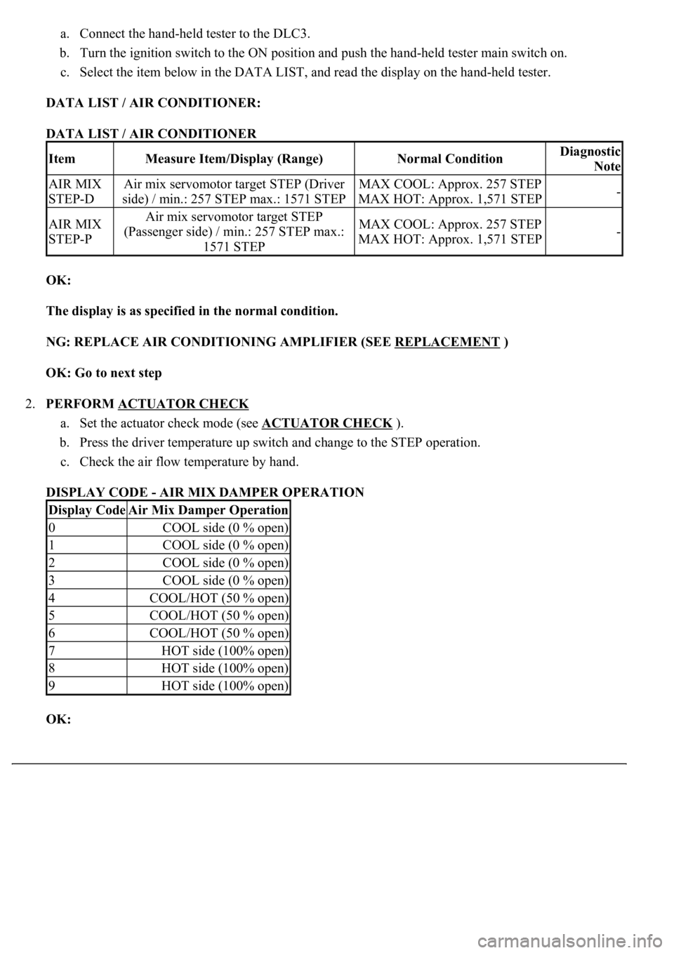
a. Connect the hand-held tester to the DLC3.
b. Turn the ignition switch to the ON position and push the hand-held tester main switch on.
c. Select the item below in the DATA LIST, and read the display on the hand-held tester.
DATA LIST / AIR CONDITIONER:
DATA LIST / AIR CONDITIONER
OK:
The display is as specified in the normal condition.
NG: REPLACE AIR CONDITIONING AMPLIFIER (SEE REPLACEMENT
)
OK: Go to next step
2.PERFORM ACTUATOR CHECK
a. Set the actuator check mode (see ACTUATOR CHECK
).
b. Press the driver temperature up switch and change to the STEP operation.
c. Check the air flow temperature by hand.
DISPLAY CODE - AIR MIX DAMPER OPERATION
OK:
ItemMeasure Item/Display (Range)Normal ConditionDiagnostic
Note
AIR MIX
STEP-DAir mix servomotor target STEP (Driver
side) / min.: 257 STEP max.: 1571 STEPMAX COOL: Approx. 257 STEP
MAX HOT: Approx. 1,571 STEP-
AIR MIX
STEP-PAir mix servomotor target STEP
(Passenger side) / min.: 257 STEP max.:
1571 STEPMAX COOL: Approx. 257 STEP
MAX HOT: Approx. 1,571 STEP-
Display CodeAir Mix Damper Operation
0COOL side (0 % open)
1COOL side (0 % open)
2COOL side (0 % open)
3COOL side (0 % open)
4COOL/HOT (50 % open)
5COOL/HOT (50 % open)
6COOL/HOT (50 % open)
7HOT side (100% open)
8HOT side (100% open)
9HOT side (100% open)
Page 413 of 4500

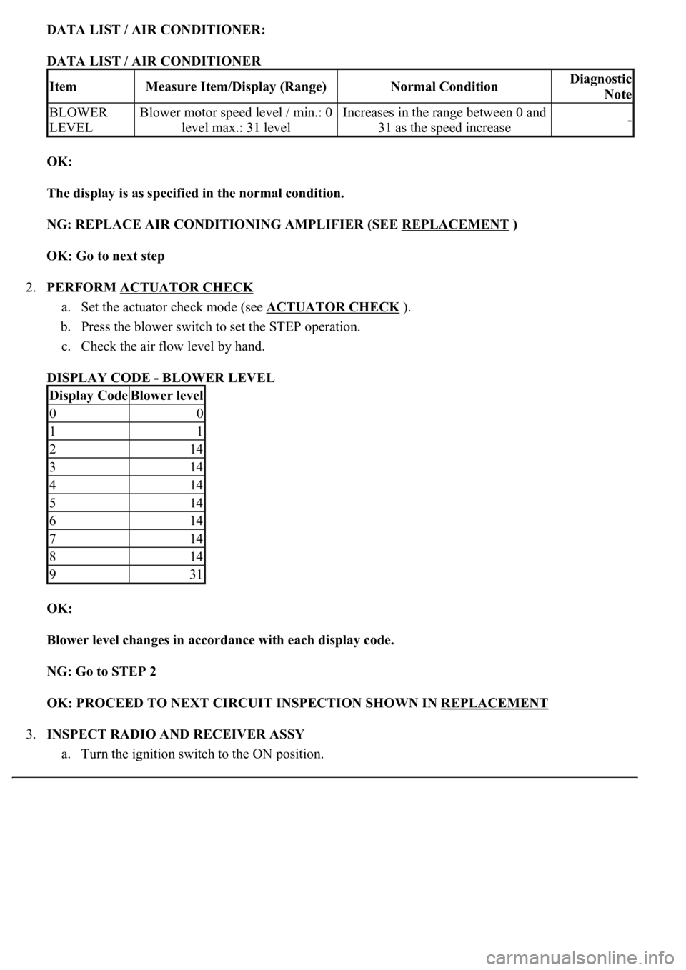
DATA LIST / AIR CONDITIONER:
DATA LIST / AIR CONDITIONER
OK:
The display is as specified in the normal condition.
NG: REPLACE AIR CONDITIONING AMPLIFIER (SEE REPLACEMENT
)
OK: Go to next step
2.PERFORM ACTUATOR CHECK
a. Set the actuator check mode (see ACTUATOR CHECK
).
b. Press the blower switch to set the STEP operation.
c. Check the air flow level by hand.
DISPLAY CODE - BLOWER LEVEL
OK:
<0025004f0052005a004800550003004f004800590048004f00030046004b00440051004a004800560003004c0051000300440046004600520055004700440051004600480003005a004c0057004b0003004800440046004b00030047004c00560053004f00
44005c000300460052004700480011[
NG: Go to STEP 2
OK: PROCEED TO NEXT CIRCUIT INSPECTION SHOWN IN REPLACEMENT
3.INSPECT RADIO AND RECEIVER ASSY
a. Turn the ignition switch to the ON position.
ItemMeasure Item/Display (Range)Normal ConditionDiagnostic
Note
BLOWER
LEVELBlower motor speed level / min.: 0
level max.: 31 levelIncreases in the range between 0 and
31 as the speed increase-
Display CodeBlower level
00
11
214
314
414
514
614
714
814
931
Page 444 of 4500

Courtesy of TOYOTA MOTOR SALES, U.S.A., INC.
INSPECTION PROCEDURE
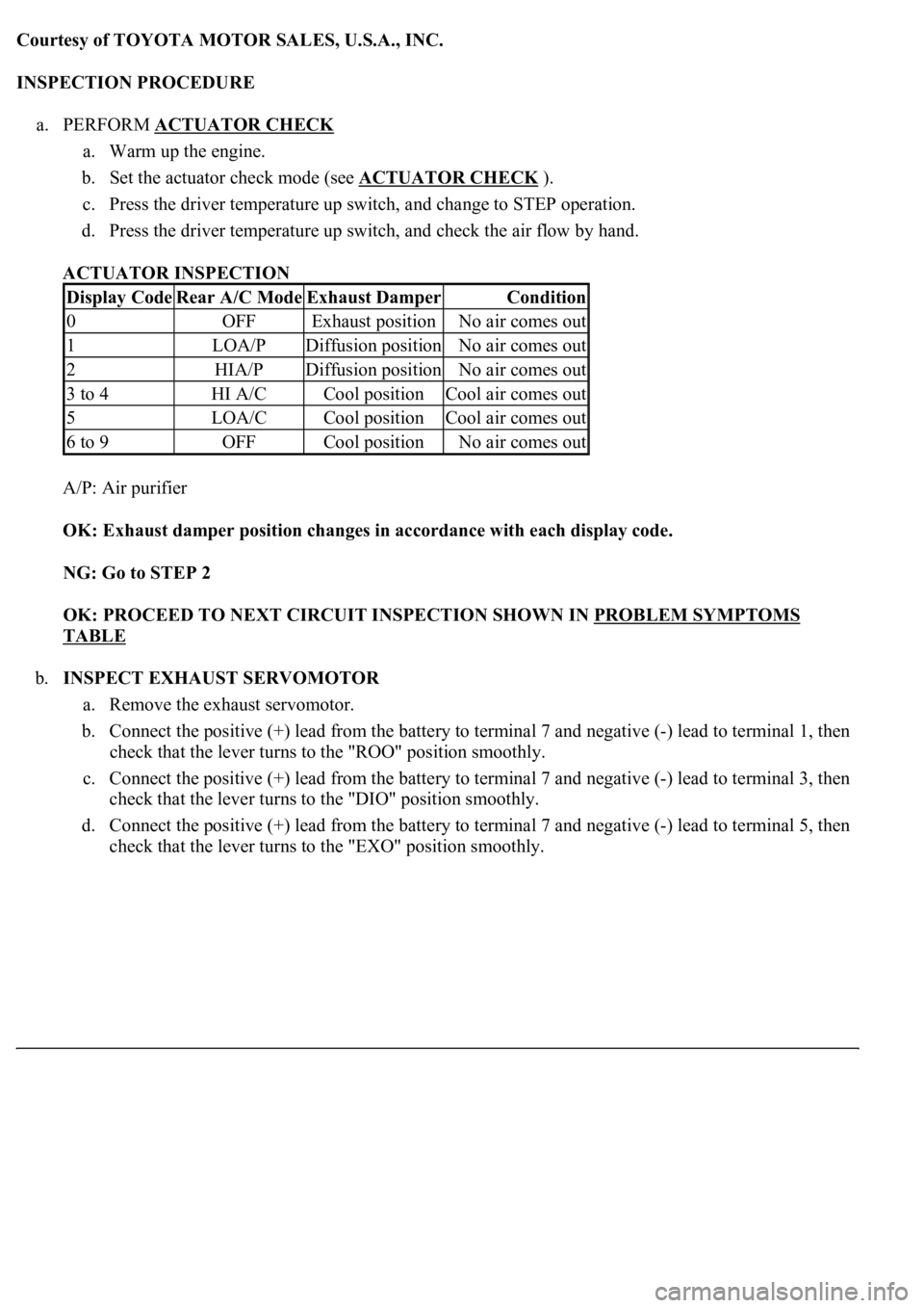
a. PERFORM ACTUATOR CHECK
a. Warm up the engine.
b. Set the actuator check mode (see ACTUATOR CHECK
).
c. Press the driver temperature up switch, and change to STEP operation.
d. Press the driver temperature up switch, and check the air flow by hand.
ACTUATOR INSPECTION
A/P: Air purifier
OK: Exhaust damper position changes in accordance with each display code.
NG: Go to STEP 2
OK: PROCEED TO NEXT CIRCUIT INSPECTION SHOWN IN PROBLEM SYMPTOMS
TABLE
b.INSPECT EXHAUST SERVOMOTOR
a. Remove the exhaust servomotor.
b. Connect the positive (+) lead from the battery to terminal 7 and negative (-) lead to terminal 1, then
check that the lever turns to the "ROO" position smoothly.
c. Connect the positive (+) lead from the battery to terminal 7 and negative (-) lead to terminal 3, then
check that the lever turns to the "DIO" position smoothly.
d. Connect the positive (+) lead from the battery to terminal 7 and negative (-) lead to terminal 5, then
check that the lever turns to the "EXO" position smoothl
y.
Display CodeRear A/C ModeExhaust DamperCondition
0OFFExhaust positionNo air comes out
1LOA/PDiffusion positionNo air comes out
2HIA/PDiffusion positionNo air comes out
3 to 4HI A/CCool positionCool air comes out
5LOA/CCool positionCool air comes out
6 to 9OFFCool positionNo air comes out
Page 481 of 4500

RC (A20-6) -
GND (A20-4)Y-R - W-BAIR SUS relay
Engine idling, height control switch
from "NORM" to "HIGH" during
compressor operation
8 V or more
CANH (A20-7) -
CANL (A20-8)BR - YCAN communication
lineIG switch OFF54 to 67
ohms
SW1 (A20-9) -
GND (A20-4)O - W-BAbsorber control switch
input signalEngine idling, absorber control
switch "NORM" position10 to 14 V
SW1 (A20-9) -
GND (A20-4)O - W-BAbsorber control switch
input signalEngine idling, absorber control
switch "SPORT" position0 to 1.5 V
SIL (A20-13) -
GND (A20-4)W-G - W-
BDiagnosis tester
communication lineIG switch ONPulse
generation
TD (A20-14) -
GND (A20-4)L-B - W-BHeight control is not
operatingIG switch ON10 to 14 V
HSW (A20-15) -
GND (A20-4)LG-B - W-
BHeight control switch
input signalIG switch ON, height control
switch "NORM" position10 to 14 V
HSW (A20-15) -
GND (A20-4)LG-B - W-
BHeight control switch
input signalIG switch ON, height control
switch "HIGH" position0 to 1.5 V
SLFR (A20-16) -
GND (A20-4)G-W - W-
BHeight control solenoid
valve (FR)IG switch ONBelow 1 V
SLFR (A20-16) -
GND (A20-4)G-W - W-
BHeight control solenoid
valve (FR)Engine idling, height control switch
from "NORM" to "HIGH" or
reverse
8 V or more
SLFL (A20-17) -
GND (A20-4)R-W - W-
BHeight control solenoid
valve (FL)IG switch ONBelow 1 V
SLFL (A20-17) -
GND (A20-4)R-W - W-
BHeight control solenoid
valve (FL)Engine idling, height control switch
from "NORM" to "HIGH" or
reverse
8 V or more
SBL1 (A20-18) -
GND (A20-4)LG-R - W-
BHeight control sensor
power source (FL)IG switch ON4.5 to 5.5 V
VH (A20-19) -
GND (A20-4)P - W-BHeight control indicator
output signalIG switch ON, height control
switch "HIGH"0 to 1.5 V
SBR1 (A20-20) -
GND (A20-4)V-R - W-BHeight control indicator
output signalIG switch ON, height control
switch "NORM"10 to 14 V
SBR1 (A20-20) -
GND (A20-4)V-R - W-BHeight control sensor
power source (FR)IG switch ON4.5 to 5.5 V
SGR1 (A20-21) -
GND (A20-4)R-L - W-BHeight control sensor
ground (FR)AlwaysBelow 1
ohms
SGL1 (A20-22) -
GND (A20-4)LG-B - W-
BHeight control sensor
ground (FL)AlwaysBelow 1
ohms
FAR+ (A21-1) -
FAR- (A21-2)O - R-YSuspension control
actuator (FR)IG switch ONBelow 1
ohms
FBR+ (A21-3) -
FBR- (A21-4)R-G - L-GSuspension control
actuator (FR)IG switch ONBelow 1
ohms
FAL+ (A21-5) -
FAL- (A21-14)G-B - G-RSuspension control
actuator (FL)IG switch ONBelow 1
ohms
Page 482 of 4500

FBL+ (A21-6) -
FBL- (A21-16)G-W - G-
OSuspension control
actuator (FL)IG switch ONBelow 1
ohms
SLRL (A21-7) -
GND (A20-4)P-L - W-BHeight control solenoid
valve (RL)IG switch ONBelow 1 V
SLRL (A21-7) -
GND (A20-4)P-L - W-BHeight control solenoid
valve (RL)Engine idling, height control switch
from "NORM" to "HIGH" or
reverse
8 V or more
SLRR (A21-8) -
GND (A20-4)P - W-BHeight control solenoid
valve (RR)IG switch ONBelow 1 V
SLRR (A21-8) -
GND (A20-4)P - W-BHeight control solenoid
valve (RR)Engine idling, height control switch
from "NORM" to "HIGH" or
reverse
8 V or more
RM+ (A21-17) -
GND (A20-4)BR-Y - W-
BMotor lock (+)
Engine idling, height control switch
from "NORM" to "HIGH" during
compressor operation
Below 1 V
RM- (A21-18) -
GND (A20-4)BR-B - W-
BMotor lock (-)AlwaysBelow 1
ohms
SHR2 (A21-19) -
GND (A20-4)W - W-BHeight control sensor
(HID rear)IG switch ON0.5 to 4.5 V
SHFR (A21-20) -
GND (A20-4)B-W - W-
BHeight control sensor
(FR)IG switch ON0.5 to 4.5 V
SHFR (A21-20) -
GND (A20-4)B-W - W-
BHeight control sensor
(FR)Engine idling, height control switch
"NORM"Approx. 2.5
V
SHF2 (A21-21) -
GND (A20-4)V-G - W-BHeight control sensor
(HID front)IG switch ON0.5 to 4.5 V
SHFL (A21-22) -
GND (A20-4)L - W-BHeight control sensor
(FL)IG switch ON0.5 to 4.5 V
SHFL (A21-22) -
GND (A20-4)L - W-BHeight control sensor
(FL)Engine idling, height control switch
"NORM"Approx. 2.5
V
SBL3 (A21-23) -
GND (A20-4)B - W-BHeight control sensor
power source (HID)IG switch ON4.5 to 5.5 V
SGL3 (A21-24) -
GND (A20-4)V-Y - W-BHeight control sensor
ground (HID)AlwaysBelow 1
ohms
RAR+ (A22-2) -
RAR- (A22-3)Y - SBSuspension control
actuator (RR)IG switch ONBelow 1
ohms
RBR+ (A22-4) -
RBR- (A22-5)LG - PSuspension control
actuator (RR)IG switch ONBelow 1
ohms
RAL+ (A22-6) -
RAL- (A22-7)L - GSuspension control
actuator (RL)IG switch ONBelow 1
ohms
RBL+ (A22-8) -
RBL- (A22-9)O - BRSuspension control
actuator (RLIG switch ONBelow 1
ohms
SGR3 (A22-12) -
GND (A20-4)W - W-BAcceleration sensor
ground (rear)AlwaysBelow 1
ohms
SBR3 (A22-15) -
GND (A20-4)R - W-BAcceleration sensor
power source (rear)IG switch ON4.5 to 5.5 V
Page 493 of 4500
For details of each code, go to Fig. 16
DTC C1715, DTC C1716, DTC C1717,
DTC C1791, DTC C1792, DTC C1793
RIGHT FRONT ACCELERATION SENSOR CIRCUIT
DTC C1725, DTC C1726, DTC C1727,
DTC C1728
RIGHT FRONT ABSORBER CONTROL ACTUATOR
CIRCUIT
DTC C1735EXHAUST SOLENOID VALVE CIRCUIT
DTC C1737, DTC C1738, DTC C1739,
DTC C1740
RIGHT FRONT HEIGHT CONTROL SOLENOID
VALVE CIRCUIT
DTC C1741AIR SUS RELAY CIRCUIT
DTC C1742HEIGHT CONTROL COMPRESSOR CIRCUIT
DTC C1751, DTC C1752CONTINUOUS ELECTRIC CURRENT TO HEIGHT
CONTROL COMPRESSOR
DTC C1761ECU MALFUNCTION
DTC C1774POWER SOURCE CIRCUIT
DTC C1776SPEED SENSOR CIRCUIT
DTC C1777STEERING ANGLE SENSOR CIRCUIT
DTC C1786HEIGHT CONTROL SWITCH CIRCUIT (TEST
DIAGNOSIS)
DTC C1787ABSORBER CONTROL SWITCH CIRCUIT (TEST
DIAGNOSIS)