Page 1427 of 4500
Fig. 215: Wiring Diagram - CAN Bus Line For Short To GND (W/ LEXUS Navigation System) (2 Of 2)
Courtesy of TOYOTA MOTOR SALES, U.S.A., INC.
INSPECTION PROCEDURE
1.CHECK CAN BUS LINE FOR SHORT TO GND (DLC3 SUB BUS LINE)
Page 1468 of 4500
Fig. 254: Wiring Diagram - CAN Bus Line For Short To GND (W/O LEXUS Navigation System) (1 Of 2)
Courtesy of TOYOTA MOTOR SALES, U.S.A., INC.
Page 1469 of 4500
Fig. 255: Wiring Diagram - CAN Bus Line For Short To GND (W/O LEXUS Navigation System) (2 Of 2)
Courtesy of TOYOTA MOTOR SALES, U.S.A., INC.
INSPECTION PROCEDURE
1.CHECK CAN BUS LINE FOR SHORT TO GND (DLC3 SUB BUS LINE)
Page 1503 of 4500

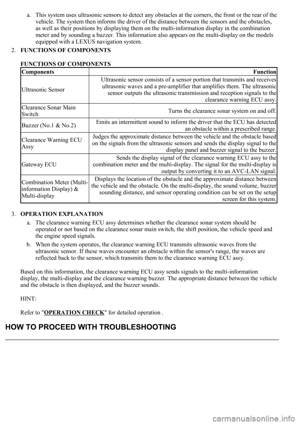
a. This system uses ultrasonic sensors to detect any obstacles at the corners, the front or the rear of the
vehicle. The system then informs the driver of the distance between the sensors and the obstacles,
as well as their positions by displaying them on the multi-information display in the combination
meter and by sounding a buzzer. This information also appears on the multi-display on the models
equipped with a LEXUS navigation system.
2.FUNCTIONS OF COMPONENTS
FUNCTIONS OF COMPONENTS
3.OPERATION EXPLANATION
a. The clearance warning ECU assy determines whether the clearance sonar system should be
operated or not based on the clearance sonar main switch, the shift position, the vehicle speed and
the engine speed signals.
b. When the system operates, the clearance warning ECU transmits ultrasonic waves from the
ultrasonic sensor. If these waves encounter an obstacle within the sensor's range, the waves are
reflected back to the sensor, which transmits them to the clearance warning ECU assy.
Based on this information, the clearance warning ECU assy sends signals to the multi-information
display, the multi-display and the clearance warning buzzer. The appropriate distance between the vehicle
and the obstacle is then displayed, and the buzzer sounds.
HINT:
Refer to "OPERATION CHECK
" for detailed operation .
ComponentsFunction
Ultrasonic Sensor
Ultrasonic sensor consists of a sensor portion that transmits and receives
ultrasonic waves and a pre-amplifier that amplifies them. The ultrasonic
sensor outputs the ultrasonic transmission and reception signals to the
clearance warning ECU assy.
Clearance Sonar Main
SwitchTurns the clearance sonar system on and off.
Buzzer (No.1 & No.2)Emits an intermittent sound to inform the driver that the ECU has detected
an obstacle within a prescribed range.
Clearance Warning ECU
AssyJudges the approximate distance between the vehicle and the obstacle based
on the signals from the ultrasonic sensors and sends the display signal to the
display panel and buzzer signal to the buzzer.
Gateway ECU
Sends the display signal of the clearance warning ECU assy to the
combination meter and the multi-display. The signal for the multi-display is
output by converting it to an AVC-LAN signal.
Combination Meter (Multi-
information Display) &
Multi-displayDisplays the location of the obstacle and the approximate distance between
the vehicle and the obstacle. On the multi-display, the sound volume, buzzer
sounding distance, and sensor operating condition can be set on the setup
screen for this system.
Page 1817 of 4500
Courtesy of TOYOTA MOTOR SALES, U.S.A., INC.
NG: REPAIR OR REPLACE HARNESS OR CONNECTOR
OK: REPLACE AIRBAG SENSOR ASSY CENTER (SEE HOW TO PROCEED WITH
TROUBLESHOOTING )
WIRING DIAGRAM
Fig. 70: Passenger'S Seat Belt Warning Lamp Wiring Diagram
Courtesy of TOYOTA MOTOR SALES, U.S.A., INC.
INSPECTION PROCEDURE
HINT:
Displa
y except for the seat belt warning indicator are shown in the navigation system (see HOW TO
Page 1818 of 4500

PROCEED WITH TROUBLESHOOTING) and A/C system (see HOW TO PROCEED WITH
TROUBLESHOOTING ).
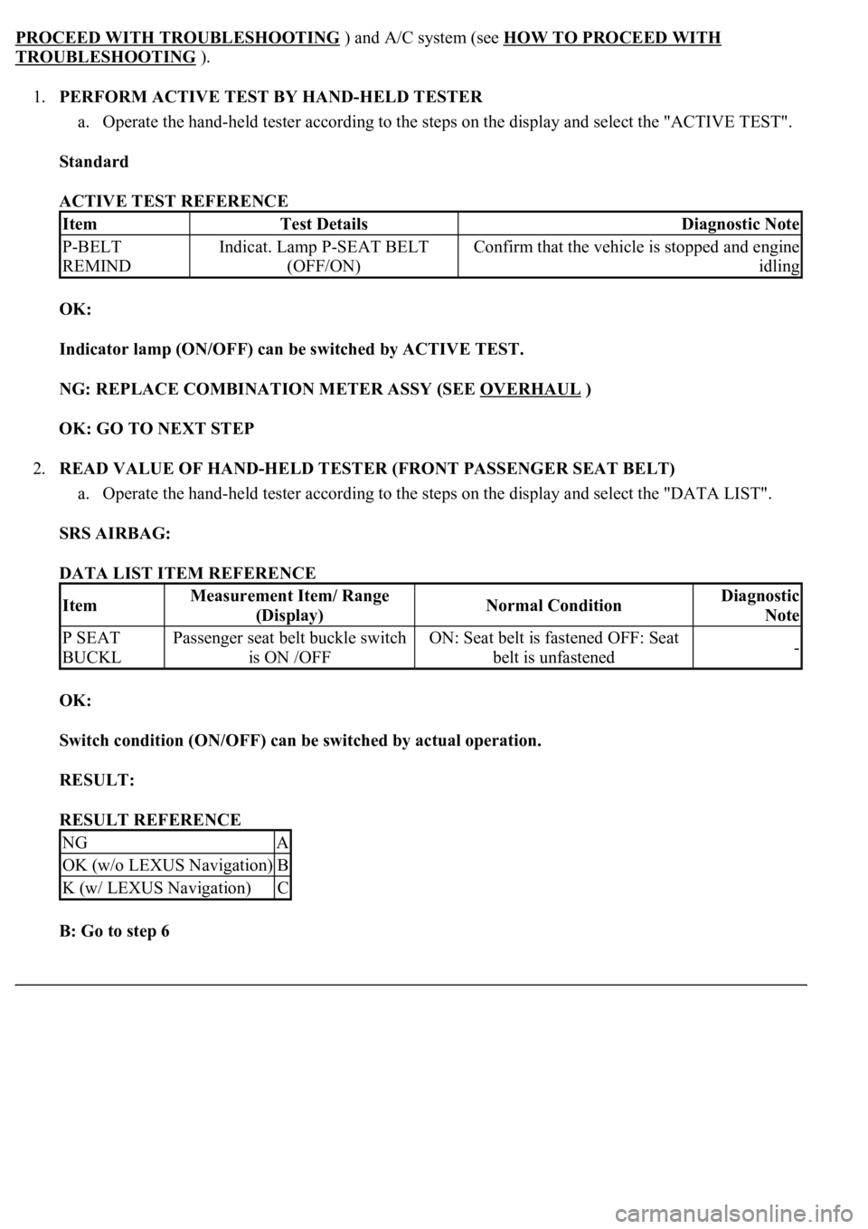
1.PERFORM ACTIVE TEST BY HAND-HELD TESTER
a. Operate the hand-held tester according to the steps on the display and select the "ACTIVE TEST".
Standard
ACTIVE TEST REFERENCE
OK:
Indicator lamp (ON/OFF) can be switched by ACTIVE TEST.
NG: REPLACE COMBINATION METER ASSY (SEE OVERHAUL
)
OK: GO TO NEXT STEP
2.READ VALUE OF HAND-HELD TESTER (FRONT PASSENGER SEAT BELT)
a. Operate the hand-held tester according to the steps on the display and select the "DATA LIST".
SRS AIRBAG:
DATA LIST ITEM REFERENCE
OK:
Switch condition (ON/OFF) can be switched by actual operation.
RESULT:
RESULT REFERENCE
B: Go to step 6
ItemTest DetailsDiagnostic Note
P-BELT
REMINDIndicat. Lamp P-SEAT BELT
(OFF/ON)Confirm that the vehicle is stopped and engine
idling
ItemMeasurement Item/ Range
(Display)Normal ConditionDiagnostic
Note
P SEAT
BUCKLPassenger seat belt buckle switch
is ON /OFFON: Seat belt is fastened OFF: Seat
belt is unfastened-
NGA
OK (w/o LEXUS Navigation)B
K (w/ LEXUS Navigation)C
Page 1991 of 4500
Fig. 2: Defogger System Diagram
Courtesy of TOYOTA MOTOR SALES, U.S.A., INC.
Communication Table
COMMUNICATION TABLE
1.GENERAL
The rear window defogger system's thin heater wires are attached to the inside of the rear window and
defog the window surface quickly. The indicator lamp illuminates while the system is operating. The
system automatically turns off after approximately 15 minutes.
2.FUNCTION OF MAIN COMPONENT
SenderReceiverSignalLine
Multi-display(1)A/C control assemblyRear defogger switch
signalBEAN
Center cluster integration
panel
(2)
A/C control assemblyRear defogger switch
signalBEAN/AVC-LAN
(1)w/ LEXUS navigation system
(2)w/o LEXUS navigation system
Page 1998 of 4500
c. Perform the ACTIVE TEST by following the directions on the tester screen.
A/C control assy:
A/C CONTROL ASSY - REFERENCE TABLE
CIRCUIT DESCRIPTION
When the defogger switch is turned on, a rear defogger activation request signal is input to the A/C control (A/C
ECU) from the multi-display
1 or center cluster integration panel2 . Then, the A/C control assembly outputs this
signal to the defogger relay (Marking: DEFOG) and the rear window defogger system is activated.
HINT:
1. w/ LEXUS navigation system
2. w/o LEXUS navigation system
WIRING DIAGRAM
ItemTest DetailsDiagnostic Note
DEFOGGER RLY-ROperate rear window defogger OFF/ON-