Page 1211 of 4500
Fig. 15: Wiring Diagram For Identifying Can J/C Connectors ( (W/O Lexus Navigation
System))
Courtesy of TOYOTA MOTOR SALES, U.S.A., INC.
Page 1224 of 4500

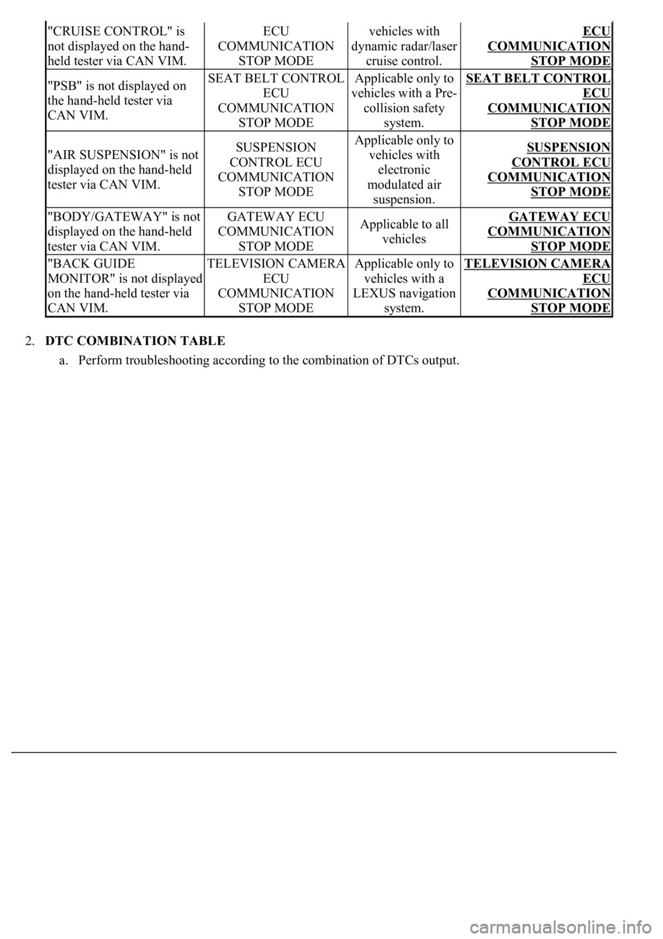
2.DTC COMBINATION TABLE
a. Perform troubleshooting according to the combination of DTCs output.
"CRUISE CONTROL" is
not displayed on the hand-
held tester via CAN VIM.ECU
COMMUNICATION
STOP MODEvehicles with
dynamic radar/laser
cruise control.ECU
COMMUNICATION
STOP MODE
"PSB" is not displayed on
the hand-held tester via
CAN VIM.SEAT BELT CONTROL
ECU
COMMUNICATION
STOP MODEApplicable only to
vehicles with a Pre-
collision safety
system.SEAT BELT CONTROL
ECU
COMMUNICATION
STOP MODE
"AIR SUSPENSION" is not
displayed on the hand-held
tester via CAN VIM.SUSPENSION
CONTROL ECU
COMMUNICATION
STOP MODEApplicable only to
vehicles with
electronic
modulated air
suspension.SUSPENSION
CONTROL ECU
COMMUNICATION
STOP MODE
"BODY/GATEWAY" is not
displayed on the hand-held
tester via CAN VIM.GATEWAY ECU
COMMUNICATION
STOP MODEApplicable to all
vehiclesGATEWAY ECU
COMMUNICATION
STOP MODE
"BACK GUIDE
MONITOR" is not displayed
on the hand-held tester via
CAN VIM.TELEVISION CAMERA
ECU
COMMUNICATION
STOP MODEApplicable only to
vehicles with a
LEXUS navigation
system.TELEVISION CAMERA
ECU
COMMUNICATION
STOP MODE
Page 1237 of 4500
Fig. 33: Identifying DLC3 Connector terminals
Courtesy of TOYOTA MOTOR SALES, U.S.A., INC.
a. Turn the ignition switch to the LOCK position.
b. Measure the resistance according to the value (s) in the table below.
Standard:
ECM CONNECTOR TERMINALS RESISTANCE
Tester connectionConditionSpecified valueResult
D1-6 (CANH) - D1-14
(CANL)Ignition Switch
OFF54 to 69 ohmsOK
D1-6 (CANH) - D1-14
(CANL)Ignition Switch
OFF69 ohms or more (w/o LEXUS Navigation
system)NG-A
D1-6 (CANH) - D1-14
(CANL)Ignition Switch
OFF69 ohms or more (w/ LEXUS Navigation
System)NG-B
D1-6 (CANH) - D1-14
(CANL)Ignition Switch
OFF54 ohms or less (w/o LEXUS Navigation
System)NG-C
Page 1238 of 4500
NG-A: CHECK CAN MAIN BUS LINE FOR DISCONNECTION (W/O LEXUS NAVIGATION
SYSTEM)
NG-B: CHECK CAN MAIN BUS LINE FOR DISCONNECTION (W/ LEXUS NAVIGATION
SYSTEM)
NG-C: CHECK CAN BUS LINES FOR SHORT CIRCUIT (W/O LEXUS NAVIGATION
SYSTEM)
NG-D: CHECK CAN BUS LINES FOR SHORT CIRCUIT (W/ LEXUS NAVIGATION SYSTEM)
OK: GO TO NEXT STEP
2.CHECK CAN BUS LINE FOR SHORT TO +B
Fig. 34: Identifying DLC3 Connector terminals
Courtesy of TOYOTA MOTOR SALES, U.S.A., INC.
D1-6 (CANH) - D1-14
(CANL)Ignition Switch
OFF54 ohms or less (w/ LEXUS Navigation
System)NG-D
Page 1239 of 4500
a. Measure the resistance according to the value (s) in the table below.
Standard:
ECM CONNECTOR TERMINALS RESISTANCE
HINT:
NG-A: w/o LEXUS Navigation System.
NG-B: w/ LEXUS Navigation System.
NG-A: CHECK CAN BUS LINE FOR SHORT TO +B (W/O LEXUS NAVIGATION SYSTEM)
NG-B: CHECK CAN BUS LINE FOR SHORT TO +B (W/ LEXUS NAVIGATION SYSTEM)
OK: GO TO NEXT STEP
3.CHECK CAN BUS LINE FOR SHORT TO GND
Tester ConnectionConditionSpecified value
D1-6 (CANH) - D1-16 (BAT)Ignition Switch OFF1 Mohms or more
D1-14 (CANL) - D1-16 (BAT)Ignition Switch OFF1 Mohms or more
Page 1240 of 4500
Fig. 35: Identifying DLC3 Connector terminals
Courtesy of TOYOTA MOTOR SALES, U.S.A., INC.
a. Measure the resistance according to the value (s) in the table below.
Standard:
ECM CONNECTOR TERMINALS RESISTANCE
HINT:
NG-A: w/o LEXUS Navigation System.
NG-B: w/ LEXUS Navigation System.
NG-A: CHECK CAN BUS LINE FOR SHORT TO GND (W/O LEXUS NAVIGATION SYSTEM)
Tester ConnectionConditionSpecified value
D1-4 (CG) - D1-6 (CANH)Ignition Switch OFF1 kohms or more
D1-4 (CG) - D1-14 (CANL)Ignition Switch OFF1 kohms or more
Page 1241 of 4500
NG-B: CHECK CAN BUS LINE FOR SHORT TO GND (W/ LEXUS NAVIGATION SYSTEM)
OK: HOW TO PROCEED WITH TROUBLESHOOTING
MODE DESCRIPTION
Fig. 36: Problem Symptom Diagnostic Chart
Courtesy of TOYOTA MOTOR SALES, U.S.A., INC.
WIRING DIAGRAM
Page 1277 of 4500
Fig. 73: Wiring Diagram - Can Main Bus Line For Disconnection (W/ LEXUS Navigation System)
Courtesy of TOYOTA MOTOR SALES, U.S.A., INC.
INSPECTION PROCEDURE
1.CHECK DLC3