Page 657 of 4500
Fig. 23: Removing Clips And Luggage Compartment Trim Cover Assy RH
Courtesy of TOYOTA MOTOR SALES, U.S.A., INC.
6.REMOVE NAVIGATION ECU W/BRACKET (W/ LEXUS NAVIGATION SYSTEM) (See
REPLACEMENT
)
7.REMOVE STEREO COMPONENT TUNER ASSY W/BRACKET (W/O LEXUS NAVIGATION
SYSTEM)
a. Disconnect the connector.
b. Remove the 2 nuts and stereo component tuner assy with bracket.
Page 658 of 4500
Fig. 24: Removing Nuts And Stereo Component Tuner Assy
Courtesy of TOYOTA MOTOR SALES, U.S.A., INC.
8.REMOVE STEREO COMPONENT TUNER ASSY W/BRACKET (W/ LEXUS NAVIGATION
SYSTEM)
a. Disconnect the connector.
b. Remove the nut and stereo component tuner assy with bracket.
Page 690 of 4500
Fig. 51: Removing Antenna Cord Sub-Assy
Courtesy of TOYOTA MOTOR SALES, U.S.A., INC.
REPLACEMENT
HINT:
See COMPONENTS .
See LOCATION .
Installation is in the reverse order of removal.
1.REMOVE INSTRUMENT PANEL SAFETY PAD SUB-ASSY (See step 19 on REPLACEMENT
)
2.REMOVE NAVIGATION ANTENNA ASSY
a. Remove the 2 screws and navigation antenna assy from the instrument panel safety pad.
Page 691 of 4500
Fig. 52: Removing Navigation Antenna Assy Screws
Courtesy of TOYOTA MOTOR SALES, U.S.A., INC.
REPLACEMENT
HINT:
See COMPONENTS .
Installation is in the reverse order of removal.
1.REMOVE INSTRUMENT PANEL FINISH PANEL LOWER CENTER (See step 26 on
REPLACEMENT
)
2.REMOVE CONSOLE PANEL SUB-ASSY UPPER (See step 38 on REPLACEMENT
)
3.REMOVE CIGARETTE LIGHTER ASSY
a. Rotate the socket cap counterclockwise to remove it.
b. Remove the cigarette lighter assy from the cigar-lighter hole bezel.
Page 705 of 4500

By converting the digital signals to analog, it can play music and other things. In general, CD
players can play 4.7-inch (12 cm) or 3.2-inch (8 cm) disc.
HINT:
Do not disassemble any part of the CD player.
Do not apply oil to the CD player.
Do not insert anything but a CD into the CD player.
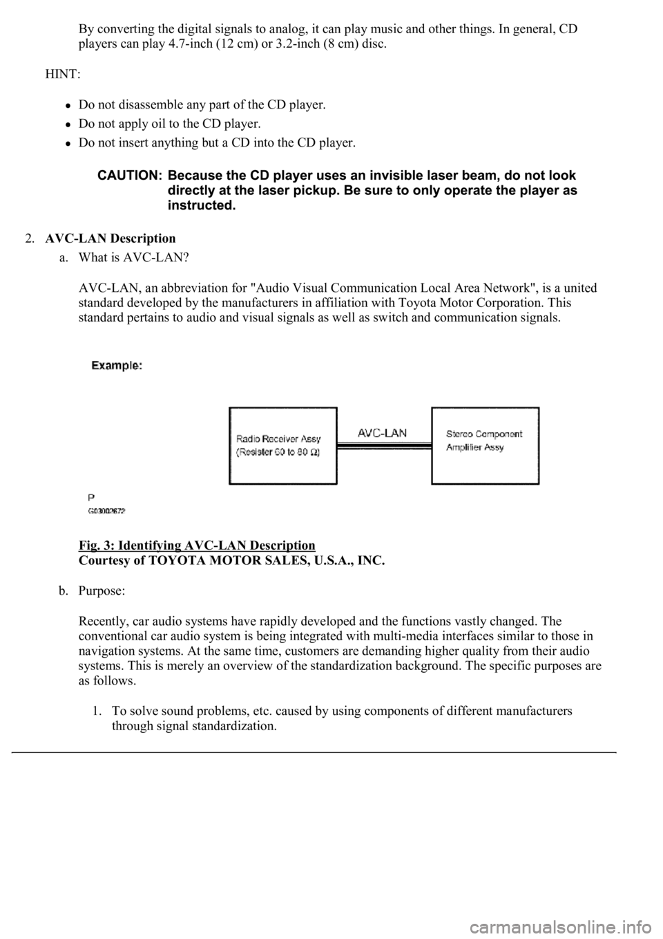
2.AVC-LAN Description
a. What is AVC-LAN?
AVC-LAN, an abbreviation for "Audio Visual Communication Local Area Network", is a united
standard developed by the manufacturers in affiliation with Toyota Motor Corporation. This
standard pertains to audio and visual signals as well as switch and communication signals.
Fig. 3: Identifying AVC
-LAN Description
Courtesy of TOYOTA MOTOR SALES, U.S.A., INC.
b. Purpose:
Recently, car audio systems have rapidly developed and the functions vastly changed. The
conventional car audio system is being integrated with multi-media interfaces similar to those in
navigation systems. At the same time, customers are demanding higher quality from their audio
systems. This is merely an overview of the standardization background. The specific purposes are
as follows.
1. To solve sound problems, etc. caused by using components of different manufacturers
through signal standardization.
Page 706 of 4500

2. To allow each manufacturer to concentrate on developing products they do best. From this,
reasonably priced products can be produced.
HINT:
If a +B or GND short is detected in the AVC-LAN circuit, communication is interrupted and the
audio system will stop functioning.
If an audio system is equipped with a navigation system, the multi-display unit acts as the master
unit. If the navigation system is not equipped, the audio head unit acts as the master unit instead. If
the radio and navigation assy is equipped, it is the master unit.
The radio and navigation assy provides resistance to make communication possible.
The car audio system with an AVC-LAN circuit has a diagnostic function.
Each component has a specified number (3-digit) called a physical address. Each function has a
number (2-digit) called a logical address.
3.Communication system outline
a. Components of the audio system communicate with each other via the AVC-LAN.
b. The master component of the AVC-LAN is a radio receiver assy with a 60 to 80 ohms resistor. This
is essential for communication.
c. If a short circuit or open circuit occurs in the AVC-LAN circuit, communication is interrupted and
the audio system will stop functioning.
4.Diagnostic function outline
a. The audio system has a diagnostic function (the result is indicated on the master unit).
b. A 3-digit hexadecimal component code (physical address) is allocated to each component on the
AVC-LAN. Using this code, the component in the diagnostic function can be displayed.
1.Vehicle brought into a workshop
2.Diagnostic questioning and symptom confirmation (SEE CUSTOMER PROBLEM ANALYSIS
CHECK )
Ask the customer about symptoms and confirm malfunctions. Fill out the Customer Problem Analysis
check sheet.
Pressing PWR switch does not turn on system (SEE PROBLEM SYMPTOMS TABLE
)
Other symptoms (go to step 3)
3.Check the diagnostic trouble codes (SEE SYSTEM CHECK MODE (DTC CHECK)
)
HINT:
If the audio system is equipped with a multi-display, check DTCs in the LEXUS NAVIGATION
SYSTEM section (SEE PRECAUTION
).
Page 719 of 4500

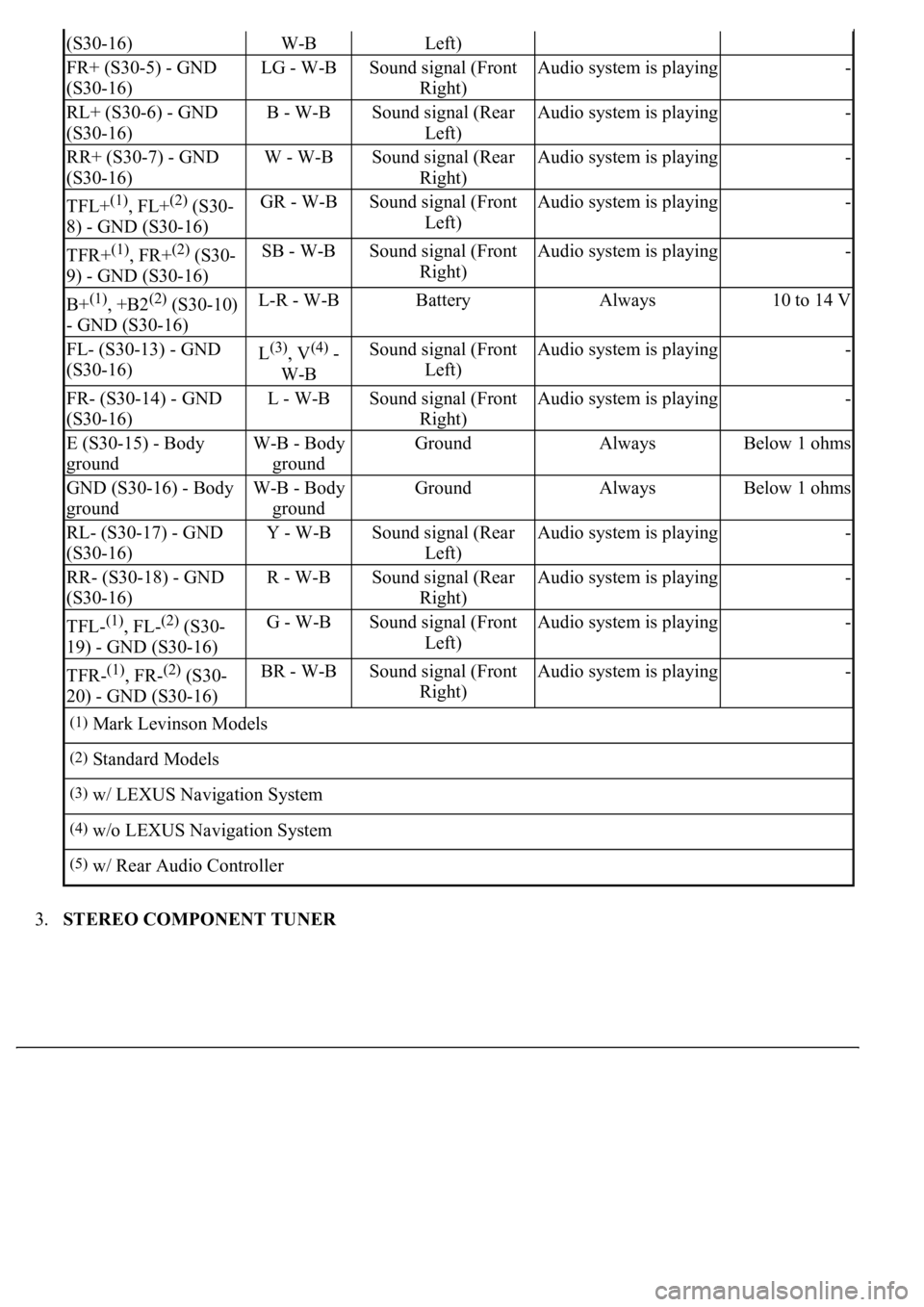
3.STEREO COMPONENT TUNER
(S30-16)W-BLeft)
FR+ (S30-5) - GND
(S30-16)LG - W-BSound signal (Front
Right)Audio system is playing-
RL+ (S30-6) - GND
(S30-16)B - W-BSound signal (Rear
Left)Audio system is playing-
RR+ (S30-7) - GND
(S30-16)W - W-BSound signal (Rear
Right)Audio system is playing-
TFL+(1), FL+(2) (S30-
8) - GND (S30-16)GR - W-BSound signal (Front
Left)Audio system is playing-
TFR+(1), FR+(2) (S30-
9) - GND (S30-16)SB - W-BSound signal (Front
Right)Audio system is playing-
B+(1), +B2(2) (S30-10)
- GND (S30-16)L-R - W-BBatteryAlways10 to 14 V
FL- (S30-13) - GND
(S30-16)L(3), V(4) -
W-BSound signal (Front
Left)Audio system is playing-
FR- (S30-14) - GND
(S30-16)L - W-BSound signal (Front
Right)Audio system is playing-
E (S30-15) - Body
groundW-B - Body
groundGroundAlwaysBelow 1 ohms
GND (S30-16) - Body
groundW-B - Body
groundGroundAlwaysBelow 1 ohms
RL- (S30-17) - GND
(S30-16)Y - W-BSound signal (Rear
Left)Audio system is playing-
RR- (S30-18) - GND
(S30-16)R - W-BSound signal (Rear
Right)Audio system is playing-
TFL-(1), FL-(2) (S30-
19) - GND (S30-16)G - W-BSound signal (Front
Left)Audio system is playing-
TFR-(1), FR-(2) (S30-
20) - GND (S30-16)BR - W-BSound signal (Front
Right)Audio system is playing-
(1)Mark Levinson Models
(2)Standard Models
(3)w/ LEXUS Navigation System
(4)w/o LEXUS Navigation System
(5)w/ Rear Audio Controller
Page 721 of 4500
4.AUDIO AND REAR A/C CONTROL SW
Fig. 17: Audio And Rear A/C Control SW ECU Terminal Connector
Courtesy of TOYOTA MOTOR SALES, U.S.A., INC.
TERMINAL DESCRIPTION CHART
ATX- (S31-20) -
GND (S31-25)R - W-BAVC-LAN
communication signalTurn ignition switch to
ACC2 to 3 V
MTX- (S31-21) -
GND (S31-25)B - W-BAVC-LAN
communication signalTurn ignition switch to
ACC2 to 3 V
GND (S31-25) -
Body groundW-B - Body
groundGroundAlwaysBelow 1 ohms
(1)w/ LEXUS Navigation System
Symbols (Terminal
No.)Wiring
ColorTerminal DescriptionConditionSpecification