Page 4450 of 4500
Fig. 10: Identifying Bluetooth Capable Cellular
Courtesy of TOYOTA MOTOR SALES, U.S.A., INC.
1.Vehicle brought into a workshop
2.Diagnostic questioning and symptom confirmation (see CUSTOMER PROBLEM ANALYSIS
CHECK )
Ask the customer about symptoms and confirm malfunctions. Fill out the Customer Problem Analysis
check sheet.
The screen displays nothing (go to step 6, proceed to "BLACK SCREEN (NO IMAGE APPEARS
ON NAVIGATION/AUDIO SCREEN)")
Other symptoms (go to step 3)
3.Confirm the system normal condition (see SYSTEM NORMAL CONDITION CHECK
)
Applicable (This is not a malfunction.)
Not applicable (go to step 4)
4.Check the diagnostic trouble codes (see DIAGNOSTIC TROUBLE CODE CHART
)
HINT:
If the system cannot enter the diagnosis mode, inspect each AVC-LAN communication signal and
Page 4451 of 4500

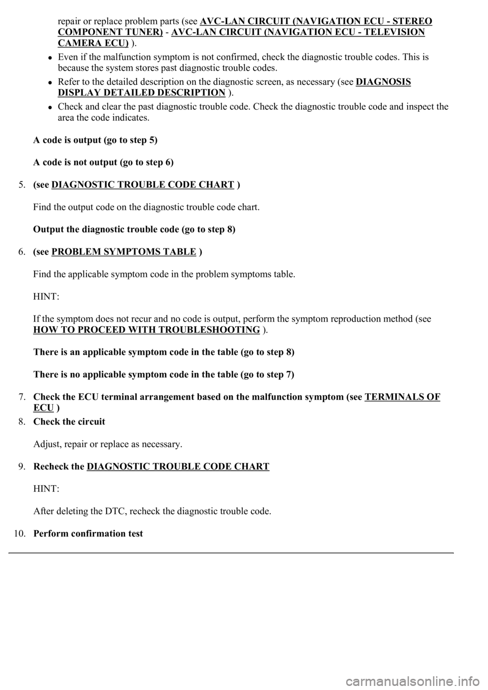
repair or replace problem parts (see AVC-LAN CIRCUIT (NAVIGATION ECU -STEREO
COMPONENT TUNER) - AVC-LAN CIRCUIT (NAVIGATION ECU - TELEVISION
CAMERA ECU) ).
Even if the malfunction symptom is not confirmed, check the diagnostic trouble codes. This is
because the system stores past diagnostic trouble codes.
Refer to the detailed description on the diagnostic screen, as necessary (see DIAGNOSIS
DISPLAY DETAILED DESCRIPTION ).
Check and clear the past diagnostic trouble code. Check the diagnostic trouble code and inspect the
area the code indicates.
A code is output (go to step 5)
A code is not output (go to step 6)
5.(see DIAGNOSTIC TROUBLE CODE CHART
)
Find the output code on the diagnostic trouble code chart.
Output the diagnostic trouble code (go to step 8)
6.(see PROBLEM SYMPTOMS TABLE
)
Find the applicable symptom code in the problem symptoms table.
HINT:
If the symptom does not recur and no code is output, perform the symptom reproduction method (see
HOW TO PROCEED WITH TROUBLESHOOTING
).
There is an applicable symptom code in the table (go to step 8)
There is no applicable symptom code in the table (go to step 7)
7.Check the ECU terminal arrangement based on the malfunction symptom (see TERMINALS OF
ECU )
8.Check the circuit
Adjust, repair or replace as necessary.
9.Recheck the DIAGNOSTIC TROUBLE CODE CHART
HINT:
After deleting the DTC, recheck the diagnostic trouble code.
10.Perform confirmation test
Page 4465 of 4500
Fig. 25: Displaying Diagnostic Menu
Courtesy of TOYOTA MOTOR SALES, U.S.A., INC.
2.Select "Navigation Check" from the "Diagnosis MENU" screen.
Page 4466 of 4500
Fig. 26: Displaying Navigation
Courtesy of TOYOTA MOTOR SALES, U.S.A., INC.
3.Select "GPS Information" from the "Navigation Check" screen.
Page 4467 of 4500
Fig. 27: Identifying GPS Information Chart
Courtesy of TOYOTA MOTOR SALES, U.S.A., INC.
4.When GPS information is displayed, check the GPS conditions.
HINT:
This screen is updated once per second when input signals to the vehicle are changed.
HINT:
This mode checks the vehicle signal status to the navigation ECU.
Illustrations may differ from the actual vehicle depending on the device settings and options. Therefore,
some detailed areas may not be shown exactly the same as on the actual vehicle.
1.Enter diagnostic mode (see DIAGNOSTIC START
-UP/FINISH ).
Page 4468 of 4500
Fig. 28: Displaying Diagnostic Chart
Courtesy of TOYOTA MOTOR SALES, U.S.A., INC.
2.Select "Navigation Check" from the "Diagnosis MENU" screen.
Page 4469 of 4500
Fig. 29: Displaying Navigation
Courtesy of TOYOTA MOTOR SALES, U.S.A., INC.
3.Select "Vehicle Sensors" from the "Navigation Check" screen.
Page 4471 of 4500
Fig. 31: Displaying Navigation Check Mode
Courtesy of TOYOTA MOTOR SALES, U.S.A., INC.
2.Select "Navigation Check" from the "Diagnosis MENU" screen.