Page 1497 of 4500
32.CONNECT CONNECTOR
a. Reconnect the yaw rate sensor sub bus line connector (J44) to the P-CAN J/C A side (w/earth
terminal).
33.CHECK CAN BUS LINE FOR SHORT TO GND (YAW RATE SENSOR SUB BUS LINE)
Fig. 282: Identifying DLC3 Connector terminals
Courtesy of TOYOTA MOTOR SALES, U.S.A., INC.
a. Disconnect the yaw rate sensor connector (Y1).
b. Measure the resistance according to the value (s) in the table below.
Standard:
DLC3 CONNECTOR TERMINALS RESISTANCE
OK: REPLACE YAW RATE SENSOR (SEE REPLACEMENT
)
Tester connectionConditionSpecified value
D1-6 (CANH) - D1-4 (CG)Ignition Switch OFF1 kohms or more
D1-14 (CANL) - D1-4 (CG)Ignition Switch OFF1 kohms or more
Page 1507 of 4500
a. Turn the ignition switch to the ON position.
b. Move the shift lever to the D position (when the front sonar and the front clearance sonar are
checked).
c. Move the shift lever to the R position (when the back sonar and the rear clearance sonar are
checked).
d. Turn the clearance sonar main switch on.
e. Move a diameter 60 mm (2.36 in.) pole around the sensor to measure the detection range of the
sensor.
Page 1509 of 4500
Front sonar:
CLEARANCE SONAR MAIN SWITCH
HINT:
Because sound waves are used for detection range measurement, the detection range may change
sli
ghtly due to the peripheral temperature.
Ignition
switchClearance sonar
main switchShift positionVehicle speedEngine speed
ONONIn any position
except P and R10 km/h (6
mph) or lessN position: 1,500 RPM or less
Except N position: 2,500 RPM or
less
Page 1511 of 4500
HINT:
Clearance sonar display does not appear on the multi-display if the shift lever is moved to the
R position.
Because sound waves are used for detection range measurement, the detection range may
chan
ge slightly due to the peripheral temperature.
Ignition
switchClearance sonar main
switchShift
positionVehicle speedEngine speed
ONONR position10 km/h (6 mph) or
less2,500 RPM or
less
Page 1513 of 4500
Rear clearance sonar:
CLEARANCE SONAR MAIN SWITCH
HINT:
Clearance sonar display does not appear on the multi-display if the shift lever is moved to the
R position.
Because sound waves are used for detection range measurement, the detection range may
chan
ge slightly due to the peripheral temperature.
Ignition
switchClearance sonar
main switchShift positionVehicle speedEngine speed
ONONIn any position
except P and R10 km/h (6
mph) or lessN position 1,500 RPM or less
Except N position 2,500 RPM or
less
Ignition
switchClearance sonar main
switchShift
positionVehicle speedEngine speed
ONONR position10 km/h (6 mph) or
less2,500 RPM or
less
Page 1514 of 4500
Fig. 8: Identifying Clearance Sonar Display
Courtesy of TOYOTA MOTOR SALES, U.S.A., INC.
2.INITIAL CHECK FUNCTION CHECK
a. Turn the ignition switch to the ON position.
b. Drive the engine at 2,500 RPM or less with the shift lever in any position except N, or at 1,500
RPM or less with the shift lever in the N position.
Page 1515 of 4500
c. After turning the ignition switch to the ON position, wait for 2 seconds or more, then turn the
clearance sonar main switch on. Check the multi-information display and the buzzer sounding
condition.
Standard:
After the main switch is turned on, the multi-information display shows the Fig. 9
below
for approximatel
y 2 seconds and the buzzer sounds for approximately 1 second then the
detection mode begins.
Fig. 9: Identifying Multi
-Information Display
Courtesy of TOYOTA MOTOR SALES, U.S.A., INC.
HINT:
Multi-information display:
The malfunctioning sensor blinks on the display when the wire harness or the connector is
faulty and requires repair or replacement, or when trouble is detected in the ultrasonic sensor
circuits. After the sensor operation returns to normal, the detection mode will finish
normall
y.
Page 1523 of 4500

HINT:
If the display shows "UNABLE TO CONNECT TO VEHICLE" after connecting the hand-held tester cable to
the DLC3 and turning the ignition switch to the ON position, there is either a problem with the vehicle or tester.
If communication is normal when connecting the tester to another vehicle, inspect the DLC3 on the
original vehicle.
If communication is still not possible when connecting the tester to another vehicle, the problem is
probably in the tester itself, so consult the Service Department listed in the tester's operator's manual.
1.CHECK DTCs
a. Prepare the hand-held tester.
b. Connect the hand-held tester to the DLC3 at the lower part of the instrument panel.
c. Turn the ignition switch to the ON position and turn the hand-held tester on.
d. Use the hand-held tester to check the DTCs and the freeze frame data, and note or print the results.
(Refer to the operator's manual for operating instructions.)
e. SEE DIAGNOSTIC TROUBLE CODE CHART
to confirm the details of the DTCs.
2.CLEAR DTCs
a. The following procedures clear the DTCs and freeze frame data.
1. When using the hand-held tester:
Operate the hand-held tester. (Refer to the operator's manual for operating
instructions.)
2. When not using the hand-held tester:
Disconnect the battery terminals.
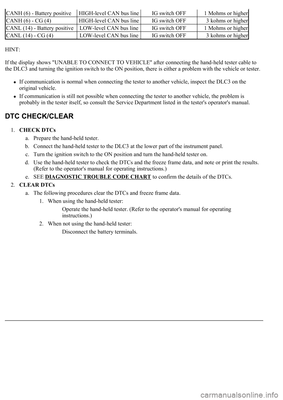
CANH (6) - Battery positiveHIGH-level CAN bus lineIG switch OFF1 Mohms or higher
CANH (6) - CG (4)HIGH-level CAN bus lineIG switch OFF3 kohms or higher
CANL (14) - Battery positiveLOW-level CAN bus lineIG switch OFF1 Mohms or higher
CANL (14) - CG (4)LOW-level CAN bus lineIG switch OFF3 kohms or higher