Page 1700 of 4500

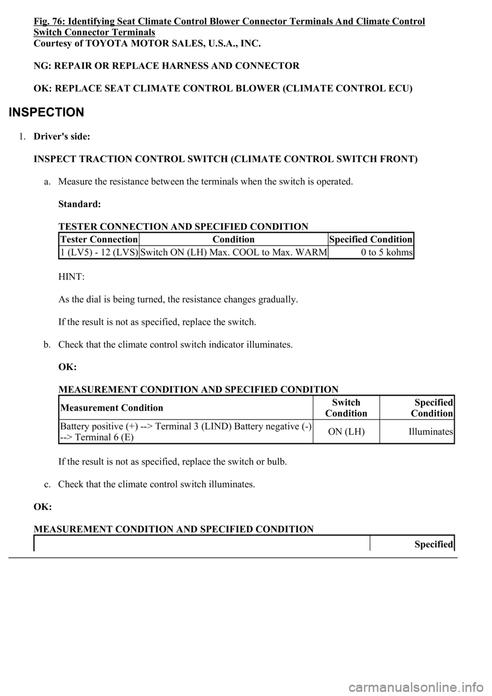
Fig. 76: Identifying Seat Climate Control Blower Connector Terminals And Climate Control
Switch Connector Terminals
Courtesy of TOYOTA MOTOR SALES, U.S.A., INC.
NG: REPAIR OR REPLACE HARNESS AND CONNECTOR
OK: REPLACE SEAT CLIMATE CONTROL BLOWER (CLIMATE CONTROL ECU)
1.Driver's side:
INSPECT TRACTION CONTROL SWITCH (CLIMATE CONTROL SWITCH FRONT)
a. Measure the resistance between the terminals when the switch is operated.
Standard:
TESTER CONNECTION AND SPECIFIED CONDITION
HINT:
As the dial is being turned, the resistance changes gradually.
If the result is not as specified, replace the switch.
b. Check that the climate control switch indicator illuminates.
OK:
MEASUREMENT CONDITION AND SPECIFIED CONDITION
If the result is not as specified, replace the switch or bulb.
c. Check that the climate control switch illuminates.
OK:
MEASUREMENT CONDITION AND SPECIFIED CONDITION
Tester ConnectionConditionSpecified Condition
1 (LV5) - 12 (LVS)Switch ON (LH) Max. COOL to Max. WARM0 to 5 kohms
Measurement ConditionSwitch
ConditionSpecified
Condition
Battery positive (+) --> Terminal 3 (LIND) Battery negative (-)
--> Terminal 6 (E)ON (LH)Illuminates
Specified
Page 1703 of 4500

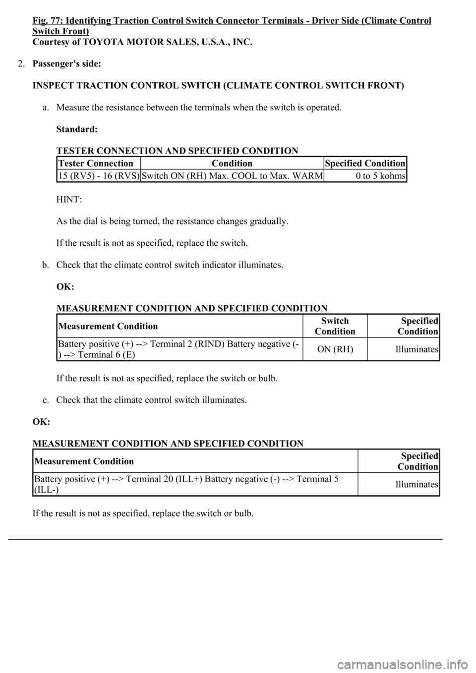
Fig. 77: Identifying Traction Control Switch Connector Terminals -Driver Side (Climate Control
Switch Front)
Courtesy of TOYOTA MOTOR SALES, U.S.A., INC.
2.Passenger's side:
INSPECT TRACTION CONTROL SWITCH (CLIMATE CONTROL SWITCH FRONT)
a. Measure the resistance between the terminals when the switch is operated.
Standard:
TESTER CONNECTION AND SPECIFIED CONDITION
HINT:
As the dial is being turned, the resistance changes gradually.
If the result is not as specified, replace the switch.
b. Check that the climate control switch indicator illuminates.
OK:
MEASUREMENT CONDITION AND SPECIFIED CONDITION
If the result is not as specified, replace the switch or bulb.
c. Check that the climate control switch illuminates.
OK:
MEASUREMENT CONDITION AND SPECIFIED CONDITION
If the result is not as specified, replace the switch or bulb.
Tester ConnectionConditionSpecified Condition
15 (RV5) - 16 (RVS)Switch ON (RH) Max. COOL to Max. WARM0 to 5 kohms
Measurement ConditionSwitch
ConditionSpecified
Condition
Battery positive (+) --> Terminal 2 (RIND) Battery negative (-
) --> Terminal 6 (E)ON (RH)Illuminates
Measurement ConditionSpecified
Condition
Battery positive (+) --> Terminal 20 (ILL+) Battery negative (-) --> Terminal 5
(ILL-)Illuminates
Page 1704 of 4500
Fig. 78: Identifying Traction Control Switch Connector Terminals - Passenger Side (Climate
Control Switch Front)
Page 1791 of 4500
Fig. 48: Identifying C12 And S42 Connectors
Courtesy of TOYOTA MOTOR SALES, U.S.A., INC.
NG: REPAIR OR REPLACE HARNESS AND CONNECTOR
OK: GO TO NEXT STEP
6.INSPECT ABS & TRACTION ACTUATOR ASSY (VSC)
a. Disconnect the S42 connector.
b. Measure the voltage according to the value (s) in the table below.
Standard
S42 connector VOLTAGE SPECIFICATIONS
NG: REPLACE COMBINATION METER ASSY (SEE OVERHAUL
)
Fig. 49: Identifying S42 Connector Terminals
Courtesy of TOYOTA MOTOR SALES, U.S.A., INC.
OK: GO TO BRAKE CONTROL SYSTEM (SEE HOW TO PROCEED WITH
TROUBLESHOOTING )
Tester ConnectionConditionSpecified Condition
S42-12 - Body groundIgnition switch ON10 to 14 V
Page 2486 of 4500

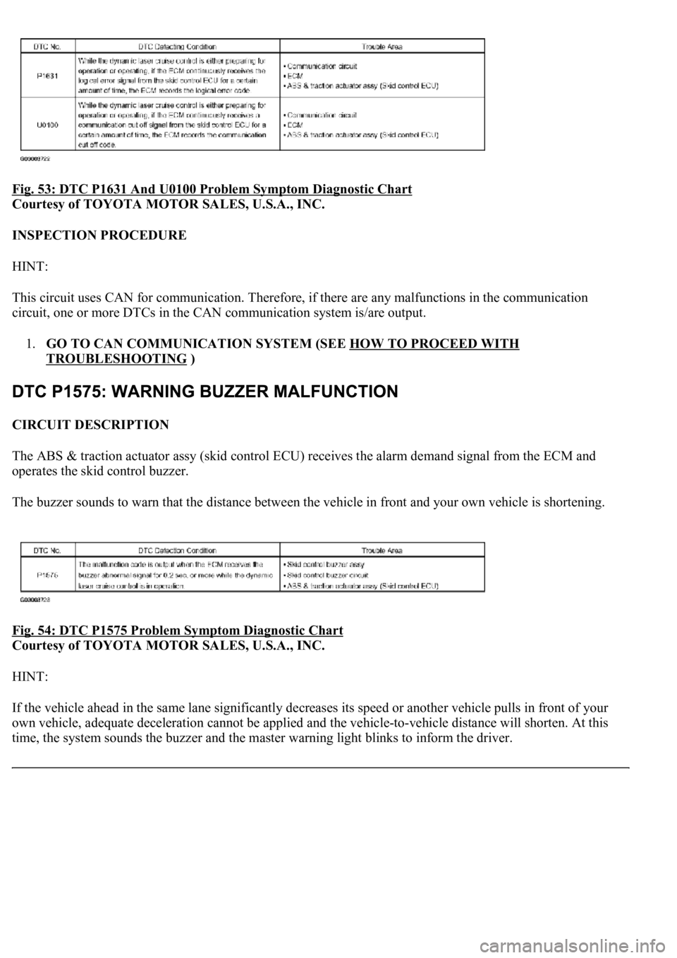
Fig. 53: DTC P1631 And U0100 Problem Symptom Diagnostic Chart
Courtesy of TOYOTA MOTOR SALES, U.S.A., INC.
INSPECTION PROCEDURE
HINT:
This circuit uses CAN for communication. Therefore, if there are any malfunctions in the communication
circuit, one or more DTCs in the CAN communication system is/are output.
1.GO TO CAN COMMUNICATION SYSTEM (SEE HOW TO PROCEED WITH
TROUBLESHOOTING )
CIRCUIT DESCRIPTION
The ABS & traction actuator assy (skid control ECU) receives the alarm demand signal from the ECM and
operates the skid control buzzer.
The buzzer sounds to warn that the distance between the vehicle in front and your own vehicle is shortening.
Fig. 54: DTC P1575 Problem Symptom Diagnostic
Chart
Courtesy of TOYOTA MOTOR SALES, U.S.A., INC.
HINT:
If the vehicle ahead in the same lane significantly decreases its speed or another vehicle pulls in front of your
own vehicle, adequate deceleration cannot be applied and the vehicle-to-vehicle distance will shorten. At this
time, the s
ystem sounds the buzzer and the master warning light blinks to inform the driver.
Page 2587 of 4500

CIRCUIT DESCRIPTION
The ECM sends signals such as A/T information signal, dynamic radar cruise control operation signal, brake
operation demand signal, buzzer operation demand signal and low speed mode signal, etc. to the skid control
ECU when the dynamic radar cruise control is in operation.
<0037004b004800030028002600300003004c005600030057004b0048000300520051004f005c000300460052005000530052005100480051005700030057004b004400570003004b0044005600030044000300490058005100460057004c00520051000300
57005200030055004800460052005500470003004400510047[ output the DTCs in the dynamic radar cruise
control system. Therefore if the skid control ECU detects a communication error from the ECM, it sends the
malfunction signal back to the ECM.
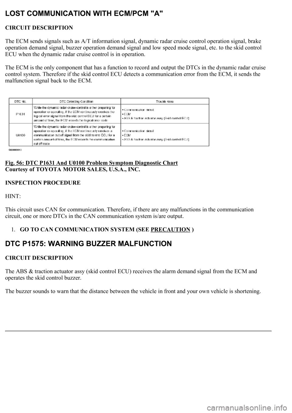
Fig. 56: DTC P1631 And U0100 Problem Symptom Diagnostic Chart
Courtesy of TOYOTA MOTOR SALES, U.S.A., INC.
INSPECTION PROCEDURE
HINT:
This circuit uses CAN for communication. Therefore, if there are any malfunctions in the communication
circuit, one or more DTCs in the CAN communication system is/are output.
1.GO TO CAN COMMUNICATION SYSTEM (SEE PRECAUTION
)
CIRCUIT DESCRIPTION
The ABS & traction actuator assy (skid control ECU) receives the alarm demand signal from the ECM and
operates the skid control buzzer.
The buzzer sounds to warn that the distance between the vehicle in front and
your own vehicle is shortening.
Page 3883 of 4500
Fig. 94: Inspecting RR S/SHADE Relay
Courtesy of TOYOTA MOTOR SALES, U.S.A., INC.
Standard:
RR S/SHADE RELAY - RESISTANCE TABLE
If the result is not as specified, replace the relay.
2.INSPECT TRACTION CONTROL SWITCH
(REAR SUNSHADE SWITCH FOR FRONT SIDE)
a. Measure the resistance of the switch.
Standard:
Tester ConnectionSpecified Condition
3 - 510 kohms or higher
3 - 5Below 1 ohms (when battery voltage is applied to
terminals 1 and 2)
Page 3884 of 4500
TRACTION CONTROL SWITCH - RESISTANCE TABLE
Fig. 95: Inspecting Traction Control Switch (Rear Sunshade Switch For Front Side)
Courtesy of TOYOTA MOTOR SALES, U.S.A., INC.
If the result is not as specified, replace the switch.
3.INSPECT REAR SUNSHADE SWITCH
(REAR SIDE)
a. Measure the resistance of the switch.
Standard:
REAR SUNSHADE SWITCH - RESISTANCE TABLE
Tester ConnectionSwitch ConditionSpecified Condition
6 - 7ONBelow 1 ohms
6 - 7OFF10 kohms or higher
Tester ConnectionSwitch ConditionSpecified Condition
1 - 2ONBelow 1 ohms
1 - 2OFF10 kohms or higher