Page 390 of 4500

a. Connect the hand-held tester to the DLC3.
b. Turn the ignition switch to the ON position and push the hand-held tester main switch on.
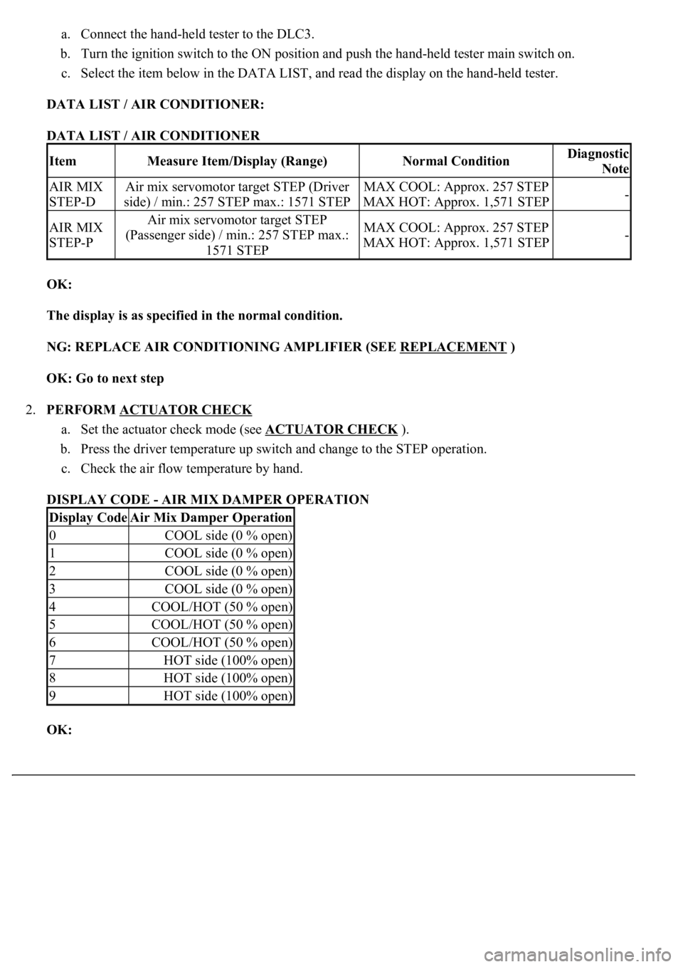
c. Select the item below in the DATA LIST, and read the display on the hand-held tester.
DATA LIST / AIR CONDITIONER:
DATA LIST / AIR CONDITIONER
OK:
The display is as specified in the normal condition.
NG: REPLACE AIR CONDITIONING AMPLIFIER (SEE REPLACEMENT
)
OK: Go to next step
2.PERFORM ACTUATOR CHECK
a. Set the actuator check mode (see ACTUATOR CHECK
).
b. Press the driver temperature up switch and change to the STEP operation.
c. Check the air flow temperature by hand.
DISPLAY CODE - AIR MIX DAMPER OPERATION
OK:
ItemMeasure Item/Display (Range)Normal ConditionDiagnostic
Note
AIR MIX
STEP-DAir mix servomotor target STEP (Driver
side) / min.: 257 STEP max.: 1571 STEPMAX COOL: Approx. 257 STEP
MAX HOT: Approx. 1,571 STEP-
AIR MIX
STEP-PAir mix servomotor target STEP
(Passenger side) / min.: 257 STEP max.:
1571 STEPMAX COOL: Approx. 257 STEP
MAX HOT: Approx. 1,571 STEP-
Display CodeAir Mix Damper Operation
0COOL side (0 % open)
1COOL side (0 % open)
2COOL side (0 % open)
3COOL side (0 % open)
4COOL/HOT (50 % open)
5COOL/HOT (50 % open)
6COOL/HOT (50 % open)
7HOT side (100% open)
8HOT side (100% open)
9HOT side (100% open)
Page 413 of 4500

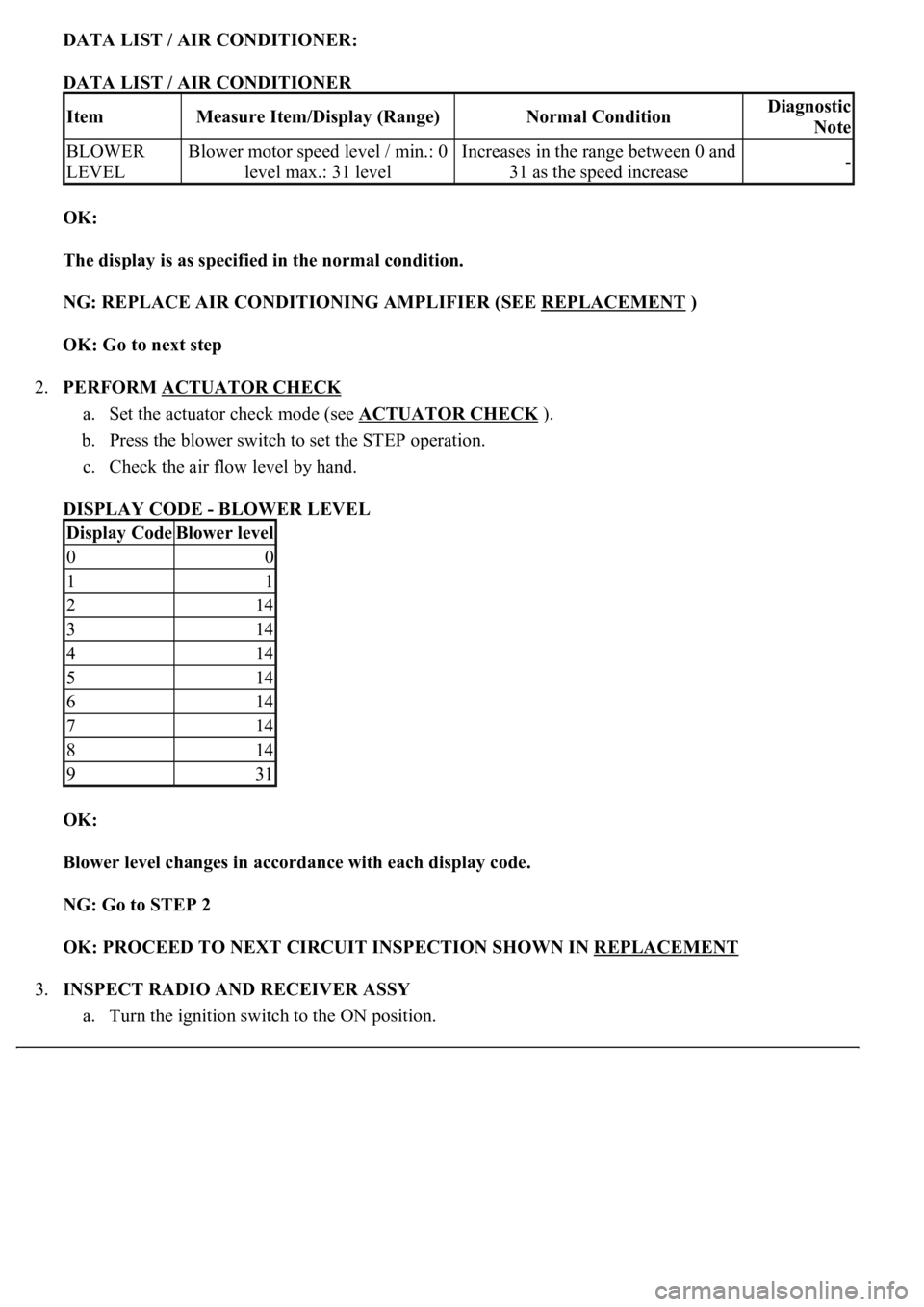
DATA LIST / AIR CONDITIONER:
DATA LIST / AIR CONDITIONER
OK:
The display is as specified in the normal condition.
NG: REPLACE AIR CONDITIONING AMPLIFIER (SEE REPLACEMENT
)
OK: Go to next step
2.PERFORM ACTUATOR CHECK
a. Set the actuator check mode (see ACTUATOR CHECK
).
b. Press the blower switch to set the STEP operation.
c. Check the air flow level by hand.
DISPLAY CODE - BLOWER LEVEL
OK:
<0025004f0052005a004800550003004f004800590048004f00030046004b00440051004a004800560003004c0051000300440046004600520055004700440051004600480003005a004c0057004b0003004800440046004b00030047004c00560053004f00
44005c000300460052004700480011[
NG: Go to STEP 2
OK: PROCEED TO NEXT CIRCUIT INSPECTION SHOWN IN REPLACEMENT
3.INSPECT RADIO AND RECEIVER ASSY
a. Turn the ignition switch to the ON position.
ItemMeasure Item/Display (Range)Normal ConditionDiagnostic
Note
BLOWER
LEVELBlower motor speed level / min.: 0
level max.: 31 levelIncreases in the range between 0 and
31 as the speed increase-
Display CodeBlower level
00
11
214
314
414
514
614
714
814
931
Page 2000 of 4500

that the A/C control is turned on and off.
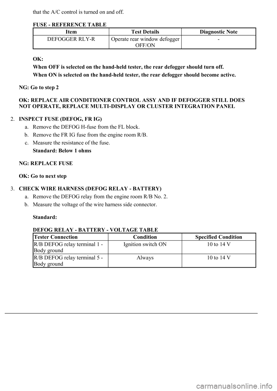
FUSE - REFERENCE TABLE
OK:
When OFF is selected on the hand-held tester, the rear defogger should turn off.
When ON is selected on the hand-held tester, the rear defogger should become active.
NG: Go to step 2
OK: REPLACE AIR CONDITIONER CONTROL ASSY AND IF DEFOGGER STILL DOES
NOT OPERATE, REPLACE MULTI-DISPLAY OR CLUSTER INTEGRATION PANEL
2.INSPECT FUSE (DEFOG, FR IG)
a. Remove the DEFOG H-fuse from the FL block.
b. Remove the FR IG fuse from the engine room R/B.
c. Measure the resistance of the fuse.
Standard: Below 1 ohms
NG: REPLACE FUSE
OK: Go to next step
3.CHECK WIRE HARNESS (DEFOG RELAY - BATTERY)
a. Remove the DEFOG relay from the engine room R/B No. 2.
b. Measure the voltage of the wire harness side connector.
Standard:
DEFOG RELAY - BATTERY - VOLTAGE TABLE
ItemTest DetailsDiagnostic Note
DEFOGGER RLY-ROperate rear window defogger
OFF/ON-
Tester ConnectionConditionSpecified Condition
R/B DEFOG relay terminal 1 -
Body groundIgnition switch ON10 to 14 V
R/B DEFOG relay terminal 5 -
Body groundAlways10 to 14 V
Page 2006 of 4500
Fig. 12: Checking Wire Harness (Defog Relay -A/C Control Assy)
Courtesy of TOYOTA MOTOR SALES, U.S.A., INC.
NG: REPAIR OR REPLACE HARNESS AND CONNECTOR
OK: Go to next step
7.INSPECT REAR WINDOW DEFOGGER (WIRE) (See step 3 in INSPECTION
)
NG: REPLACE REAR WINDOW DEFOGGER
OK: REPLACE AIR CONDITIONER CONTROL ASSY
Page 4220 of 4500
Fig. 35: Removing Heater Control Base Brackets No. 1
Courtesy of TOYOTA MOTOR SALES, U.S.A., INC.
9.REMOVE AIR CONDITIONER CONTROL ASSEMBLY
a. Disconnect the connector.
b. Remove the 4 screws, release the 4 claws and remove the air conditioner control assembly.
Page 4221 of 4500
Fig. 36: Removing Air Conditioner Control Assembly
Courtesy of TOYOTA MOTOR SALES, U.S.A., INC.
10.REMOVE HEATER CONTROL HOUSING
a. Remove the 2 screws, release the 4 claws and remove the heater control housin
g.
Page 4224 of 4500
Fig. 39: Removing Heater Control Base Sub-Assy
Courtesy of TOYOTA MOTOR SALES, U.S.A., INC.
13.REMOVE AIR CONDITIONER PANEL SUB-ASSY
COMPONENTS
Page 4303 of 4500
Fig. 113: Removing Rear Air Conditioning Unit Assy (W/Cooling Box Models)
Courtesy of TOYOTA MOTOR SALES, U.S.A., INC.
b. Disconnect the connector.
c. Remove the 2 nuts and 2 bolts.
d. Remove the rear air conditioner unit ass
y.