Page 1576 of 4500
Fig. 65: Identifying CLSW Terminals
Courtesy of TOYOTA MOTOR SALES, U.S.A., INC.
OK: REPLACE CLEARANCE WARNING ECU ASSY (SEE REPLACEMENT
)
NG: Go To Next Step.
3.CHECK HARNESS AND CONNECTOR (CLEARANCE WARNING ECU ASSY - BODY
GROUND)
a. Disconnect the C17 connector from the clearance warning ECU assy.
b. Measure the resistance according to the value (s) in the table below.
Standard:
TESTER CONNECTION SPECIFIED CONDITION
Tester connectionConditionSpecified condition
C17-7 (MGND) - Body groundAlwaysBelow 1 ohms
Page 1793 of 4500

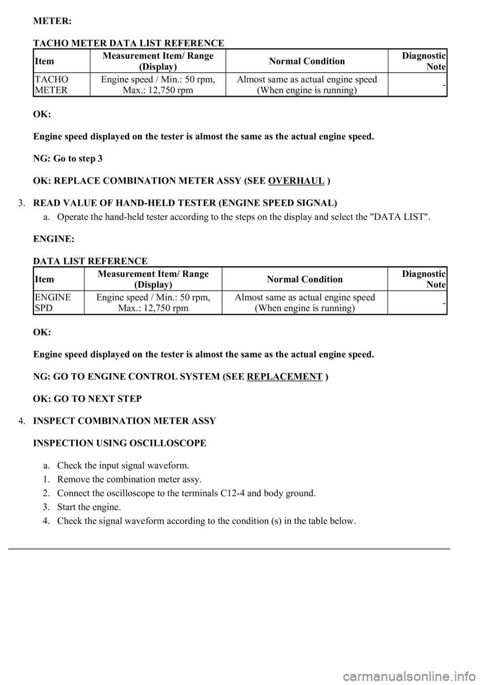
METER:
TACHO METER DATA LIST REFERENCE
OK:
Engine speed displayed on the tester is almost the same as the actual engine speed.
NG: Go to step 3
OK: REPLACE COMBINATION METER ASSY (SEE OVERHAUL
)
3.READ VALUE OF HAND-HELD TESTER (ENGINE SPEED SIGNAL)
a. Operate the hand-held tester according to the steps on the display and select the "DATA LIST".
ENGINE:
DATA LIST REFERENCE
OK:
Engine speed displayed on the tester is almost the same as the actual engine speed.
NG: GO TO ENGINE CONTROL SYSTEM (SEE REPLACEMENT
)
OK: GO TO NEXT STEP
4.INSPECT COMBINATION METER ASSY
INSPECTION USING OSCILLOSCOPE
a. Check the input signal waveform.
1. Remove the combination meter assy.
2. Connect the oscilloscope to the terminals C12-4 and body ground.
3. Start the engine.
4. Check the si
gnal waveform according to the condition (s) in the table below.
ItemMeasurement Item/ Range
(Display)Normal ConditionDiagnostic
Note
TACHO
METEREngine speed / Min.: 50 rpm,
Max.: 12,750 rpmAlmost same as actual engine speed
(When engine is running)-
ItemMeasurement Item/ Range
(Display)Normal ConditionDiagnostic
Note
ENGINE
SPDEngine speed / Min.: 50 rpm,
Max.: 12,750 rpmAlmost same as actual engine speed
(When engine is running)-
Page 1798 of 4500
Courtesy of TOYOTA MOTOR SALES, U.S.A., INC.
OK: GO TO ENGINE CONTROL SYSTEM (SEE REPLACEMENT
)
WIRING DIAGRAM
Fig. 55: Fuel Receiver Gauge Wiring Diagram
Courtesy of TOYOTA MOTOR SALES, U.S.A., INC.
INSPECTION PROCEDURE
1.PERFORM ACTIVE TEST BY HAND-HELD TESTER
a. Operate the hand-held tester according to the steps on the display and select the "ACTIVE TEST".
METER:
METER ACTIVE TEST REFERENCE
OK:
Needle indication is normal.
NG: REPLACE COMBINATION METER ASSY (SEE OVERHAUL
)
ItemTest DetailsDiagnostic Note
FUEL GAUGEOFF, EMPTY, 1/2, FULL-
Page 1811 of 4500
OK:
Needle indication is normal.
NG: REPLACE COMBINATION METER ASSY (SEE OVERHAUL
)
OK: GO TO NEXT STEP
2.READ VALUE OF HAND-HELD TESTER (ENGINE COOLANT)
a. Operate the hand-held tester according to the steps on the display and select the "DATA LIST".
ENGINE:
DATA LIST REFERENCE
OK:
Coolant temperature displayed on the tester is between 80°C (176°F) and 95°C (203°F) after
warning up.
NG: GO TO ENGINE CONTROL SYSTEM (SEE REPLACEMENT
)
OK: GO TO NEXT STEP
3.REPLACE COMBINATION METER ASSY
OK:
Normal operation
NG: GO TO ENGINE CONTROL SYSTEM (SEE REPLACEMENT
)
OK: END
WIRING DIAGRAM
ItemTest DetailsDiagnostic Note
COOLANT TEMPLOW /NORMAL /HI-
ItemMeasurement Item/ Range
(Display)Normal ConditionDiagnostic Note
COOLANT
TEMPCoolant Temperature / Min.: -
40°C (-40°F), Max.: 140°C
(284 °F)After warming up: 80
to 95°C (176 to 203°
F)If the value is "-40°C (-40°F)" or
"140°C (284°F)", sensor circuit is
open or shorted.
Page 1862 of 4500
Fig. 11: Measuring resistance of switch
Courtesy of TOYOTA MOTOR SALES, U.S.A., INC.
REPLACEMENT
1.REMOVE V-BANK COVER
2.REMOVE AIR CLEANER INLET NO.1 (See REPLACEMENT
)
3.DRAIN ENGINE COOLANT
a. Remove the 2 radiator caps from the radiator reservoir and radiator.
b. Loosen the radiator drain plug and 2 drain cock plugs, then drain the coolant.
Page 1865 of 4500
Fig. 14: Adding Coolant To Full Line For Radiator And Reservoir
Courtesy of TOYOTA MOTOR SALES, U.S.A., INC.
5.CHECK FOR ENGINE COOLANT LEAKS
6.INSTALL AIR CLEANER INLET NO.1 (See REPLACEMENT
)
7.INSTALL V-BANK COVER
COMPONENTS
Page 1868 of 4500
Fig. 17: Identifying Water Pump Component Assy (3 Of 2)
Courtesy of TOYOTA MOTOR SALES, U.S.A., INC.
REPLACEMENT
Page 1869 of 4500
1.DISCONNECT BATTERY NEGATIVE TERMINAL
2.DRAIN ENGINE COOLANT (See REPLACEMENT
)
3.REMOVE ENGINE UNDER COVER NO.1
4.REMOVE RADIATOR ASSY
5.REMOVE TIMING BELT (See REPLACEMENT
)
6.REMOVE WATER INLET HOUSING
a. Disconnect the water hose and remove the 2 bolts, inlet housing and O-ring.
Fig. 18: Disconnecting Water Hose
Courtesy of TOYOTA MOTOR SALES, U.S.A., INC.
7.REMOVE TIMING BELT IDLER SUB-ASSY NO.2 (See OVERHAUL
)
8.REMOVE WATER PUMP ASSY
a. Remove the 5 bolts, water pump and
gasket.