Page 1872 of 4500
Fig. 21: Installing Water Inlet Housing With Bolts
Courtesy of TOYOTA MOTOR SALES, U.S.A., INC.
11.INSTALL TIMING BELT IDLER SUB-ASSY NO.2 (See OVERHAUL
)
12.INSTALL TIMING BELT (See REPLACEMENT
)
13.INSTALL RADIATOR ASSY (See REPLACEMENT
)
14.REFILL ENGINE COOLANT (See REPLACEMENT
)
15.CONNECT BATTERY NEGATIVE TERMINAL
16.CHECK FOR ENGINE COOLANT LEAKS (See ON
-VEHICLE INSPECTION )
17.INSTALL ENGINE UNDER COVER NO.1
INSPECTION
1.INSPECT WATER PUMP ASSY
a. Visuall
y<00030046004b00480046004e00030057004b004800030044004c00550003004b0052004f004800030044005100470003005a00440057004800550003004b0052004f004800030049005200550003004600520052004f0044005100570003004f0048004400
4e0044[ge.
Page 1873 of 4500
If leakage is found, replace the water pump and timing belt.
b. Turn the pulley, and check that the water pump bearing moves smoothly and quietly.
If it moves roughly or noisily, replace the water pump.
Fig. 22: Inspecting Water Pump Assy
Courtesy of TOYOTA MOTOR SALES, U.S.A., INC.
REPLACEMENT
1.REMOVE AIR CLEANER INLET NO.1 (See REPLACEMENT
)
2.DRAIN ENGINE COOLANT (See REPLACEMENT
)
3.REMOVE THERMOSTAT
a. Remove the 3 nuts and disconnect the water inlet from the water inlet housing.
b. Remove the thermostat.
c. Remove the
gasket from the thermostat.
Page 1876 of 4500
Fig. 25: Installing Water Inlet With Nuts
Courtesy of TOYOTA MOTOR SALES, U.S.A., INC.
5.REFILL ENGINE COOLANT (See REPLACEMENT
)
6.CHECK FOR ENGINE COOLANT LEAKS (See ON
-VEHICLE INSPECTION )
7.INSTALL AIR CLEANER INLET NO.1 (See REPLACEMENT
)
ON-VEHICLE CLEANING
1.INSPECT FINS BLOCKAGE
a. Check that the radiator and condenser are not blocked with leaves, dirt, or insects. Clean the hose
connection.
If the fins are clo
gged, wash them with water or a steam cleaner and dry with compressed air.
Page 1879 of 4500
Fig. 28: Identifying Radiator Assy Component (2 Of 2)
Courtesy of TOYOTA MOTOR SALES, U.S.A., INC.
REPLACEMENT
1.DISCONNECT BATTERY NEGATIVE TERMINAL
2.REMOVE ENGINE UNDER COVER NO.1
Page 1880 of 4500
3.REMOVE AIR CLEANER INLET NO.1
4.DRAIN ENGINE COOLANT (See REPLACEMENT
)
5.REMOVE V-BANK COVER
6.REMOVE INTAKE AIR CONNECTOR PIPE
7.DISCONNECT RADIATOR HOSE NO.1
8.DISCONNECT RADIATOR HOSE NO.2
9.DISCONNECT OIL COOLER INLET TUBE NO.1
10.DISCONNECT OIL COOLER OUTLET TUBE NO.1
11.REMOVE AIR CLEANER ASSY
12.REMOVE RADIATOR AND FAN ASSEMBLY
a. Disconnect the cooling fan ECU connector.
b. Remove the 2 nuts and 2 radiator upper supports.
c. Remove the radiator and fan assembly.
d. Remove the 2 radiator lower supports.
Fig. 29: Removing Nuts And Radiator Upper Supports
Courtesy of TOYOTA MOTOR SALES, U.S.A., INC.
Page 1881 of 4500

13.REMOVE FAN ASSY
a. Disconnect the radiator reservoir hose from the radiator.
b. Remove the 6 bolts and fan.
14.INSTALL FAN ASSY
a. Install the fan with the 6 bolts.
Torque: 5.0 Nm (51 kgfcm, 44 in.lbf)
b. Connect the radiator reservoir hose to the radiator.
15.INSTALL RADIATOR AND FAN ASSEMBLY
a. Install the 2 radiator lower supports to the radiator.
b. Attach the 2 radiator lower supports on the radiator to the body bracket.
c. Install the radiator and fan assembly with the 2 radiator upper supports and 2 nuts.
Torque: 13.5 N m (138 kgf cm, 10 ft lbf)
d. Connect the cooling fan ECU connector.
16.INSTALL AIR CLEANER ASSY
17.INSTALL AIR CLEANER INLET NO.1
18.REFILL ENGINE COOLANT (See REPLACEMENT
)
19.CHECK FOR ENGINE COOLANT LEAKS
20.INSTALL ENGINE UNDER COVER NO.1
21.CONNECT BATTERY NEGATIVE TERMINAL
OVERHAUL
1.REMOVE PACKING
2.REMOVE RADIATOR CAP SUB-ASSY
3.REMOVE DRAIN PLUG
a. Remove the drain plug.
b. Remove the O-ring.
4.ASSEMBLE SST
SST 09230-01010
a. Install the claw to the overhaul handle, inserting it in the hole in part A as shown in the illustration
b. While gripping the handle, adjust the stopper bolt so that dimension B is as shown in the
illustration.
Page 1898 of 4500
HINT:
The installation procedures are the removal procedures in reverse order. However, only installation procedures
requiring additional information are included.
1.DRAIN ENGINE COOLANT FROM RADIATOR (See REPLACEMENT
)
2.REMOVE AIR CLEANER INLET NO.1
3.REMOVE AIR CLEANER ASSY (See REPLACEMENT
)
4.DISCONNECT RADIATOR HOSE NO.1
5.REMOVE FAN ASSY
a. Disconnect the connector.
b. Remove the 6 bolts and fan.
6.REMOVE COOLING FAN ECU
a. Disconnect the 2 connectors.
b. Remove the 2 screws and ECU.
7.REMOVE FAN
a. Remove the 2 nuts and 2 fans.
8.REMOVE COOLING FAN MOTOR
a. Disconnect the 2 wires from the fan shroud.
b. Remove the 6 screws and 2 cooling fan motors.
Page 1925 of 4500

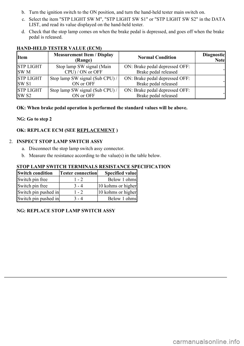
b. Turn the ignition switch to the ON position, and turn the hand-held tester main switch on.
c. Select the item "STP LIGHT SW M", "STP LIGHT SW S1" or "STP LIGHT SW S2" in the DATA
LIST, and read its value displayed on the hand-held tester.
d. Check that the stop lamp comes on when the brake pedal is depressed, and goes off when the brake
pedal is released.
HAND-HELD TESTER VALUE (ECM)
OK: When brake pedal operation is performed the standard values will be above.
NG: Go to step 2
OK: REPLACE ECM (SEE REPLACEMENT
)
2.INSPECT STOP LAMP SWITCH ASSY
a. Disconnect the stop lamp switch assy connector.
b. Measure the resistance according to the value(s) in the table below.
STOP LAMP SWITCH TERMINALS RESISTANCE SPECIFICATION
NG: REPLACE STOP LAMP SWITCH ASSY
ItemMeasurement Item / Display
(Range)Normal ConditionDiagnostic
Note
STP LIGHT
SW MStop lamp SW signal (Main
CPU) / ON or OFFON: Brake pedal depressed OFF:
Brake pedal released-
STP LIGHT
SW S1Stop lamp SW signal (Sub CPU) /
ON or OFFON: Brake pedal depressed OFF:
Brake pedal released-
STP LIGHT
SW S2Stop lamp SW signal (Sub CPU) /
ON or OFFON: Brake pedal depressed OFF:
Brake pedal released-
Switch conditionTester connectionSpecified value
Switch pin free1 - 2Below 1 ohms
Switch pin free3 - 410 kohms or higher
Switch pin pushed in1 - 210 kohms or higher
Switch pin pushed in3 - 4Below 1 ohms