Page 2672 of 4500
Fig. 2: Identifying Electronic Controlled Automatic Transmission Components Location (2 Of 2)
Courtesy of TOYOTA MOTOR SALES, U.S.A., INC.
SYSTEM DIAGRAM
The configuration of the electronic control system in the A761E automatic transmission is as shown in the
following chart.
Page 2673 of 4500
Fig. 3: Electronic Controlled Automatic Transmission System Diagram (1 Of 2)
Courtesy of TOYOTA MOTOR SALES, U.S.A., INC.
Page 2674 of 4500
Fig. 4: Electronic Controlled Automatic Transmission System Diagram (2 Of 2)
Courtesy of TOYOTA MOTOR SALES, U.S.A., INC.
Page 2675 of 4500
Fig. 5: Electronic Controlled Automatic Transmission Circuit Diagram
Courtesy of TOYOTA MOTOR SALES, U.S.A., INC.
Page 2696 of 4500
Fig. 19: Identifying Vehicle Speed Pattern
Courtesy of TOYOTA MOTOR SALES, U.S.A., INC.
HINT:
*1: Drive at such a speed in the uppermost gear, to engage lock-up. The vehicle can be driven at a speed
lower than that in the above diagram under the lock-up condition.
PROBLEM SYMPTOMS TABLE
HINT:
If a normal code is displayed during the diagnostic trouble code check although the trouble still occurs, check
the electrical circuits for each symptom in the order given in the following charts.
The Matrix Chart is divided into 2 chapters.
1.Chapter 1: Electronic Circuit Matrix Chart
Refer to the table below when the trouble cause is considered to be electrical.
If the instruction "Proceed to next circuit inspection shown on matrix chart" is given in the flow
chart of each circuit, proceed to the circuit with the next highest number in the table to continue the
check.
Page 2732 of 4500
COMPONENT OPERATING RANGE TABLE - P0850
WIRING DIAGRAM
Park/neutral position switchThe park/neutral position switch is OFF when
vehicle speed is 70 km/h or more and engine speed
is between 1,000 rpm or more and 2,500 rpm or
less.
Page 2733 of 4500
Fig. 50: DTCs P0705, P0850 - Wiring Diagram
Courtesy of TOYOTA MOTOR SALES, U.S.A., INC.
INSPECTION PROCEDURE
HINT:
Page 2743 of 4500

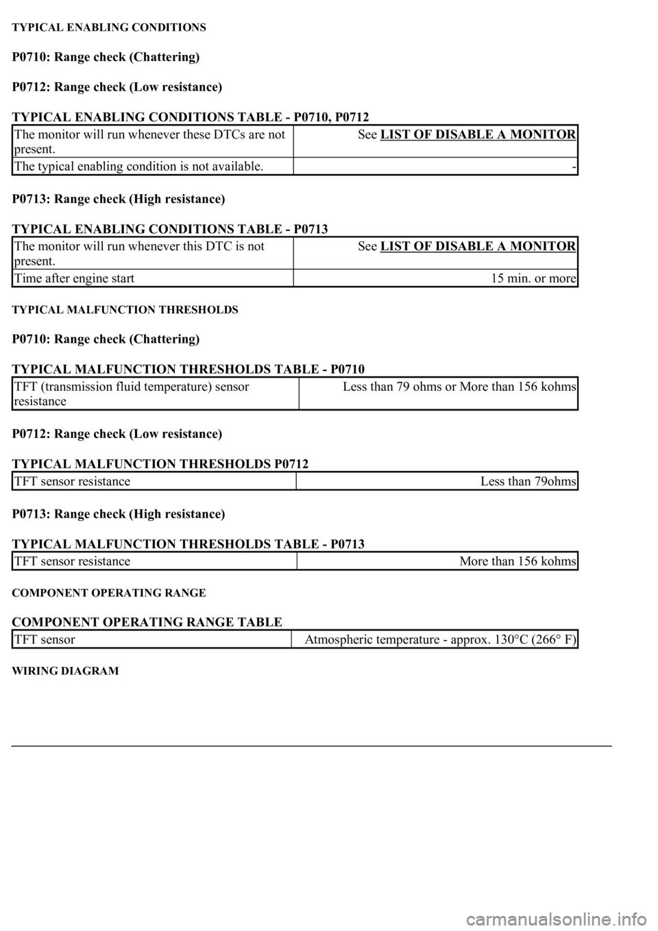
TYPICAL ENABLING CONDITIONS
P0710: Range check (Chattering)
P0712: Range check (Low resistance)
TYPICAL ENABLING CONDITIONS TABLE - P0710, P0712
P0713: Range check (High resistance)
TYPICAL ENABLING CONDITIONS TABLE - P0713
TYPICAL MALFUNCTION THRESHOLDS
P0710: Range check (Chattering)
TYPICAL MALFUNCTION THRESHOLDS TABLE - P0710
P0712: Range check (Low resistance)
TYPICAL MALFUNCTION THRESHOLDS P0712
P0713: Range check (High resistance)
TYPICAL MALFUNCTION THRESHOLDS TABLE - P0713
COMPONENT OPERATING RANGE
COMPONENT OPERATING RANGE TABLE
WIRING DIAGRAM
The monitor will run whenever these DTCs are not
present.See LIST OF DISABLE A MONITOR
The typical enabling condition is not available.-
The monitor will run whenever this DTC is not
present.See LIST OF DISABLE A MONITOR
Time after engine start15 min. or more
TFT (transmission fluid temperature) sensor
resistanceLess than 79 ohms or More than 156 kohms
TFT sensor resistanceLess than 79ohms
TFT sensor resistanceMore than 156 kohms
TFT sensorAtmospheric temperature - approx. 130°C (266° F)