Page 2474 of 4500
Fig. 44: Wiring Diagram - Stop Light Switch Circuit Malfunction
Courtesy of TOYOTA MOTOR SALES, U.S.A., INC.
INSPECTION PROCEDURE
1.READ VALUE ON HAND-HELD TESTER
a. Connect the han
d-held tester to the DLC3.
Page 2487 of 4500

This circuit uses CAN for communication. Therefore, if there are any malfunctions in the communication
circuit, one or more DTCs in the CAN communication system is/are output.
WIRING DIAGRAM
See WIRING DIAGRAM
.
INSPECTION PROCEDURE
See INSPECTION PROCEDURE
.
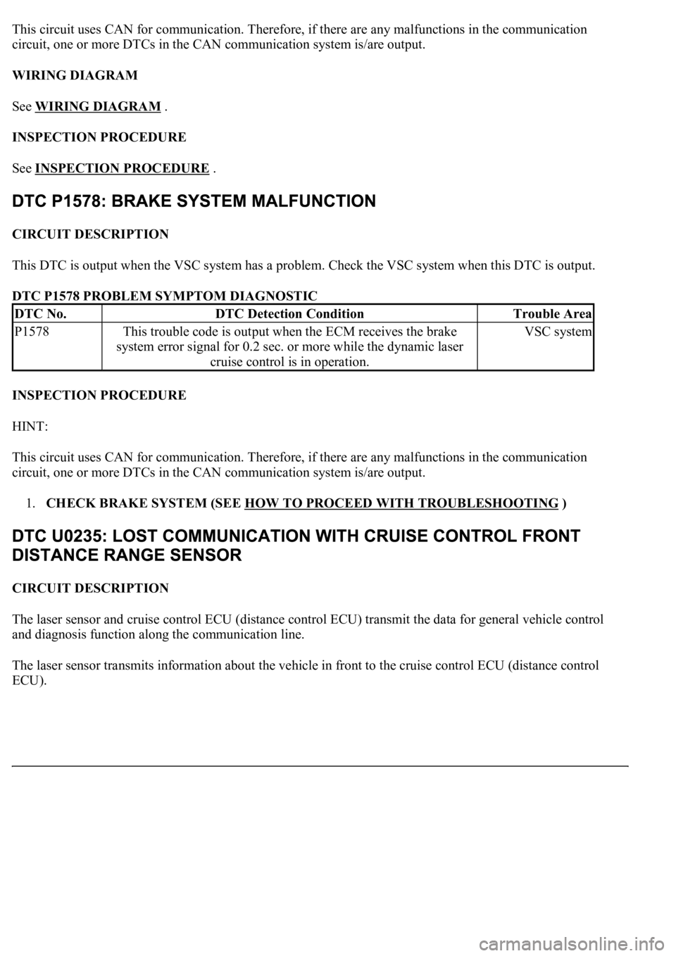
CIRCUIT DESCRIPTION
This DTC is output when the VSC system has a problem. Check the VSC system when this DTC is output.
DTC P1578 PROBLEM SYMPTOM DIAGNOSTIC
INSPECTION PROCEDURE
HINT:
This circuit uses CAN for communication. Therefore, if there are any malfunctions in the communication
circuit, one or more DTCs in the CAN communication system is/are output.
1.CHECK BRAKE SYSTEM (SEE HOW TO PROCEED WITH TROUBLESHOOTING
)
CIRCUIT DESCRIPTION
The laser sensor and cruise control ECU (distance control ECU) transmit the data for general vehicle control
and diagnosis function along the communication line.
The laser sensor transmits information about the vehicle in front to the cruise control ECU (distance control
ECU).
DTC No.DTC Detection ConditionTrouble Area
P1578This trouble code is output when the ECM receives the brake
system error signal for 0.2 sec. or more while the dynamic laser
cruise control is in operation.VSC system
Page 2488 of 4500
Fig. 55: DTC U0235 Problem Symptom Diagnostic Chart
Courtesy of TOYOTA MOTOR SALES, U.S.A., INC.
WIRING DIAGRAM
Fig. 56: Wiring Diagram
- Lost Communication With Cruise Control Front Distance Range Sensor
Courtesy of TOYOTA MOTOR SALES, U.S.A., INC.
INSPECTION PROCEDURE
1.CHECK WIRE HARNESS AND CONNECTOR (DISTANCE CONTROL ECU - LASER
SENSOR)
a. Disconnect the distance control ECU and laser sensor connectors.
b. Measure the resistance according to the value(s) in the table below.
Standard:
DISTANCE CONTROL ECU AND LASER SENSOR CONNECTOR TERMINALS
RESISTANCE SPECIFICATION
Tester connectionConditionSpecified value
D2-22 (LRDD) - L1-3 (LRDD)AlwaysBelow 1 ohms
D2-13 (IGB) - L1-5 (IGB)AlwaysBelow 1 ohms
D2-22 (LRDD) - Body groundAlways10 kohms or higher
D2-13 (IGB) - Body groundAlways10 kohms or higher
Page 2493 of 4500
Fig. 61: DTC U1102 Problem Symptom Diagnostic Chart
Courtesy of TOYOTA MOTOR SALES, U.S.A., INC.
WIRING DIAGRAM
Fig. 62: Wiring Diagram
- Lost Communication With Radar Sensor
Courtesy of TOYOTA MOTOR SALES, U.S.A., INC.
INSPECTION PROCEDURE
1.CHECK WIRE HARNESS AND CONNECTOR (DISTANCE CONTROL ECU - LASER
SENSOR)
a. Disconnect the distance control ECU and laser sensor connectors.
b. Measure the resistance according to the value(s) in the table below.
Standard:
DISTANCE CONTROL ECU AND LASER SENSOR CONNECTOR TERMINALS
RESISTANCE SPECIFICATION
Tester connectionConditionSpecified value
D2-23 (LRRD) - L1-4 (LRRD)AlwaysBelow 1 ohms
D2-13 (IGB) - L1-5 (IGB)AlwaysBelow 1 ohms
D2-23 (LRRD) - Body groundAlways10 kohms or higher
D2-13 (IGB) - Body groundAlways10 kohms or higher
Page 2500 of 4500
This circuit detects the yaw rate of the vehicle and transmits its signal to the skid control ECU and distance
control ECU.
Fig. 68: DTC U0123 Problem Symptom Diagnostic Chart
Courtesy of TOYOTA MOTOR SALES, U.S.A., INC.
INSPECTION PROCEDURE
HINT:
This circuit uses CAN for communication. Therefore, if there are any malfunctions in the communication
circuit, one or more DTCs in the CAN communication system is/are output.
1.GO TO CAN COMMUNICATION SYSTEM (SEE HOW TO PROCEED WITH
TROUBLESHOOTING )
CIRCUIT DESCRIPTION
This circuit provides power to operate the cruise control ECU (distance control ECU). The distance control
ECU determines the vehicle that you are following based on data from the laser sensor and then decides how
much acceleration and/or deceleration is needed to maintain the set distance. It also requests the skid control
ECU to apply braking and sound the buzzer.
WIRING DIAGRAM
Page 2501 of 4500
Fig. 69: Wiring Diagram - Distance Control ECU Power Source Circuit
Courtesy of TOYOTA MOTOR SALES, U.S.A., INC.
INSPECTION PROCEDURE
1.INSPECT CRUISE CONTROL ECU ASSY (DISTANCE CONTROL ECU)
a. Disconnect the cruise control ECU (distance control ECU) connector.
b. Measure the voltage according to the value(s) in the table below.
Standard:
CRUISE CONTROL ECU VOLTAGE RESISTANCE SPECIFICATION
Page 2503 of 4500

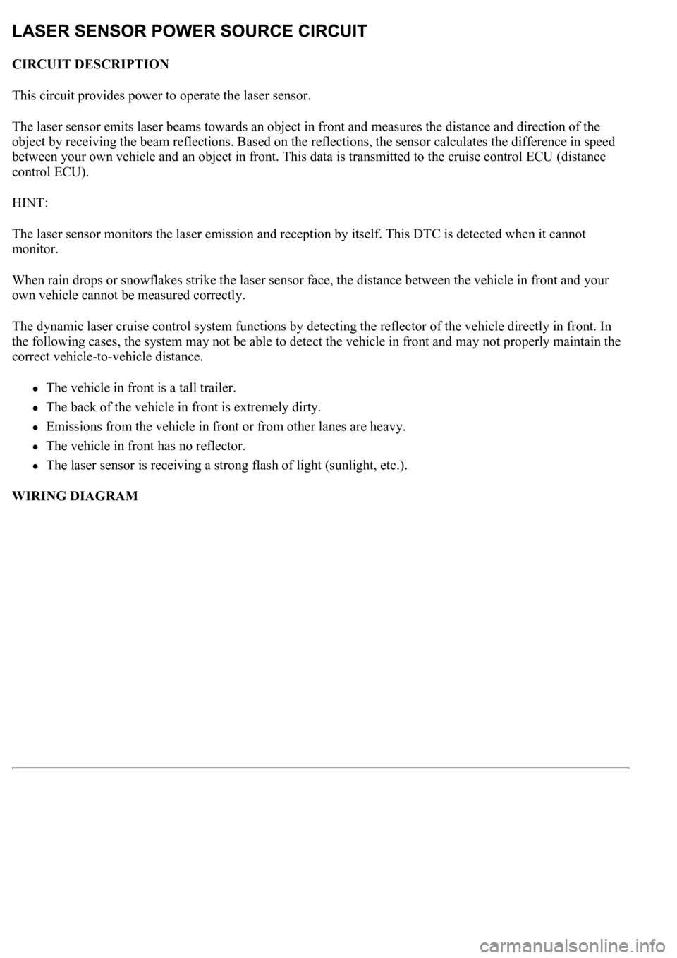
CIRCUIT DESCRIPTION
This circuit provides power to operate the laser sensor.
The laser sensor emits laser beams towards an object in front and measures the distance and direction of the
object by receiving the beam reflections. Based on the reflections, the sensor calculates the difference in speed
between your own vehicle and an object in front. This data is transmitted to the cruise control ECU (distance
control ECU).
HINT:
The laser sensor monitors the laser emission and reception by itself. This DTC is detected when it cannot
monitor.
When rain drops or snowflakes strike the laser sensor face, the distance between the vehicle in front and your
own vehicle cannot be measured correctly.
The dynamic laser cruise control system functions by detecting the reflector of the vehicle directly in front. In
the following cases, the system may not be able to detect the vehicle in front and may not properly maintain the
correct vehicle-to-vehicle distance.
The vehicle in front is a tall trailer.
The back of the vehicle in front is extremely dirty.
Emissions from the vehicle in front or from other lanes are heavy.
The vehicle in front has no reflector.
The laser sensor is receiving a strong flash of light (sunlight, etc.).
WIRING DIAGRAM
Page 2504 of 4500
Fig. 71: Wiring Diagram - Laser Sensor Power Source Circuit
Courtesy of TOYOTA MOTOR SALES, U.S.A., INC.
INSPECTION PROCEDURE
1.INSPECT LASER SENSOR
a. Disconnect the laser sensor connector.
b. Measure the voltage according to the value(s) in the table below.
Standard:
LASER SENSOR CONNECTOR TERMINALS VOLTAGE SPECIFICATION
Tester connectionConditionSpecified value
L1-5 (IGB) - Body groundIgnition SW ON10 to 14 V