Page 2510 of 4500
internal contact point of the cruise control main switch is turned on with the switch operation. The ECM then
reads the resistance value that has been changed by the switch operation to control MODE, SET, COAST,
RESUME, ACCEL and CANCEL.
The dynamic laser cruise control system has two cruise control modes: the constant speed control mode and
vehicle-to-vehicle distance control mode.
The vehicle-to-vehicle distance control mode is always selected when starting up the dynamic laser cruise
control system.
The operation of the constant speed control mode is the same as that for the conventional type cruise
control system.
WIRING DIAGRAM
Fig. 77: Wiring Diagram
- Cruise Control Switch Circuit
Courtesy of TOYOTA MOTOR SALES, U.S.A., INC.
INSPECTION PROCEDURE
1.READ VALUE OF HAND-HELD TESTER
Page 2521 of 4500
malfunctions in this circuit, check for DTCs in the CAN communication and multiplex communication systems.
When the wiper is in the LO or HI mode, the dynamic laser cruise control is automatically cancelled and goes
into the standby mode. (In INT (intermittent operation) mode, the laser cruise control is not cancelled.)
INSPECTION PROCEDURE
1.INSPECT WIPER AND WASHER SYSTEM (SEE INSPECTION
)
OK:
Wiper function is normal.
NG: GO TO WIPER AND WASHER SYSTEM (SEE HOW TO PROCEED WITH
TROUBLESHOOTING )
OK: PROCEED TO NEXT CIRCUIT INSPECTION SHOWN IN DIAGNOSTIC TROUBLE
CODE CHART
CIRCUIT DESCRIPTION
This circuit outputs trouble codes on the multi-information display in the combination meter when terminals TC
and CG of the DLC3 are connected.
WIRING DIAGRAM
Fig. 84: Wiring Diagram
- Diagnosis Circuit
Page 2529 of 4500
Fig. 3: Wiring Diagram - Dynamic Radar Cruise Control System
Courtesy of TOYOTA MOTOR SALES, U.S.A., INC.
Page 2573 of 4500
CIRCUIT DESCRIPTION
SEE CIRCUIT DESCRIPTION
.
Fig. 44: DTC P0500 And P0503 Problem Symptom Diagnostic Chart
Courtesy of TOYOTA MOTOR SALES, U.S.A., INC.
WIRING DIAGRAM
SEE WIRING DIAGRAM
.
INSPECTION PROCEDURE
SEE INSPECTION PROCEDURE
.
CIRCUIT DESCRIPTION
When the brake pedal is depressed, the stop lamp switch assy sends a signal to the ECM. When the ECM
receives this signal, it cancels the cruise control.
The fail-safe function operates to enable normal driving even if there is a malfunction in the stop lamp signal
circuit.
The cancel condition occurs when positive battery voltage is applied to terminal STP.
When the brake is applied, battery positive voltage is normally applied to terminal STP of the ECM through the
STOP fuse and the stop lamp switch ass
y, and the ECM turns the cruise control off.
Page 2574 of 4500
Fig. 45: DTC P0571 Problem Symptom Diagnostic Chart
Courtesy of TOYOTA MOTOR SALES, U.S.A., INC.
WIRING DIAGRAM
Page 2575 of 4500
Fig. 46: Wiring Diagram - Stop Light Switch Circuit Malfunction
Courtesy of TOYOTA MOTOR SALES, U.S.A., INC.
INSPECTION PROCEDURE
1.READ VALUE ON HAND-HELD TESTER
a. Connect the han
d-held tester to the DLC3.
Page 2588 of 4500

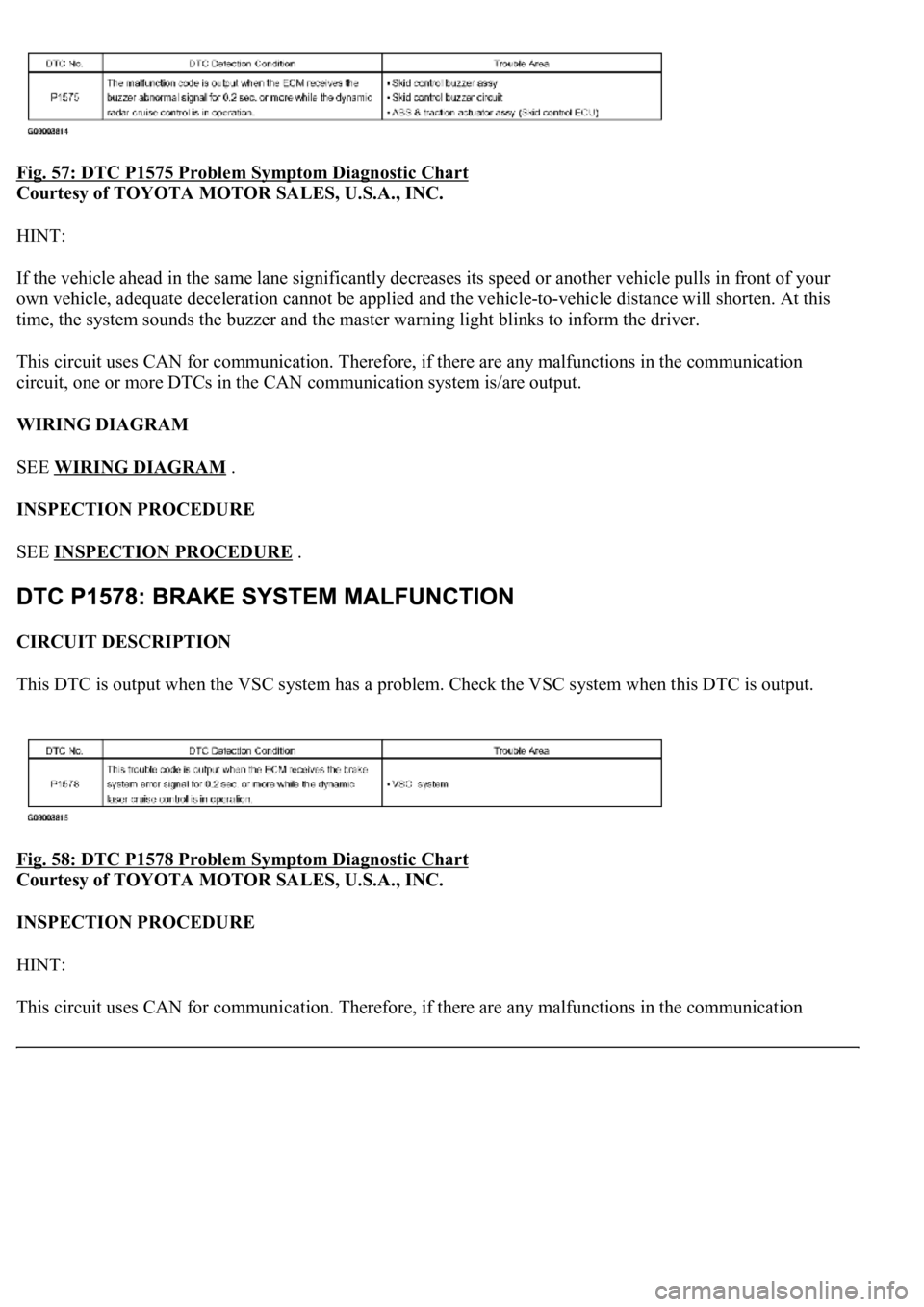
Fig. 57: DTC P1575 Problem Symptom Diagnostic Chart
Courtesy of TOYOTA MOTOR SALES, U.S.A., INC.
HINT:
If the vehicle ahead in the same lane significantly decreases its speed or another vehicle pulls in front of your
own vehicle, adequate deceleration cannot be applied and the vehicle-to-vehicle distance will shorten. At this
time, the system sounds the buzzer and the master warning light blinks to inform the driver.
This circuit uses CAN for communication. Therefore, if there are any malfunctions in the communication
circuit, one or more DTCs in the CAN communication system is/are output.
WIRING DIAGRAM
SEE WIRING DIAGRAM
.
INSPECTION PROCEDURE
SEE INSPECTION PROCEDURE
.
CIRCUIT DESCRIPTION
This DTC is output when the VSC system has a problem. Check the VSC system when this DTC is output.
Fig. 58: DTC P1578 Problem Symptom Diagnostic Chart
Courtesy of TOYOTA MOTOR SALES, U.S.A., INC.
INSPECTION PROCEDURE
HINT:
This circuit uses CAN for communication. Therefore, if there are an
y malfunctions in the communication
Page 2589 of 4500
circuit, one or more DTCs in the CAN communication system is/are output.
1.CHECK BRAKE SYSTEM (SEE HOW TO PROCEED WITH TROUBLESHOOTING
)
CIRCUIT DESCRIPTION
The Millimeter wave radar sensor and cruise control ECU (distance control ECU) transmit the data for general
vehicle control and diagnosis function along the communication line.
The Millimeter wave radar sensor transmits information about the vehicle in front to the cruise control ECU
(distance control ECU).
Fig. 59: DTC U0235 Problem Symptom Diagnostic Chart
Courtesy of TOYOTA MOTOR SALES, U.S.A., INC.
WIRING DIAGRAM
Fig. 60: Wiring Diagram
- Lost Communication With Cruise Control Front Distance Range Sensor
Courtesy of TOYOTA MOTOR SALES, U.S.A., INC.
INSPECTION PROCEDURE
1.CHECK WIRE HARNESS AND CONNECTOR (DISTANCE CONTROL ECU - MILLIMETER