Page 593 of 4500

c. Check the operating sound of the exhaust solenoid valve.
OK:
It should make an operating sound (click).
HINT:
When a malfunction is found in the exhaust solenoid valve, replace the height control compressor assy.
NG: REPLACE HEIGHT CONTROL COMPRESSOR ASSY (SEE REPLACEMENT
)
OK:Go to next step
6.INSPECT HEIGHT CONTROL SENSOR LINK SUB-ASSY
a. Inspect and adjust the height control sensor link sub-assy (see ON
-VEHICLE INSPECTION ).
NG: REPLACE HEIGHT CONTROL SENSOR LINK SUB-ASSY
OK: CHECK AND REPAIR OR REPLACE PARTS
Air tube is clogged (see ON-VEHICLE INSPECTION ).
Compressor is faulty (see REPLACEMENT ).
Height control sensor sub-assy is faulty (see REPLACEMENT - HEIGHT CONTROL
SENSOR SUB-ASSY FRONT , REPLACEMENT - HEIGHT CONTROL SENSOR SUB-
ASSY REAR LH ).
Foreign material in the height control solenoid valve and/or exhaust solenoid valve (see
REPLACEMENT
- HEIGHT CONTROL COMPRESSOR ASSY , REPLACEMENT -
HEIGHT CONTROL VALVE SUB
-ASSY NO.1 , REPLACEMENT - HEIGHT CONTROL
VALVE SUB-ASSY NO.2 ).
Suspension control ECU malfunction (see REPLACEMENT ).
CIRCUIT DESCRIPTION
Page 596 of 4500
Fig. 111: Identifying Rear Height Control Sensor Sub-Assy Connector Terminals
Courtesy of TOYOTA MOTOR SALES, U.S.A., INC.
OK:Go to next step
3.CHECK HARNESS AND CONNECTOR (SUSPENSION CONTROL ECU - BODY GROUND)
(SEE ELECTRONIC CIRCUIT INSPECTION PROCEDURE
)
a. Turn the ignition switch off.
b. Disconnect the suspension control ECU A21 connector.
c. Measure the resistance according to the value (s) in the table below.
TESTER CONNECTION STANDARD SPECIFIED CONDITION
NG: REPAIR OR REPLACE HARNESS OR CONNECTOR
OK:Go to next step
Tester ConnectionSpecified Condition
A21-23 (SBL3) - Body ground10 Kohms or higher
Page 605 of 4500
Fig. 120: Identifying Suspension Control ECU Connector Terminals
Courtesy of TOYOTA MOTOR SALES, U.S.A., INC.
NG: REPAIR OR REPLACE HARNESS OR CONNECTOR
OK: REPLACE SUSPENSION CONTROL ECU (SEE REPLACEMENT
)
CIRCUIT DESCRIPTION
The speed sensors monitors the speed of the wheels, and sends an appropriate speed signals to the suspension
control ECU through the brake actuator assy (skid control ECU).
If trouble occurs in either the right rear speed sensor or left rear speed sensor, DTC (C1776) is output.
Page 1231 of 4500
Dynamic
Radar/Laser
Cruise
(Maintains
vehicle-to-
vehicle
distance)
Tx
RxTx Rx Tx Rx
Vehicl
Vehi
dista
n
control
not op
e
Back
Monitor
(Exterior
view from
rear of
vehicle is
displayed
while
reversing)
Tx Rx Back m
onl
Air
Suspension
Control
(Controls
suspension
properly
based on
vehicle
conditions)
TxTx Rx Control
Meter
Display
(Displays
operation
condition
and DTCs)
TxTx RxTx
Lamp
not co
m
or remai
Pre -
collision
Safety (Skid
control ECU
brings BA in
standby
mode and
seat belt is
fastened by
seat belt
control ECU
when
distance
control ECU
determines
that collision
Rx Tx RxPre-col
l
safety sy
does
oper
a
Page 2045 of 4500

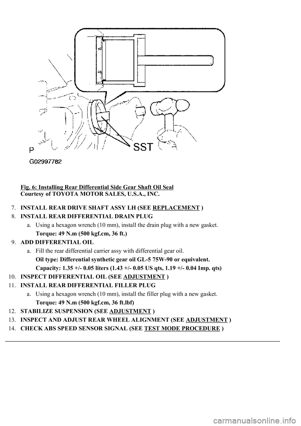
Fig. 6: Installing Rear Differential Side Gear Shaft Oil Seal
Courtesy of TOYOTA MOTOR SALES, U.S.A., INC.
7.INSTALL REAR DRIVE SHAFT ASSY LH (SEE REPLACEMENT
)
8.INSTALL REAR DIFFERENTIAL DRAIN PLUG
a. Using a hexagon wrench (10 mm), install the drain plug with a new gasket.
Torque: 49 N.m (500 kgf.cm, 36 ft.)
9.ADD DIFFERENTIAL OIL
a. Fill the rear differential carrier assy with differential gear oil.
Oil type: Differential synthetic gear oil GL-5 75W-90 or equivalent.
<00260044005300440046004c0057005c001d000300140011001600180003000e00120010000300130011001300180003004f004c00570048005500560003000b00140011001700160003000e00120010000300130011001300180003003800360003005400
570056000f0003001400110014001c0003000e001200100003[0.04 Imp. qts)
10.INSPECT DIFFERENTIAL OIL (SEE ADJUSTMENT
)
11.INSTALL REAR DIFFERENTIAL FILLER PLUG
a. Using a hexagon wrench (10 mm), install the filler plug with a new gasket.
Torque: 49 N.m (500 kgf.cm, 36 ft.lbf)
12.STABILIZE SUSPENSION (SEE ADJUSTMENT
)
13.INSPECT AND ADJUST REAR WHEEL ALIGNMENT (SEE ADJUSTMENT
)
14.CHECK ABS SPEED SENSOR SIGNAL (SEE TEST MODE PROCEDURE
)
Page 2046 of 4500

OVERHAUL
HINT:
See COMPONENTS
1.REMOVE REAR WHEEL
2.REMOVE EXHAUST PIPE ASSY (SEE REPLACEMENT
)
3.REMOVE FRONT FLOOR HEAT INSULATOR NO.1 (SEE OVERHAUL
)
4.REMOVE PROPELLER SHAFT HEAT INSULATOR (SEE OVERHAUL
)
5.REMOVE PROPELLER W/CENTER BEARING SHAFT ASSY (SEE OVERHAUL
)
6.REMOVE REAR DIFFERENTIAL FILLER PLUG
a. Using a hexagon wrench (10 mm), remove the filler plug and gasket.
7.REMOVE REAR DIFFERENTIAL DRAIN PLUG
a. Using a hexagon wrench (10 mm), remove the drain plug and gasket.
b. Drain the differential oil.
8.REMOVE REAR DRIVE SHAFT ASSY LH (SEE REPLACEMENT
)
9.REMOVE REAR DRIVE SHAFT ASSY RH
HINT:
Removal procedure of the RH side is the same as that of the LH side.
10.REMOVE STABILIZER BAR REAR (SEE REPLACEMENT
)
HINT:
Perform this procedure only when the rear differential mount cushion should be changed.
11.REMOVE HEIGHT CONTROL VALVE SUB-ASSY NO.2 (W/ AIR SUSPENSION) (SEE
REPLACEMENT
)
HINT:
Perform this procedure only when the rear differential mount cushion should be changed.
12.REMOVE DIFFERENTIAL CARRIER ASSY REAR
a. Support the differential carrier with a jack and wooden block.
Page 2176 of 4500
Fig. 136: Installing Bolts
Courtesy of TOYOTA MOTOR SALES, U.S.A., INC.
63.INSTALL HEIGHT CONTROL VALVE SUB-ASSY NO.2 (W/ AIR SUSPENSION) (SEE
REPLACEMENT
)
HINT:
Perform this operation only when the rear differential mount cushion is replaced.
64.INSTALL STABILIZER BAR REAR (SEE REPLACEMENT
)
HINT:
Perform this operation only when the rear differential mount cushion is replaced.
65.INSTALL REAR DIFFERENTIAL DRAIN PLUG
a. Using a hexagon wrench (10 mm), install the drain plug with a new gasket.
Torque: 49 N.m (500 kgf.cm, 36 ft.lbf)
66.ADD DIFFERENTIAL OIL
Page 2177 of 4500

a. Fill the rear differential carrier assy with differential gear oil equivalent.
Oil type: Differential synthetic gear oil GL-5 75W-90 or equivalent
Capacity: 1.35 +/- 0.05 liters (1.43 +/- 0.05 US qts, 1.19 +/- 0.04 Imp. qts)
67.INSPECT DIFFERENTIAL OIL (SEE ADJUSTMENT
)
68.INSTALL REAR DIFFERENTIAL FILLER PLUG
a. Using a hexagon wrench (10 mm), install the filler plug with a new gasket.
Torque: 49 N.m (500 kgf.cm, 36 ft.lbf)
69.INSTALL REAR DRIVE SHAFT ASSY LH (SEE REPLACEMENT
)
70.INSTALL REAR DRIVE SHAFT ASSY RH
HINT:
Installation procedure of the RH side is the same as that of the LH side.
71.INSTALL FRONT FLOOR HEAT INSULATOR NO.1
a. Install the front floor heat insulator No.1 with the 4 bolts.
Torque: 5.4 N.m (55 kgf.cm, 48 in..lbf)
72.INSTALL REAR WHEEL
a. Install the rear wheel with the 5 nuts.
Torque: 103 N.m (1,050 kgf.cm, 76 ft.lbf)
73. Install the ornament with the 10 bolts.
Torque: 20 N.m (204 kgf.cm, 15 ft.lbf)
74.INSTALL PROPELLER W/CENTER BEARING SHAFT ASSY (SEE OVERHAUL
)
75.FULLY TIGHTEN CENTER SUPPORT BEARING ASSY NO.1 (SEE OVERHAUL
)
SST 09922-10010
76.INSPECT AND ADJUST NO.2 AND NO.3 JOINT ANGLE (SEE OVERHAUL
)
77.INSTALL PROPELLER SHAFT HEAT INSULATOR (SEE OVERHAUL
)
78.INSTALL EXHAUST PIPE ASSY (SEE REPLACEMENT
)
79.INSTALL OXYGEN SENSOR (SEE REPLACEMENT
)
80.INSPECT AND ADJUST REAR WHEEL ALIGNMENT (SEE ADJUSTMENT
)
81.ADJUST VEHICLE HEIGHT (W/ AIR SUSPENSION) (SEE ON
-VEHICLE INSPECTION )
82.INSPECT HEADLIGHT AIM ONLY (SEE ADJUSTMENT
)
83.CHECK ABS SPEED SENSOR SIGNAL (SEE TEST MODE PROCEDURE
)
84.INSPECT AIR LEAK (W/ AIR SUSPENSION) (SEE REPLACEMENT
)
HINT:
Perform this operation onl
y when the rear differential mount cushion is replaced.