Page 1861 of 4500
Fig. 10: Measuring Resistance Relay
Courtesy of TOYOTA MOTOR SALES, U.S.A., INC.
2.INSPECT ECT SWITCH
a. Measure the resistance of the switch.
STANDARD SPECIFICATION
If the result is not as specified, replace the switch.
TemperatureSpecified Condition
Above 98° C (208° F)Below 1 Q
Below 88° C (190° F)10 kQ or higher
Page 1913 of 4500
Fig. 9: Checking RES (RESUME) Function
Courtesy of TOYOTA MOTOR SALES, U.S.A., INC.
If a normal system code is displayed during the DTC check but the problem still occurs, check the circuits for
each problem symptom in the order given in the table below and proceed to the relevant troubleshooting page.
HINT:
Inspect the "Fuse" and "Relay" before confirming the suspected areas as shown in the chart below.
Inspect each malfunction circuit in numerical order for the correspondin
g symptom.
Page 1932 of 4500

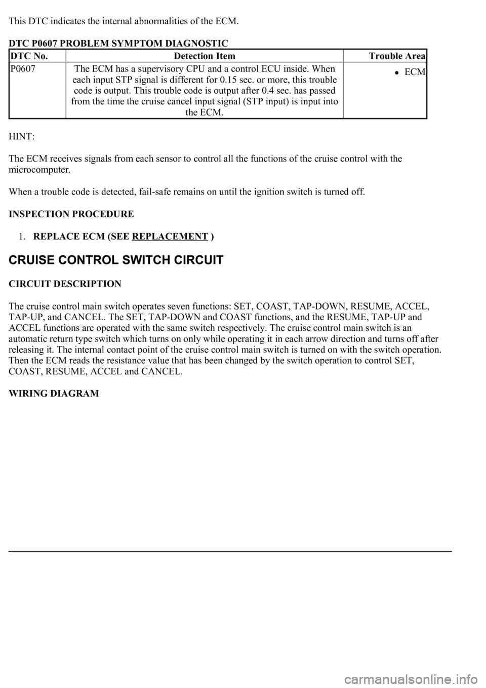
This DTC indicates the internal abnormalities of the ECM.
DTC P0607 PROBLEM SYMPTOM DIAGNOSTIC
HINT:
The ECM receives signals from each sensor to control all the functions of the cruise control with the
microcomputer.
When a trouble code is detected, fail-safe remains on until the ignition switch is turned off.
INSPECTION PROCEDURE
1.REPLACE ECM (SEE REPLACEMENT
)
CIRCUIT DESCRIPTION
The cruise control main switch operates seven functions: SET, COAST, TAP-DOWN, RESUME, ACCEL,
TAP-UP, and CANCEL. The SET, TAP-DOWN and COAST functions, and the RESUME, TAP-UP and
ACCEL functions are operated with the same switch respectively. The cruise control main switch is an
automatic return type switch which turns on only while operating it in each arrow direction and turns off after
releasing it. The internal contact point of the cruise control main switch is turned on with the switch operation.
Then the ECM reads the resistance value that has been changed by the switch operation to control SET,
COAST, RESUME, ACCEL and CANCEL.
WIRING DIAGRAM
DTC No.Detection ItemTrouble Area
P0607The ECM has a supervisory CPU and a control ECU inside. When
each input STP signal is different for 0.15 sec. or more, this trouble
code is output. This trouble code is output after 0.4 sec. has passed
from the time the cruise cancel input signal (STP input) is input into
the ECM.ECM
Page 2182 of 4500

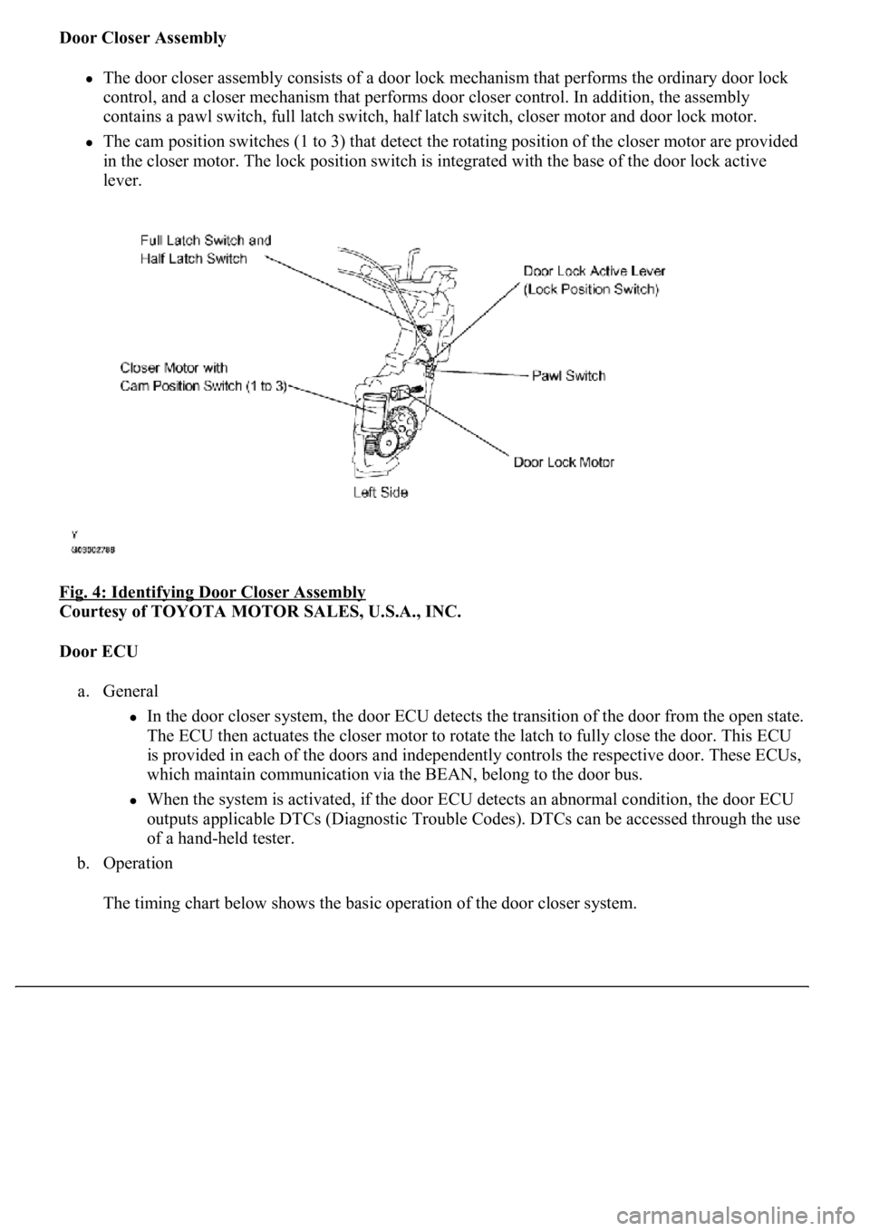
Door Closer Assembly
The door closer assembly consists of a door lock mechanism that performs the ordinary door lock
control, and a closer mechanism that performs door closer control. In addition, the assembly
contains a pawl switch, full latch switch, half latch switch, closer motor and door lock motor.
The cam position switches (1 to 3) that detect the rotating position of the closer motor are provided
<004c005100030057004b004800030046004f0052005600480055000300500052005700520055001100030037004b00480003004f00520046004e0003005300520056004c0057004c0052005100030056005a004c00570046004b0003004c00560003004c00
5100570048004a005500440057004800470003005a004c0057[h the base of the door lock active
lever.
Fig. 4: Identifying Door Closer Assembly
Courtesy of TOYOTA MOTOR SALES, U.S.A., INC.
Door ECU
a. General
In the door closer system, the door ECU detects the transition of the door from the open state.
The ECU then actuates the closer motor to rotate the latch to fully close the door. This ECU
is provided in each of the doors and independently controls the respective door. These ECUs,
which maintain communication via the BEAN, belong to the door bus.
When the system is activated, if the door ECU detects an abnormal condition, the door ECU
outputs applicable DTCs (Diagnostic Trouble Codes). DTCs can be accessed through the use
of a hand-held tester.
b. Operation
The timin
g chart below shows the basic operation of the door closer system.
Page 2341 of 4500
Fig. 36: Aligning Matchmarks
Courtesy of TOYOTA MOTOR SALES, U.S.A., INC.
f. If using a new propeller shaft (w/phasemarks):
Install the propeller shaft phasemarks and differential/transmission phasemarks so that their
respective alignment phasemarks match.
If the propeller shaft phasemarks and differential/transmission phasemarks do not align, install the
propeller shaft and differential alignment phasemarks as close together as possible.
g.If using a new propeller shaft (w/o phase marks): Install the propeller shaft.
Page 2450 of 4500
Fig. 18: Multi-Information Display Chart On Combination Meter
Courtesy of TOYOTA MOTOR SALES, U.S.A., INC.
HINT:
The indication is immediately set to "LONG" each time the engine is started.
If a normal system code is displayed during the DTC check but the problem still occurs, check the suspected
areas for each problem symptom in the order given in the table below and proceed to the relevant
troubleshooting page.
HINT:
Inspect the "Fuse" and "Relay" before confirming the suspected areas as shown in the chart below. Inspect each
suspected area for the correspondin
g symptom in numerical order.
Page 2485 of 4500

NG: REPLACE CRUISE CONTROL ECU ASSY (SEE REPLACEMENT )
OK: SYSTEM OK
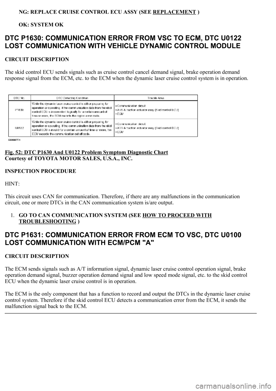
CIRCUIT DESCRIPTION
The skid control ECU sends signals such as cruise control cancel demand signal, brake operation demand
response signal from the ECM, etc. to the ECM when the dynamic laser cruise control system is in operation.
Fig. 52: DTC P1630 And U0122 Problem Symptom Diagnostic Chart
Courtesy of TOYOTA MOTOR SALES, U.S.A., INC.
INSPECTION PROCEDURE
HINT:
This circuit uses CAN for communication. Therefore, if there are any malfunctions in the communication
circuit, one or more DTCs in the CAN communication system is/are output.
1.GO TO CAN COMMUNICATION SYSTEM (SEE HOW TO PROCEED WITH
TROUBLESHOOTING )
CIRCUIT DESCRIPTION
The ECM sends signals such as A/T information signal, dynamic laser cruise control operation signal, brake
operation demand signal, buzzer operation demand signal and low speed mode signal, etc. to the skid control
ECU when the dynamic laser cruise control is in operation.
<0037004b004800030028002600300003004c005600030057004b0048000300520051004f005c000300460052005000530052005100480051005700030057004b004400570003004b0044005600030044000300490058005100460057004c00520051000300
57005200030055004800460052005500470003004400510047[ output the DTCs in the dynamic laser cruise
control system. Therefore if the skid control ECU detects a communication error from the ECM, it sends the
malfunction signal back to the ECM.
Page 2550 of 4500
Fig. 18: Multi-Information Display Chart On Combination Meter
Courtesy of TOYOTA MOTOR SALES, U.S.A., INC.
HINT:
The indication is immediately set to "LONG" each time the engine is started.
If a normal system code is displayed during the DTC check but the problem still occurs, check the suspected
areas for each problem symptom in the order given in the table below and proceed to the relevant
troubleshooting page.
HINT:
Inspect the "Fuse" and "Relay" before confirming the suspected areas as shown in the Fig. 19
below. Inspect
each suspected area for the correspondin
g symptom in numerical order.