Page 726 of 4500
a. With "CHEC" or "ECHN" being displayed, press the preset switch "2" to go to the detailed
information mode.
b. Press the "SEEK TRACK" switch to display the "System check result (SYS)" and "Diagnostic
memory response (CODE)".
Fig. 21: Identifying Seek Track Switch To Display
Courtesy of TOYOTA MOTOR SALES, U.S.A., INC.
Page 818 of 4500
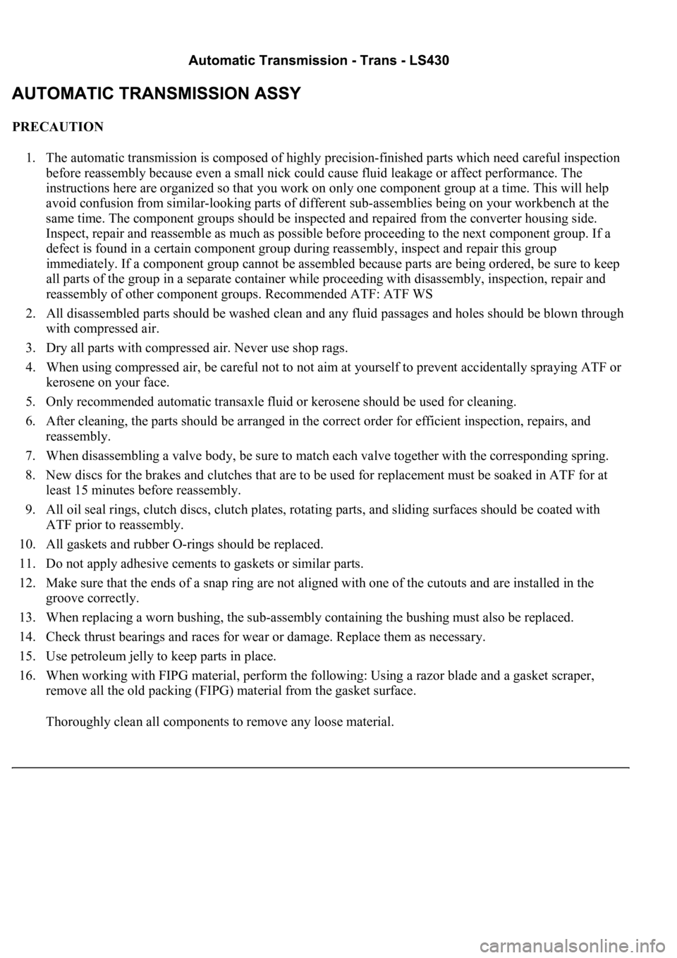
PRECAUTION
1. The automatic transmission is composed of highly precision-finished parts which need careful inspection
before reassembly because even a small nick could cause fluid leakage or affect performance. The
instructions here are organized so that you work on only one component group at a time. This will help
avoid confusion from similar-looking parts of different sub-assemblies being on your workbench at the
same time. The component groups should be inspected and repaired from the converter housing side.
Inspect, repair and reassemble as much as possible before proceeding to the next component group. If a
defect is found in a certain component group during reassembly, inspect and repair this group
immediately. If a component group cannot be assembled because parts are being ordered, be sure to keep
all parts of the group in a separate container while proceeding with disassembly, inspection, repair and
reassembly of other component groups. Recommended ATF: ATF WS
2. All disassembled parts should be washed clean and any fluid passages and holes should be blown through
with compressed air.
3. Dry all parts with compressed air. Never use shop rags.
4. When using compressed air, be careful not to not aim at yourself to prevent accidentally spraying ATF or
kerosene on your face.
5. Only recommended automatic transaxle fluid or kerosene should be used for cleaning.
6. After cleaning, the parts should be arranged in the correct order for efficient inspection, repairs, and
reassembly.
7. When disassembling a valve body, be sure to match each valve together with the corresponding spring.
8. New discs for the brakes and clutches that are to be used for replacement must be soaked in ATF for at
least 15 minutes before reassembly.
9. All oil seal rings, clutch discs, clutch plates, rotating parts, and sliding surfaces should be coated with
ATF prior to reassembly.
10. All gaskets and rubber O-rings should be replaced.
11. Do not apply adhesive cements to gaskets or similar parts.
12. Make sure that the ends of a snap ring are not aligned with one of the cutouts and are installed in the
groove correctly.
13. When replacing a worn bushing, the sub-assembly containing the bushing must also be replaced.
14. Check thrust bearings and races for wear or damage. Replace them as necessary.
15. Use petroleum jelly to keep parts in place.
16. When working with FIPG material, perform the following: Using a razor blade and a gasket scraper,
remove all the old packing (FIPG) material from the gasket surface.
Thoroughly clean all components to remove any loose material.
Page 1642 of 4500
OK: Go to next step
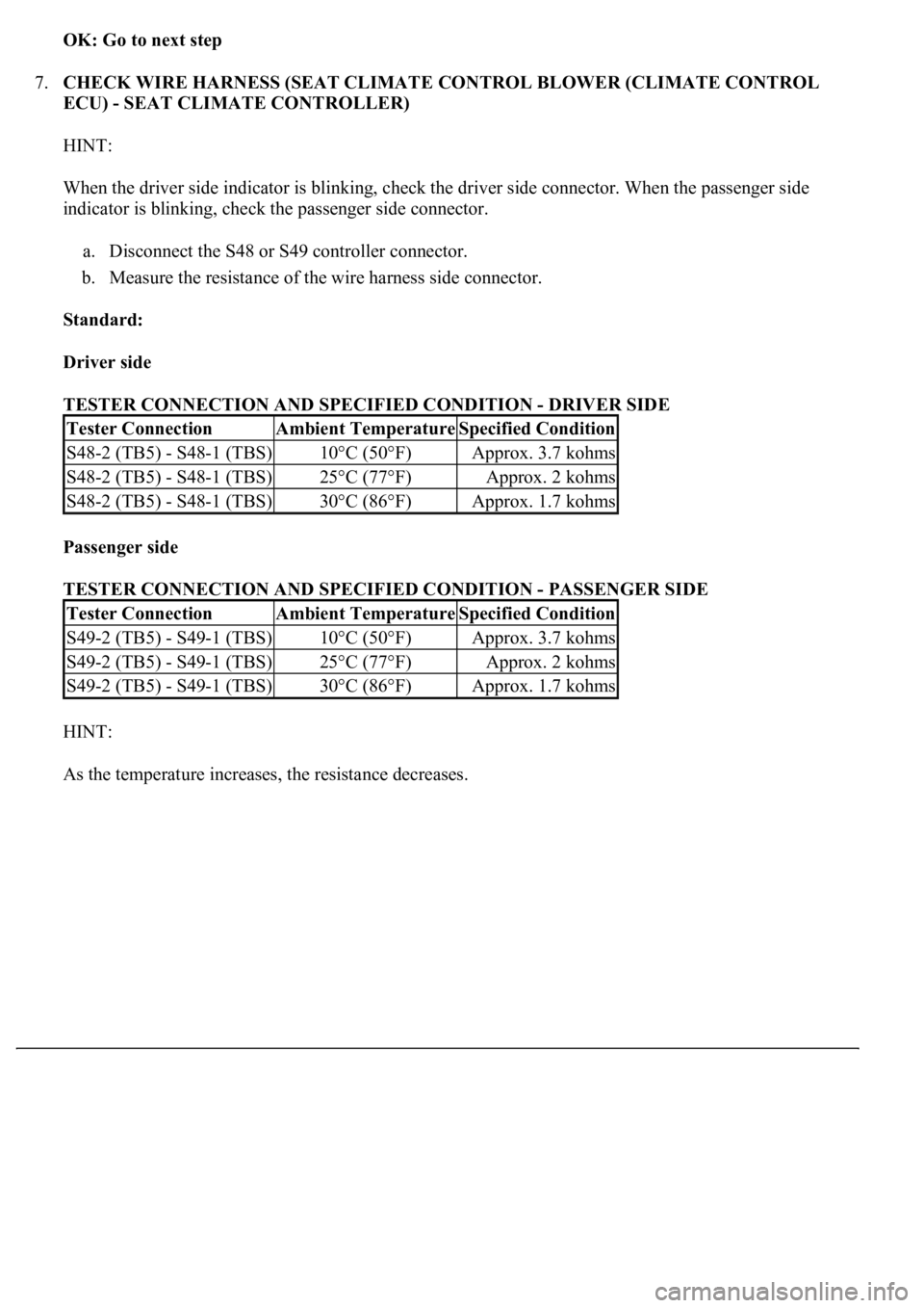
7.CHECK WIRE HARNESS (SEAT CLIMATE CONTROL BLOWER (CLIMATE CONTROL
ECU) - SEAT CLIMATE CONTROLLER)
HINT:
When the driver side indicator is blinking, check the driver side connector. When the passenger side
indicator is blinking, check the passenger side connector.
a. Disconnect the S48 or S49 controller connector.
b. Measure the resistance of the wire harness side connector.
Standard:
Driver side
TESTER CONNECTION AND SPECIFIED CONDITION - DRIVER SIDE
Passenger side
TESTER CONNECTION AND SPECIFIED CONDITION - PASSENGER SIDE
HINT:
As the temperature increases, the resistance decreases.
Tester ConnectionAmbient TemperatureSpecified Condition
S48-2 (TB5) - S48-1 (TBS)10°C (50°F)Approx. 3.7 kohms
S48-2 (TB5) - S48-1 (TBS)25°C (77°F)Approx. 2 kohms
S48-2 (TB5) - S48-1 (TBS)30°C (86°F)Approx. 1.7 kohms
Tester ConnectionAmbient TemperatureSpecified Condition
S49-2 (TB5) - S49-1 (TBS)10°C (50°F)Approx. 3.7 kohms
S49-2 (TB5) - S49-1 (TBS)25°C (77°F)Approx. 2 kohms
S49-2 (TB5) - S49-1 (TBS)30°C (86°F)Approx. 1.7 kohms
Page 1651 of 4500
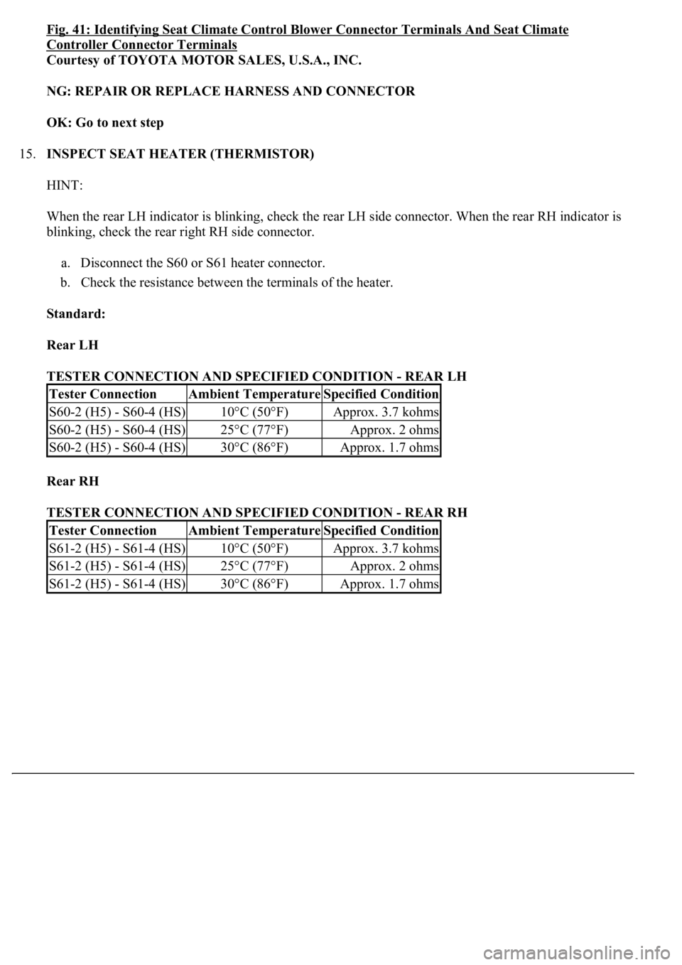
Fig. 41: Identifying Seat Climate Control Blower Connector Terminals And Seat Climate
Controller Connector Terminals
Courtesy of TOYOTA MOTOR SALES, U.S.A., INC.
NG: REPAIR OR REPLACE HARNESS AND CONNECTOR
OK: Go to next step
15.INSPECT SEAT HEATER (THERMISTOR)
HINT:
When the rear LH indicator is blinking, check the rear LH side connector. When the rear RH indicator is
blinking, check the rear right RH side connector.
a. Disconnect the S60 or S61 heater connector.
b. Check the resistance between the terminals of the heater.
Standard:
Rear LH
TESTER CONNECTION AND SPECIFIED CONDITION - REAR LH
Rear RH
TESTER CONNECTION AND SPECIFIED CONDITION - REAR RH
Tester ConnectionAmbient TemperatureSpecified Condition
S60-2 (H5) - S60-4 (HS)10°C (50°F)Approx. 3.7 kohms
S60-2 (H5) - S60-4 (HS)25°C (77°F)Approx. 2 ohms
S60-2 (H5) - S60-4 (HS)30°C (86°F)Approx. 1.7 ohms
Tester ConnectionAmbient TemperatureSpecified Condition
S61-2 (H5) - S61-4 (HS)10°C (50°F)Approx. 3.7 kohms
S61-2 (H5) - S61-4 (HS)25°C (77°F)Approx. 2 ohms
S61-2 (H5) - S61-4 (HS)30°C (86°F)Approx. 1.7 ohms
Page 1660 of 4500
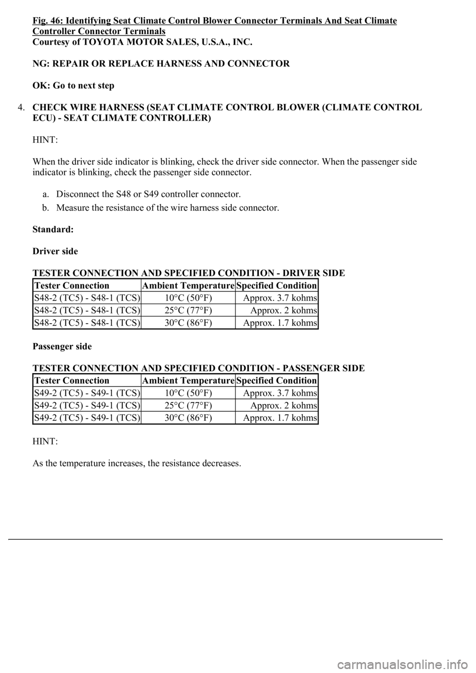
Fig. 46: Identifying Seat Climate Control Blower Connector Terminals And Seat Climate
Controller Connector Terminals
Courtesy of TOYOTA MOTOR SALES, U.S.A., INC.
NG: REPAIR OR REPLACE HARNESS AND CONNECTOR
OK: Go to next step
4.CHECK WIRE HARNESS (SEAT CLIMATE CONTROL BLOWER (CLIMATE CONTROL
ECU) - SEAT CLIMATE CONTROLLER)
HINT:
When the driver side indicator is blinking, check the driver side connector. When the passenger side
indicator is blinking, check the passenger side connector.
a. Disconnect the S48 or S49 controller connector.
b. Measure the resistance of the wire harness side connector.
Standard:
Driver side
TESTER CONNECTION AND SPECIFIED CONDITION - DRIVER SIDE
Passenger side
TESTER CONNECTION AND SPECIFIED CONDITION - PASSENGER SIDE
HINT:
As the temperature increases, the resistance decreases.
Tester ConnectionAmbient TemperatureSpecified Condition
S48-2 (TC5) - S48-1 (TCS)10°C (50°F)Approx. 3.7 kohms
S48-2 (TC5) - S48-1 (TCS)25°C (77°F)Approx. 2 kohms
S48-2 (TC5) - S48-1 (TCS)30°C (86°F)Approx. 1.7 kohms
Tester ConnectionAmbient TemperatureSpecified Condition
S49-2 (TC5) - S49-1 (TCS)10°C (50°F)Approx. 3.7 kohms
S49-2 (TC5) - S49-1 (TCS)25°C (77°F)Approx. 2 kohms
S49-2 (TC5) - S49-1 (TCS)30°C (86°F)Approx. 1.7 kohms
Page 1774 of 4500
signal data.
Fig. 35: Display E And
- -
Courtesy of TOYOTA MOTOR SALES, U.S.A., INC.
WATER TEMPERATURE GAUGE:
WATER TEMPERATURE GAUGE FAIL-SAFE REFERENCE
FUEL SIGNAL (FUEL INJECTION SIGNAL):
FUEL SIGNAL (FUEL INJECTION SIGNAL) FAIL-SAFE REFERENCE
FUEL SIGNAL (GAUGE SIGNAL):
ConditionResponseRecovery
Water temperature data is interrupted for
5 seconds.The gauge needle indicates
below "C".Water temperature data is
received.
ConditionResponseRecovery
While the ignition switch is in the ON
position, the fuel injection signal is
interrupted for 60 seconds.Fuel gauge calibration is
performed using average fuel
consumption data.The ignition switch is turned
from off to on and normal
data is received.
Page 1775 of 4500
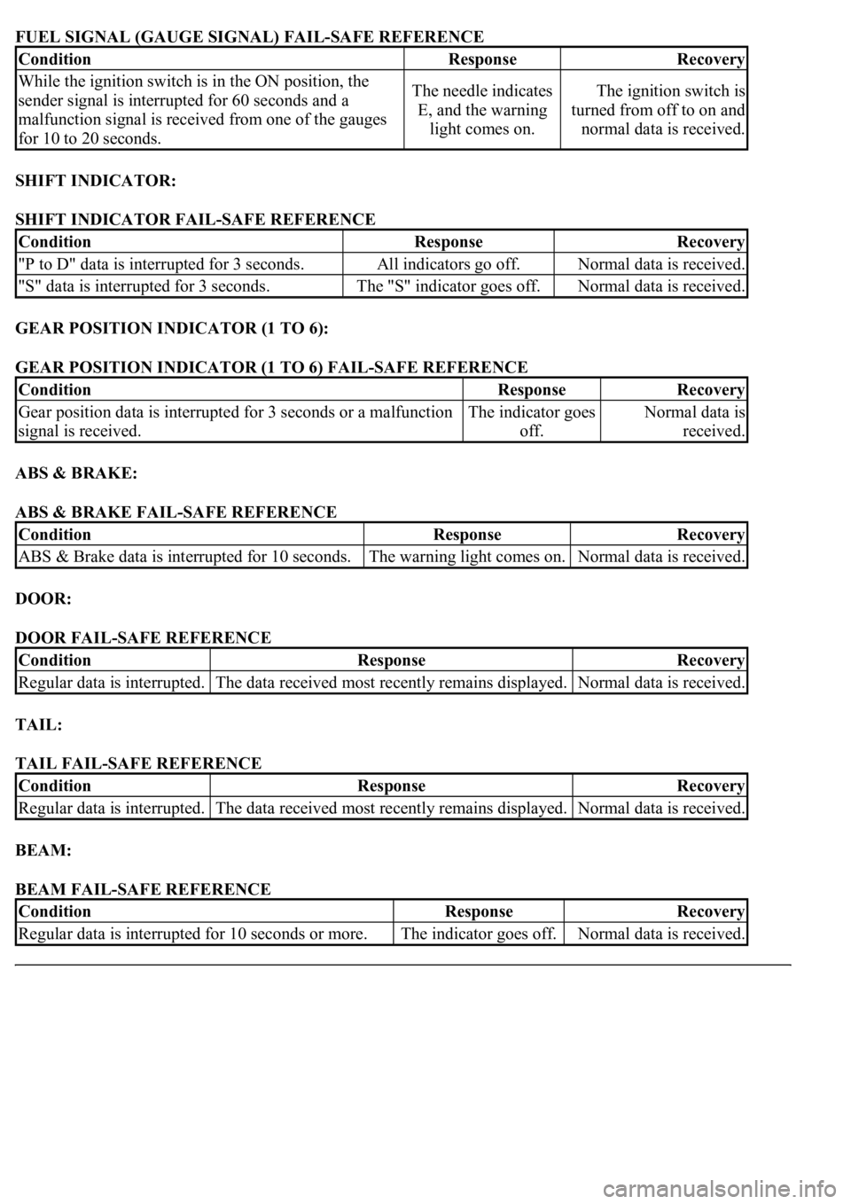
FUEL SIGNAL (GAUGE SIGNAL) FAIL-SAFE REFERENCE
SHIFT INDICATOR:
SHIFT INDICATOR FAIL-SAFE REFERENCE
GEAR POSITION INDICATOR (1 TO 6):
GEAR POSITION INDICATOR (1 TO 6) FAIL-SAFE REFERENCE
ABS & BRAKE:
ABS & BRAKE FAIL-SAFE REFERENCE
DOOR:
DOOR FAIL-SAFE REFERENCE
TAIL:
TAIL FAIL-SAFE REFERENCE
BEAM:
BEAM FAIL-SAFE REFERENCE
ConditionResponseRecovery
While the ignition switch is in the ON position, the
sender signal is interrupted for 60 seconds and a
malfunction signal is received from one of the gauges
for 10 to 20 seconds.The needle indicates
E, and the warning
light comes on.The ignition switch is
turned from off to on and
normal data is received.
ConditionResponseRecovery
"P to D" data is interrupted for 3 seconds.All indicators go off.Normal data is received.
"S" data is interrupted for 3 seconds.The "S" indicator goes off.Normal data is received.
ConditionResponseRecovery
Gear position data is interrupted for 3 seconds or a malfunction
signal is received.The indicator goes
off.Normal data is
received.
ConditionResponseRecovery
ABS & Brake data is interrupted for 10 seconds.The warning light comes on.Normal data is received.
ConditionResponseRecovery
Regular data is interrupted.The data received most recently remains displayed.Normal data is received.
ConditionResponseRecovery
Regular data is interrupted.The data received most recently remains displayed.Normal data is received.
ConditionResponseRecovery
<00350048004a0058004f00440055000300470044005700440003004c00560003004c00510057004800550055005800530057004800470003004900520055000300140013000300560048004600520051004700560003005200550003005000520055004800
11[The indicator goes off.Normal data is received.
Page 1776 of 4500
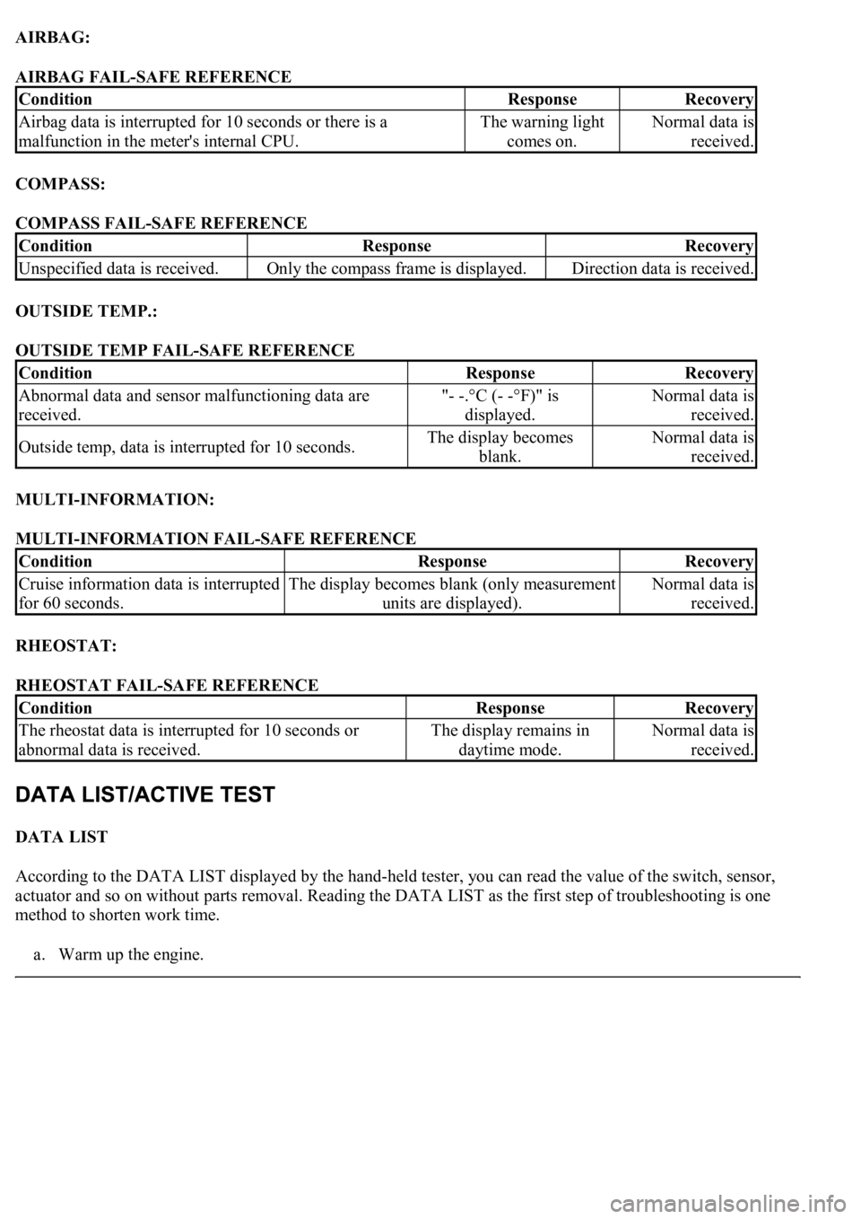
AIRBAG:
AIRBAG FAIL-SAFE REFERENCE
COMPASS:
COMPASS FAIL-SAFE REFERENCE
OUTSIDE TEMP.:
OUTSIDE TEMP FAIL-SAFE REFERENCE
MULTI-INFORMATION:
MULTI-INFORMATION FAIL-SAFE REFERENCE
RHEOSTAT:
RHEOSTAT FAIL-SAFE REFERENCE
DATA LIST
According to the DATA LIST displayed by the hand-held tester, you can read the value of the switch, sensor,
actuator and so on without parts removal. Reading the DATA LIST as the first step of troubleshooting is one
method to shorten work time.
a. Warm up the en
gine.
ConditionResponseRecovery
Airbag data is interrupted for 10 seconds or there is a
malfunction in the meter's internal CPU.The warning light
comes on.Normal data is
received.
ConditionResponseRecovery
Unspecified data is received.Only the compass frame is displayed.Direction data is received.
ConditionResponseRecovery
Abnormal data and sensor malfunctioning data are
received."- -.°C (- -°F)" is
displayed.Normal data is
received.
Outside temp, data is interrupted for 10 seconds.The display becomes
blank.Normal data is
received.
ConditionResponseRecovery
Cruise information data is interrupted
for 60 seconds.The display becomes blank (only measurement
units are displayed).Normal data is
received.
ConditionResponseRecovery
<0037004b004800030055004b004800520056005700440057000300470044005700440003004c00560003004c005100570048005500550058005300570048004700030049005200550003001400130003005600480046005200510047005600030052005500
03[
abnormal data is received.The display remains in
daytime mode.Normal data is
received.