Page 2722 of 4500
b. Fail-safe operation for mechanically malfunction:
HINT:
Fail-safe operation in the event of a mechanical system malfunction.
Fail safe function:
The ECM controls the gear position as shown in the table below when malfunctions occur.
Fig. 43: Identifying Mechanical Malfunction Chart
Courtesy of TOYOTA MOTOR SALES, U.S.A., INC.
DATA LIST/ACTIVE TEST
1.DATA LIST
HINT:
According to the DATA LIST displayed by the hand-held tester, you can read the value of the switch,
sensor, actuator and so on without parts removal. Reading the DATA LIST as the first step of
troubleshooting is one method to shorten labor time.
Page 2726 of 4500

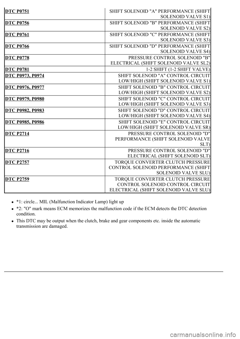
*1: circle... MIL (Malfunction Indicator Lamp) light up
*2: "O" mark means ECM memorizes the malfunction code if the ECM detects the DTC detection
condition.
This DTC may be output when the clutch, brake and gear components etc. inside the automatic
transmission are dama
ged.
DTC P0751SHIFT SOLENOID "A" PERFORMANCE (SHIFT
SOLENOID VALVE S1)
DTC P0756SHIFT SOLENOID "B" PERFORMANCE (SHIFT
SOLENOID VALVE S2)
DTC P0761SHIFT SOLENOID "C" PERFORMANCE (SHIFT
SOLENOID VALVE S3)
DTC P0766SHIFT SOLENOID "D" PERFORMANCE (SHIFT
SOLENOID VALVE S4)
DTC P0778PRESSURE CONTROL SOLENOID "B"
ELECTRICAL (SHIFT SOLENOID VALVE SL2)
DTC P07811-2 SHIFT (1-2 SHIFT VALVE)
DTC P0973, P0974SHIFT SOLENOID "A" CONTROL CIRCUIT
LOW/HIGH (SHIFT SOLENOID VALVE S1)
DTC P0976, P0977SHIFT SOLENOID "B" CONTROL CIRCUIT
LOW/HIGH (SHIFT SOLENOID VALVE S2)
DTC P0979, P0980SHIFT SOLENOID "C" CONTROL CIRCUIT
LOW/HIGH (SHIFT SOLENOID VALVE S3)
DTC P0982, P0983SHIFT SOLENOID "D" CONTROL CIRCUIT
LOW/HIGH (SHIFT SOLENOID VALVE S4)
DTC P0985, P0986SHIFT SOLENOID "E" CONTROL CIRCUIT
LOW/HIGH (SHIFT SOLENOID VALVE SR)
DTC P2714PRESSURE CONTROL SOLENOID "D"
PERFORMANCE (SHIFT SOLENOID VALVE
SLT)
DTC P2716PRESSURE CONTROL SOLENOID "D"
ELECTRICAL (SHIFT SOLENOID SLT)
DTC P2757TORQUE CONVERTER CLUTCH PRESSURE
CONTROL SOLENOID PERFORMANCE (SHIFT
SOLENOID VALVE SLU)
DTC P2759TORQUE CONVERTER CLUTCH PRESSURE
CONTROL SOLENOID CONTROL CIRCUIT
ELECTRICAL (SHIFT SOLENOID VALVE SLU)
Page 2729 of 4500
CIRCUIT DESCRIPTION
The park/neutral position switch detects the shift lever position and sends signals to the ECM.
Fig. 49: DTC Reference Chart
Courtesy of TOYOTA MOTOR SALES, U.S.A., INC.
MONITOR DESCRIPTION
These DTCs indicate a problem with the park/neutral position switch and the wire harness in the park/neutral
position switch circuit.
The park/neutral position switch detects the shift lever position and sends signals to the ECM.
For security, the park/neutral position switch detects the shift lever position so that engine can be started only
when the vehicle is in P or N shift position.
When the park/neutral position switch sends more than one signal at a time from switch positions P, R, N or D,
the ECM interprets this as a fault in the switch. The ECM will turn on the MIL and store the DTC.
MONITOR STRATEGY
P0705:
MONITOR STRATEGY TABLE - P0705
Related DTCsP0705: Park/neutral position switch/Verify switch
input
Page 2731 of 4500
One of the following conditions is met: Condition (A), (B) and (C) Condition (A)
TYPICAL MALFUNCTION THRESHOLDS TABLE - P0705
Condition (B)
When shift lever is in S position, one of the following conditions is met
TYPICAL MALFUNCTION THRESHOLDS TABLE - CONDITION B
Condition (C)
All of following conditions are met
TYPICAL MALFUNCTION THRESHOLDS TABLE - CONDITION C
P0850:
TYPICAL MALFUNCTION THRESHOLDS TABLE - P0850
COMPONENT OPERATING RANGE
P0705:
COMPONENT OPERATING RANGE TABLE - P0705
P0850:
Number of the following signal input at the same
time
2 or more
P switchON
N switchON
R switchON
D switchON
P switchON
N switchON
R switchON
P switchOFF
N switchOFF
R switchOFF
D switchOFF
NSW switchON
Park/neutral position switchThe park/neutral position switch sends only one
signal to the ECM.
Page 2738 of 4500
Fig. 55: Transmission Control Switch Reference Chart
Courtesy of TOYOTA MOTOR SALES, U.S.A., INC.
NG: REPLACE TRANSMISSION CONTROL SWITCH (See COMPONENTS
)
OK: Go to next step
3.CHECK HARNESS AND CONNECTOR (PARK/NEUTRAL POSITION SWITCH -ECM)
a. Connect the transmission control switch connector of shift lock control unit assy.
b. Turn the ignition switch to the ON position, and measure the voltage according to the value(s) in
the table below when the shift lever is moved to each position.
Page 2739 of 4500
Fig. 56: Identifying ECM Connector Terminals
Courtesy of TOYOTA MOTOR SALES, U.S.A., INC.
Standard:
Page 2740 of 4500
Fig. 57: ECM Connector Terminals Reference Chart
Courtesy of TOYOTA MOTOR SALES, U.S.A., INC.
NG: REPAIR OR REPLACE HARNESS OR CONNECTOR (SeeELECTRONIC CIRCUIT
INSPECTION PROCEDURE )
OK: REPLACE ECM (See REPLACEMENT
)
DTC P0710, P0712, P0713: TRANSMISSION FLUID TEMPERATURE SENSOR "A" CIRCUIT
LOW/HIGH INPUT
CIRCUIT DESCRIPTION
The ATF (Automatic Transmission Fluid) temperature sensor converts the fluid temperature into a resistance
value which is input into the ECM.
The ECM applies a voltage to the temperature sensor through ECM terminal OIL.
The sensor resistance changes with the transmission fluid temperature. As the temperature becomes higher, the
sensor resistance decreases.
One terminal of the sensor is grounded so that the sensor resistance decreases and the voltage goes down as the
temperature becomes higher.
The ECM calculates the fluid temperature based on the volta
ge signal.
Page 2742 of 4500

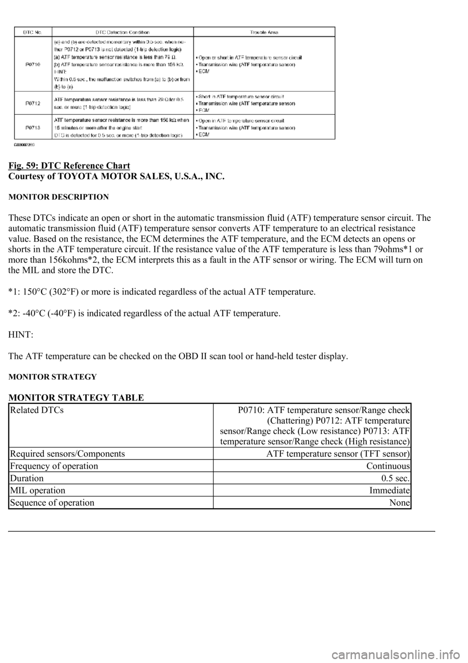
Fig. 59: DTC Reference Chart
Courtesy of TOYOTA MOTOR SALES, U.S.A., INC.
MONITOR DESCRIPTION
These DTCs indicate an open or short in the automatic transmission fluid (ATF) temperature sensor circuit. The
automatic transmission fluid (ATF) temperature sensor converts ATF temperature to an electrical resistance
value. Based on the resistance, the ECM determines the ATF temperature, and the ECM detects an opens or
shorts in the ATF temperature circuit. If the resistance value of the ATF temperature is less than 79ohms*1 or
more than 156kohms*2, the ECM interprets this as a fault in the ATF sensor or wiring. The ECM will turn on
the MIL and store the DTC.
*1: 150°C (302°F) or more is indicated regardless of the actual ATF temperature.
*2: -40°C (-40°F) is indicated regardless of the actual ATF temperature.
HINT:
The ATF temperature can be checked on the OBD II scan tool or hand-held tester display.
MONITOR STRATEGY
MONITOR STRATEGY TABLE
Related DTCsP0710: ATF temperature sensor/Range check
(Chattering) P0712: ATF temperature
sensor/Range check (Low resistance) P0713: ATF
temperature sensor/Range check (High resistance)
Required sensors/ComponentsATF temperature sensor (TFT sensor)
Frequency of operationContinuous
Duration0.5 sec.
MIL operationImmediate
Sequence of operationNone