Page 2032 of 4500
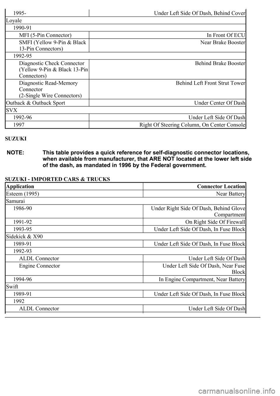
SUZUKI
SUZUKI - IMPORTED CARS & TRUCKS
1995-Under Left Side Of Dash, Behind Cover
Loyale
1990-91
MFI (5-Pin Connector)In Front Of ECU
SMFI (Yellow 9-Pin & Black
13-Pin Connectors)Near Brake Booster
1992-95
Diagnostic Check Connector
(Yellow 9-Pin & Black 13-Pin
Connectors)Behind Brake Booster
Diagnostic Read-Memory
Connector
(2-Single Wire Connectors)Behind Left Front Strut Tower
Outback & Outback SportUnder Center Of Dash
SVX
1992-96Under Left Side Of Dash
1997Right Of Steering Column, On Center Console
ApplicationConnector Location
Esteem (1995)Near Battery
Samurai
1986-90Under Right Side Of Dash, Behind Glove
Compartment
1991-92On Right Side Of Firewall
1993-95Under Left Side Of Dash, In Fuse Block
Sidekick & X90
1989-91Under Left Side Of Dash, In Fuse Block
1992-93
ALDL ConnectorUnder Left Side Of Dash
Engine ConnectorUnder Left Side Of Dash, Near Fuse
Block
1994-96In Engine Compartment, Near Battery
Swift
1989-91Under Left Side Of Dash, In Fuse Block
1992
ALDL ConnectorUnder Left Side Of Dash
Page 2033 of 4500
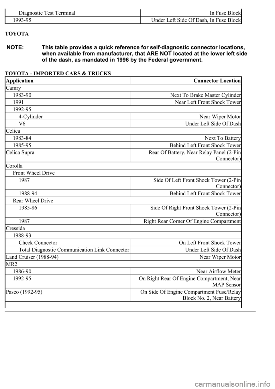
TOYOTA
TOYOTA - IMPORTED CARS & TRUCKS
Diagnostic Test TerminalIn Fuse Block
1993-95Under Left Side Of Dash, In Fuse Block
ApplicationConnector Location
Camry
1983-90Next To Brake Master Cylinder
1991Near Left Front Shock Tower
1992-95
4-CylinderNear Wiper Motor
V6Under Left Side Of Dash
Celica
1983-84Next To Battery
1985-95Behind Left Front Shock Tower
Celica SupraRear Of Battery, Near Relay Panel (2-Pin
Connector)
Corolla
Front Wheel Drive
1987Side Of Left Front Shock Tower (2-Pin
Connector)
1988-94Behind Left Front Shock Tower
Rear Wheel Drive
1985-86Side Of Right Front Shock Tower (2-Pin
Connector)
1987Right Rear Corner Of Engine Compartment
Cressida
1988-93
Check ConnectorOn Left Front Shock Tower
Total Diagnostic Communication Link ConnectorUnder Left Side Of Dash
Land Cruiser (1988-94)Near Wiper Motor
MR2
1986-90Near Airflow Meter
1992-95On Right Rear Of Engine Compartment, Near
MAP Sensor
Paseo (1992-95)On Side Of Engine Compartment Fuse/Relay
Block No. 2, Near Battery
Page 2034 of 4500
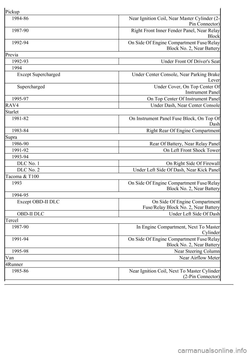
Pickup
1984-86Near Ignition Coil, Near Master Cylinder (2-
Pin Connector)
1987-90Right Front Inner Fender Panel, Near Relay
Block
1992-94On Side Of Engine Compartment Fuse/Relay
Block No. 2, Near Battery
Previa
1992-93Under Front Of Driver's Seat
1994
Except SuperchargedUnder Center Console, Near Parking Brake
Lever
SuperchargedUnder Cover, On Top Center Of
Instrument Panel
1995-97On Top Center Of Instrument Panel
RAV4Under Dash, Near Center Console
Starlet
1981-82On Instrument Panel Fuse Block, On Top Of
Dash
1983-84Right Rear Of Engine Compartment
Supra
1986-90Rear Of Battery, Near Relay Panel
1991-92On Left Front Shock Tower
1993-94
DLC No. 1On Right Side Of Firewall
DLC No. 2Under Left Side Of Dash, Near Kick Panel
Tacoma & T100
1993On Side Of Engine Compartment Fuse/Relay
Block No. 2, Near Battery
1994-95
Except OBD-II DLCOn Side Of Engine Compartment
Fuse/Relay Block No. 2, Near Battery
OBD-II DLCUnder Left Side Of Dash
Tercel
1987-90In Engine Compartment, Next To Master
Cylinder
1991-94On Side Of Engine Compartment Fuse/Relay
Block No. 2, Near Battery
1995-98Near Steering Column
VanNear Airflow Meter
4Runner
1985-86Near Ignition Coil, Next To Master Cylinder
(2-Pin Connector)
Page 2035 of 4500
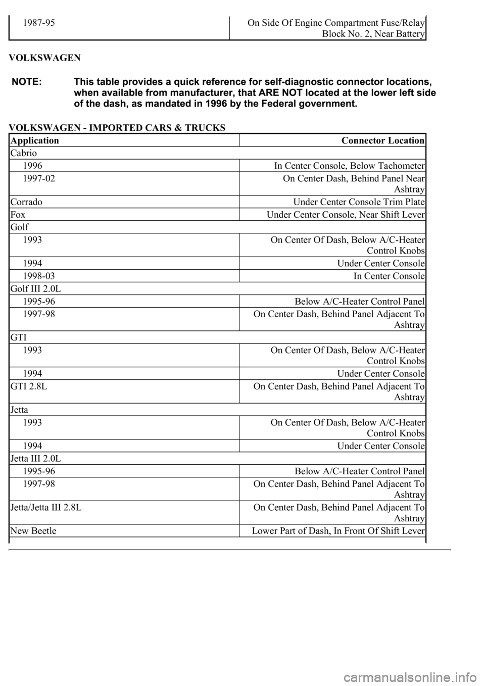
VOLKSWAGEN
VOLKSWAGEN - IMPORTED CARS & TRUCKS
1987-95On Side Of Engine Compartment Fuse/Relay
Block No. 2, Near Battery
ApplicationConnector Location
Cabrio
1996In Center Console, Below Tachometer
1997-02On Center Dash, Behind Panel Near
Ashtray
CorradoUnder Center Console Trim Plate
FoxUnder Center Console, Near Shift Lever
Golf
1993On Center Of Dash, Below A/C-Heater
Control Knobs
1994Under Center Console
1998-03In Center Console
Golf III 2.0L
1995-96Below A/C-Heater Control Panel
1997-98On Center Dash, Behind Panel Adjacent To
Ashtray
GTI
1993On Center Of Dash, Below A/C-Heater
Control Knobs
1994Under Center Console
GTI 2.8LOn Center Dash, Behind Panel Adjacent To
Ashtray
Jetta
1993On Center Of Dash, Below A/C-Heater
Control Knobs
1994Under Center Console
Jetta III 2.0L
1995-96Below A/C-Heater Control Panel
1997-98On Center Dash, Behind Panel Adjacent To
Ashtray
Jetta/Jetta III 2.8LOn Center Dash, Behind Panel Adjacent To
Ashtray
New BeetleLower Part of Dash, In Front Of Shift Lever
Page 2046 of 4500
OVERHAUL
HINT:
See COMPONENTS
1.REMOVE REAR WHEEL
2.REMOVE EXHAUST PIPE ASSY (SEE REPLACEMENT
)
3.REMOVE FRONT FLOOR HEAT INSULATOR NO.1 (SEE OVERHAUL
)
4.REMOVE PROPELLER SHAFT HEAT INSULATOR (SEE OVERHAUL
)
5.REMOVE PROPELLER W/CENTER BEARING SHAFT ASSY (SEE OVERHAUL
)
6.REMOVE REAR DIFFERENTIAL FILLER PLUG
a. Using a hexagon wrench (10 mm), remove the filler plug and gasket.
7.REMOVE REAR DIFFERENTIAL DRAIN PLUG
a. Using a hexagon wrench (10 mm), remove the drain plug and gasket.
b. Drain the differential oil.
8.REMOVE REAR DRIVE SHAFT ASSY LH (SEE REPLACEMENT
)
9.REMOVE REAR DRIVE SHAFT ASSY RH
HINT:
Removal procedure of the RH side is the same as that of the LH side.
10.REMOVE STABILIZER BAR REAR (SEE REPLACEMENT
)
HINT:
Perform this procedure only when the rear differential mount cushion should be changed.
11.REMOVE HEIGHT CONTROL VALVE SUB-ASSY NO.2 (W/ AIR SUSPENSION) (SEE
REPLACEMENT
)
HINT:
Perform this procedure only when the rear differential mount cushion should be changed.
12.REMOVE DIFFERENTIAL CARRIER ASSY REAR
a. Support the differential carrier with a jack and wooden block.
Page 2098 of 4500
Fig. 58: Aligning Matchmarks On Ring Gear And Differential Case
Courtesy of TOYOTA MOTOR SALES, U.S.A., INC.
47.INSTALL REAR DIFFERENTIAL CASE BOLT
a. Clean the differential ring gear set bolt hole.
b. After the ring gear has been cooled sufficiently, install the new 8 ring gear set bolts to which thread
lock has been applied.
Thread lock:
Part No. 08833-00100, THREE BOND 1360 K or equivalent.
Page 2107 of 4500
Fig. 67: Adjusting Drive Pinion Preload
Courtesy of TOYOTA MOTOR SALES, U.S.A., INC.
c. Using SST and a torque wrench, measure the preload.
Drive pinion preload (at starting):
New bearing:
1.5 to 2.0 N.m (15 to 21 kgf.cm, 13 to 18 in..lbf)
Reused bearing:
0.5 to 0.8 N.m (5 to 8 kgf.cm, 4.3 to 6.9 in..lbf)
HINT:
Do not apply hypoid gear oil if a new bearing is used.
Turn the bearing clockwise and counterclockwise several times to stabilize the bearing,
and then measure the backlash.
If the preload is not within the specification, adjust the rear differential drive pinion
preload or repair as necessar
y.
Page 2113 of 4500
Fig. 73: Installing Rear Differential Side Gear Shaft Snap Ring
Courtesy of TOYOTA MOTOR SALES, U.S.A., INC.
b. Install a dial indicator to the differential carrier.
c. Tighten the SST bolt to alter the differential carrier's shape by approximately 0.1 mm
(0.004 in.).
SST 09571-50010
HINT:
Set the dial indicator to the rearmost position (upper side in the illustration) of
the area around where the side gear shaft oil seal is tapped in.
Tighten the SST bolt to apply the preload to the case bearing.
d. Turn the rin
g gear clockwise and counterclockwise several times.