Page 2225 of 4500
NG: REPAIR OR REPLACE HARNESS AND CONNECTOR
OK: PROCEED TO NEXT CIRCUIT INSPECTION SHOWN ON PROBLEM SYMPTOMS
TABLE
CIRCUIT DESCRIPTION
The door lock assembly has a built-in closer position switch, which detects the position of the closer.
WIRING DIAGRAM
Fig. 54: Door Closer Position Switch Circuit On Driver Side Door
- Wiring Diagram
Courtesy of TOYOTA MOTOR SALES, U.S.A., INC.
INSPECTION PROCEDURE
1.READ VALUE OF DATA LIST (DOOR CLOSER POSITION SWITCH (POLE/HALF/ FULL))
a. Check the DATA LIST for proper functioning of the door closer position switch.
DRIVER DOOR EC
R14-1 (CPUB) - Body groundAlways10 to 14 V
R14-2 (BDR) - Body groundAlways10 to 14 V
R14-26 (SIG) Body groundIgnition switch ON10 to 14 V
Measurement item / Display
Page 2226 of 4500
OK: "ON" (door closer position switch (POLE/HALF/FULL) is ON) appears on the screen.
NG: Go to step 2
OK: PROCEED TO NEXT CIRCUIT INSPECTION SHOWN ON PROBLEM SYMPTOMS
TABLE
2.INSPECT COMBINATION SWITCH ASSY (HALF LATCH AND FULL LATCH SWITCH)
a. Disconnect the F23-a lock connector.
b. Measure the resistance.
Item(Range)Normal ConditionPosition
POLE SWPawl switch signal/ ON or OFFRefer to system description of door ECU
(SEE SYSTEM DESCRIPTION
)
-
HALF SWHalf switch signal/ ON or OFFRefer to system description of door ECU
(SEE SYSTEM DESCRIPTION
)
-
FULL SWFull switch signal/ ON or OFFRefer to system description of door ECU
(SEE SYSTEM DESCRIPTION
)
-
Page 2228 of 4500
TERMINALS RESISTANCE REFERENCE
NG: REPLACE COMBINATION SWITCH ASSY
OK: Go to Next Step.
3.INSPECT COMBINATION SWITCH ASSY (PAWL SWITCH)
a. Disconnect the F23-a lock connector.
b. Measure the resistance.
TERMINALS RESISTANCE REFERENCE
Tester ConnectionConditionSpecified Condition
1 - 5Door openBelow 1 ohms
1 - 5Half latch10 kohms or higher
1 - 5Door close10 kohms or higher
4 - 5Door openBelow 1 ohms
4 - 5Half latchBelow 1 ohms
4 - 5Door closed10 ohms or higher
Tester ConnectionConditionSpecified Condition
2 - 5Link not pushed10 kohms or higher
2 - 5Link pushedBelow 1 ohms
Page 2230 of 4500
OK: Go to Next Step.
4.CHECK WIRE HARNESS (DRIVER DOOR ECU - FRONT DOOR LOCK ASSY LH)
a. Disconnect the F23-a lock connector.
b. Disconnect the F23 ECU connector.
c. Measure the resistance of the wire harness side connectors.
Page 2232 of 4500
Fig. 57: Checking Wire Harness (Driver Door ECU -Front Door Lock Assy LH)
Courtesy of TOYOTA MOTOR SALES, U.S.A., INC.
TERMINALS RESISTANCE REFERENCE
NG: REPLACE COMBINATION SWITCH ASSY
OK: PROCEED TO NEXT CIRCUIT INSPECTION SHOWN ON PROBLEM SYMPTOMS
TABLE
CIRCUIT DESCRIPTION
The door lock assembly has a built-in closer position switch, which detects the position of the closer.
WIRING DIAGRAM
Tester ConnectionSpecified Condition
F23-a-2 - F23-23 (POLE)Below 1 ohms
F23-a-1 - F23-24 (HALF)Below 1 ohms
F23-a-4 - F23-15 (FULL)Below 1 ohms
F23-a-5 - F23-21 (KEYE)Below 1 ohms
F23-a-2 - Body ground10 kohms or higher
F23-a-1 - Body ground10 kohms or higher
F23-a-4 - Body ground10 kohms or higher
F23-a-5 - Body ground10 kohms or higher
Page 2233 of 4500

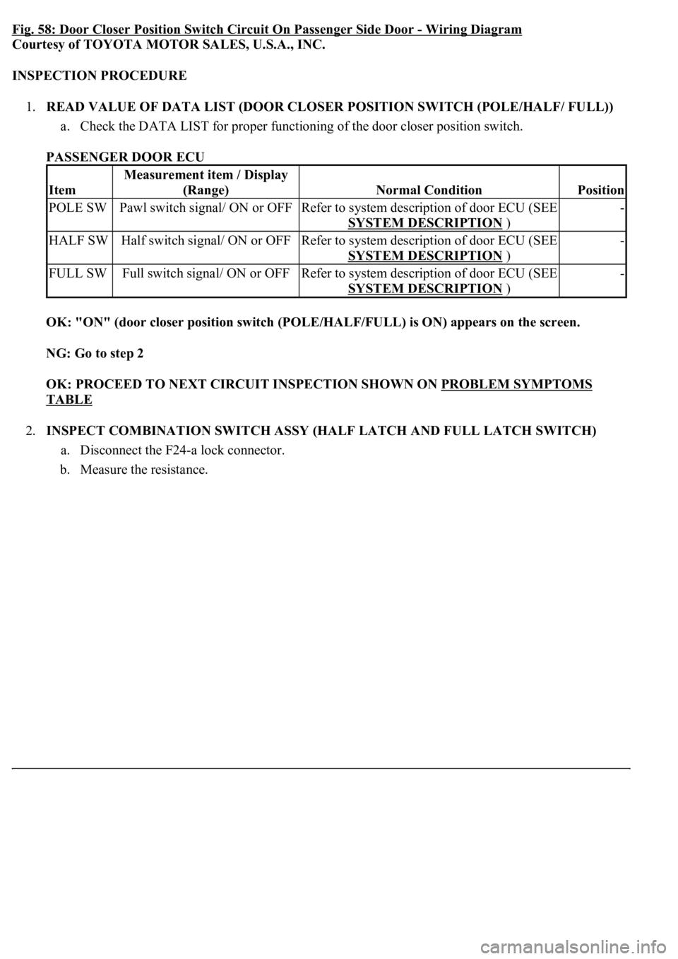
Fig. 58: Door Closer Position Switch Circuit On Passenger Side Door -Wiring Diagram
Courtesy of TOYOTA MOTOR SALES, U.S.A., INC.
INSPECTION PROCEDURE
1.READ VALUE OF DATA LIST (DOOR CLOSER POSITION SWITCH (POLE/HALF/ FULL))
a. Check the DATA LIST for proper functioning of the door closer position switch.
PASSENGER DOOR ECU
OK: "ON" (door closer position switch (POLE/HALF/FULL) is ON) appears on the screen.
NG: Go to step 2
OK: PROCEED TO NEXT CIRCUIT INSPECTION SHOWN ON PROBLEM SYMPTOMS
TABLE
2.INSPECT COMBINATION SWITCH ASSY (HALF LATCH AND FULL LATCH SWITCH)
a. Disconnect the F24-a lock connector.
b. Measure the resistance.
Item
Measurement item / Display
(Range)
Normal ConditionPosition
POLE SWPawl switch signal/ ON or OFFRefer to system description of door ECU (SEE
SYSTEM DESCRIPTION
)
-
HALF SWHalf switch signal/ ON or OFFRefer to system description of door ECU (SEE
SYSTEM DESCRIPTION
)
-
FULL SWFull switch signal/ ON or OFFRefer to system description of door ECU (SEE
SYSTEM DESCRIPTION
)
-
Page 2235 of 4500
TERMINALS RESISTANCE REFERENCE
NG: REPLACE COMBINATION SWITCH ASSY
OK: Go to Next Step.
3.INSPECT COMBINATION SWITCH ASSY (PAWL SWITCH)
a. Disconnect the F24-a lock connector.
b. Measure the resistance.
TERMINALS RESISTANCE REFERENCE
Tester ConnectionConditionSpecified Condition
1 - 5Door openBelow 1 ohms
1 - 5Half latch10 kohms or higher
1 - 5Door close10 kohms or higher
4 - 5Door openBelow 1 ohms
4 - 5Half latchBelow 1 ohms
4 - 5Door closed10 kohms or higher
Tester ConnectionConditionSpecified Condition
2 - 5Link not pushed10 kohms or higher
2 - 5Link pushedBelow 1 ohms
Page 2237 of 4500
Fig. 60: Inspecting Combination Switch Assy (Pawl Switch)
Courtesy of TOYOTA MOTOR SALES, U.S.A., INC.
NG: REPLACE COMBINATION SWITCH ASSY
OK: Go to Next Step.
4.CHECK WIRE HARNESS (PASSENGER DOOR ECU - FRONT DOOR LOCK ASSY RH)
a. Disconnect the F24-a lock connector.
b. Disconnect the F24 ECU connector.
c. Measure the resistance of the wire harness side connectors.
TERMINALS RESISTANCE REFERENCE
Tester ConnectionSpecified Condition
F24-a-2 - F24-23 (POLE)Below 1 ohms
F24-a-1 - F24-24 (HALF)Below 1 ohms
F24-a-4 - F24-15 (FULL)Below 1 ohms
F24-a-5 - F24-21 (KEYE)Below 1 ohms
F24-a-2 - Body ground10 kohms or higher
F24-a-1 - Body ground10 kohms or higher
F24-a-4 - Body ground10 kohms or higher
F24-a-5 - Body ground10 kohms or higher