Page 1191 of 4500
1.STEERING SYSTEM HANDLING PRECAUTIONS
a. Care must be taken when replacing parts. Incorrect replacement could affect the performance of the
steering system and result in hazardous driving.
2.SRS AIRBAG SYSTEM HANDLING PRECAUTIONS
a. The LEXUS LS430 is equipped with an SRS (Supplemental Restraint System) such as the driver's
airbag and front passenger airbag. Failure to carry out service operations in correct sequence could
cause unexpected SRS deployment during servicing and may lead to a serious accident. Before
servicing (including removal or installation of parts, inspection or replacement), be sure to read the
precautionary notice for the supplemental restraint system (see PRECAUTION
).
Fig. 1: [Identifying Bus Line]
Courtesy of TOYOTA MOTOR SALES, U.S.A., INC.
3.BUS LINE REPAIR
a. After repairing the bus line with solder, wrap the repaired part with vinyl tape (see ELECTRONIC
CIRCUIT INSPECTION PROCEDURE ).
Page 1523 of 4500
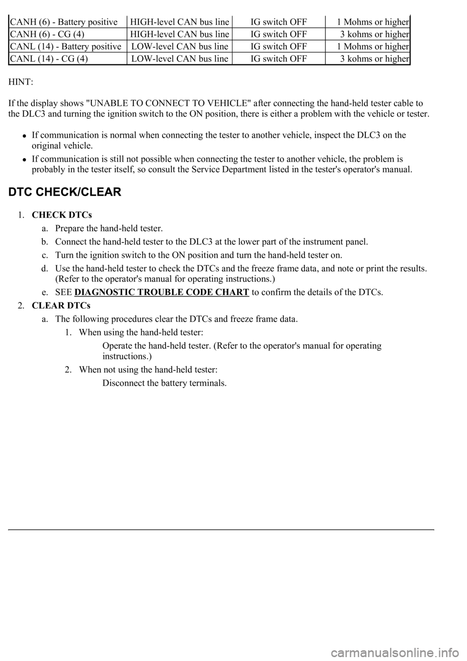
HINT:
If the display shows "UNABLE TO CONNECT TO VEHICLE" after connecting the hand-held tester cable to
the DLC3 and turning the ignition switch to the ON position, there is either a problem with the vehicle or tester.
If communication is normal when connecting the tester to another vehicle, inspect the DLC3 on the
original vehicle.
If communication is still not possible when connecting the tester to another vehicle, the problem is
probably in the tester itself, so consult the Service Department listed in the tester's operator's manual.
1.CHECK DTCs
a. Prepare the hand-held tester.
b. Connect the hand-held tester to the DLC3 at the lower part of the instrument panel.
c. Turn the ignition switch to the ON position and turn the hand-held tester on.
d. Use the hand-held tester to check the DTCs and the freeze frame data, and note or print the results.
(Refer to the operator's manual for operating instructions.)
e. SEE DIAGNOSTIC TROUBLE CODE CHART
to confirm the details of the DTCs.
2.CLEAR DTCs
a. The following procedures clear the DTCs and freeze frame data.
1. When using the hand-held tester:
Operate the hand-held tester. (Refer to the operator's manual for operating
instructions.)
2. When not using the hand-held tester:
Disconnect the battery terminals.
CANH (6) - Battery positiveHIGH-level CAN bus lineIG switch OFF1 Mohms or higher
CANH (6) - CG (4)HIGH-level CAN bus lineIG switch OFF3 kohms or higher
CANL (14) - Battery positiveLOW-level CAN bus lineIG switch OFF1 Mohms or higher
CANL (14) - CG (4)LOW-level CAN bus lineIG switch OFF3 kohms or higher
Page 1605 of 4500
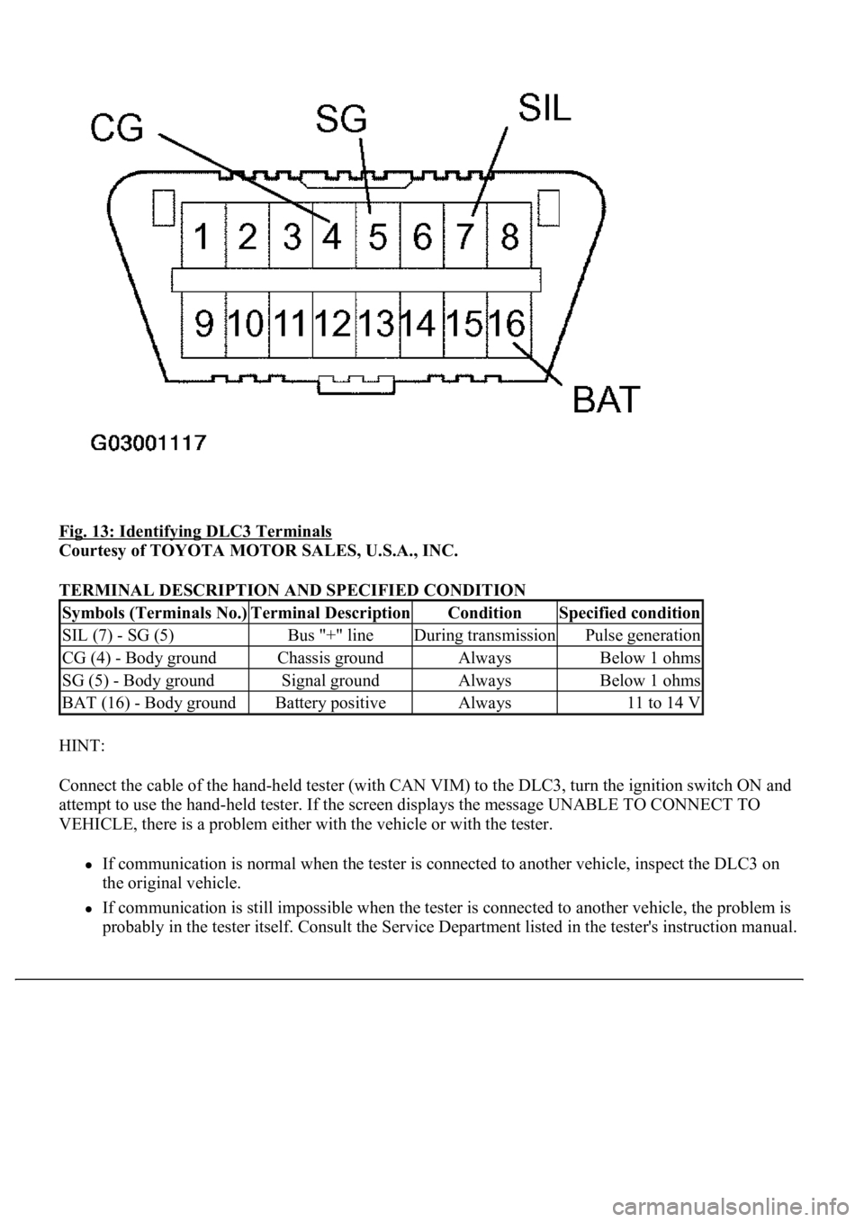
Fig. 13: Identifying DLC3 Terminals
Courtesy of TOYOTA MOTOR SALES, U.S.A., INC.
TERMINAL DESCRIPTION AND SPECIFIED CONDITION
HINT:
Connect the cable of the hand-held tester (with CAN VIM) to the DLC3, turn the ignition switch ON and
attempt to use the hand-held tester. If the screen displays the message UNABLE TO CONNECT TO
VEHICLE, there is a problem either with the vehicle or with the tester.
If communication is normal when the tester is connected to another vehicle, inspect the DLC3 on
the original vehicle.
If communication is still impossible when the tester is connected to another vehicle, the problem is
probably in the tester itself. Consult the Service Department listed in the tester's instruction manual.
Symbols (Terminals No.)Terminal DescriptionConditionSpecified condition
SIL (7) - SG (5)Bus "+" lineDuring transmissionPulse generation
CG (4) - Body groundChassis groundAlwaysBelow 1 ohms
SG (5) - Body groundSignal groundAlwaysBelow 1 ohms
BAT (16) - Body groundBattery positiveAlways11 to 14 V
Page 1769 of 4500
If the communication is normal when the tool is connected to another vehicle, inspect the DLC3 on
the original vehicle.
If the communication is still impossible when the tool is connected to another vehicle, the problem
is probably in the tool itself, so consult the Service Department listed in the tool's instruction
manual.
2.DIAGNOSIS CHECK (MULTI- INFORMATION DISPLAY)
a. Switch to diagnosis mode
1. Connect terminal 13 (TC) and 4 (CG) of the DLC3 using SST.
Fig. 32: Identifying Terminal 13 (TC) And 4 (CG) Of DLC3
Courtesy of TOYOTA MOTOR SALES, U.S.A., INC.
2. The display in the warning area shows "DIAG" when the ignition switch is turned to the ON
position.
3. Each system can be switched by pushing the "DISP1" switch on the steering pad switch.
HINT:
Dia
gnosis checks for the EFI, VSC and CRUISE systems can be done by using the displayed items
Page 1917 of 4500
hand-held tester to the DLC3, turned the ignition switch to the ON position and operated the tester,
there is a problem on either the vehicle side or the tool side.
If communication is normal when the tool is connected to another vehicle, inspect the DLC3
on the original vehicle.
If communication is still impossible when the tool is connected to another vehicle, the
problem is probably in the tool itself, so consult the Service Department listed in the tool's
instruction manual.
3.CHECK THE INDICATOR
a. Turn the ignition switch to the ON position.
b. Check that the CRUISE main indicator light comes on when the cruise control main switch ON-
OFF button is push on, and that the indicator light goes off when the ON-OFF button is pushed off.
Fig. 13: Identifying CRUISE Main Indicator Light
Courtesy of TOYOTA MOTOR SALES, U.S.A., INC.
HINT:
If there is a problem with the indicator, inspect the CRUISE MAIN INDICATOR LIGHT CIRCUIT
.
HINT:
Page 1996 of 4500
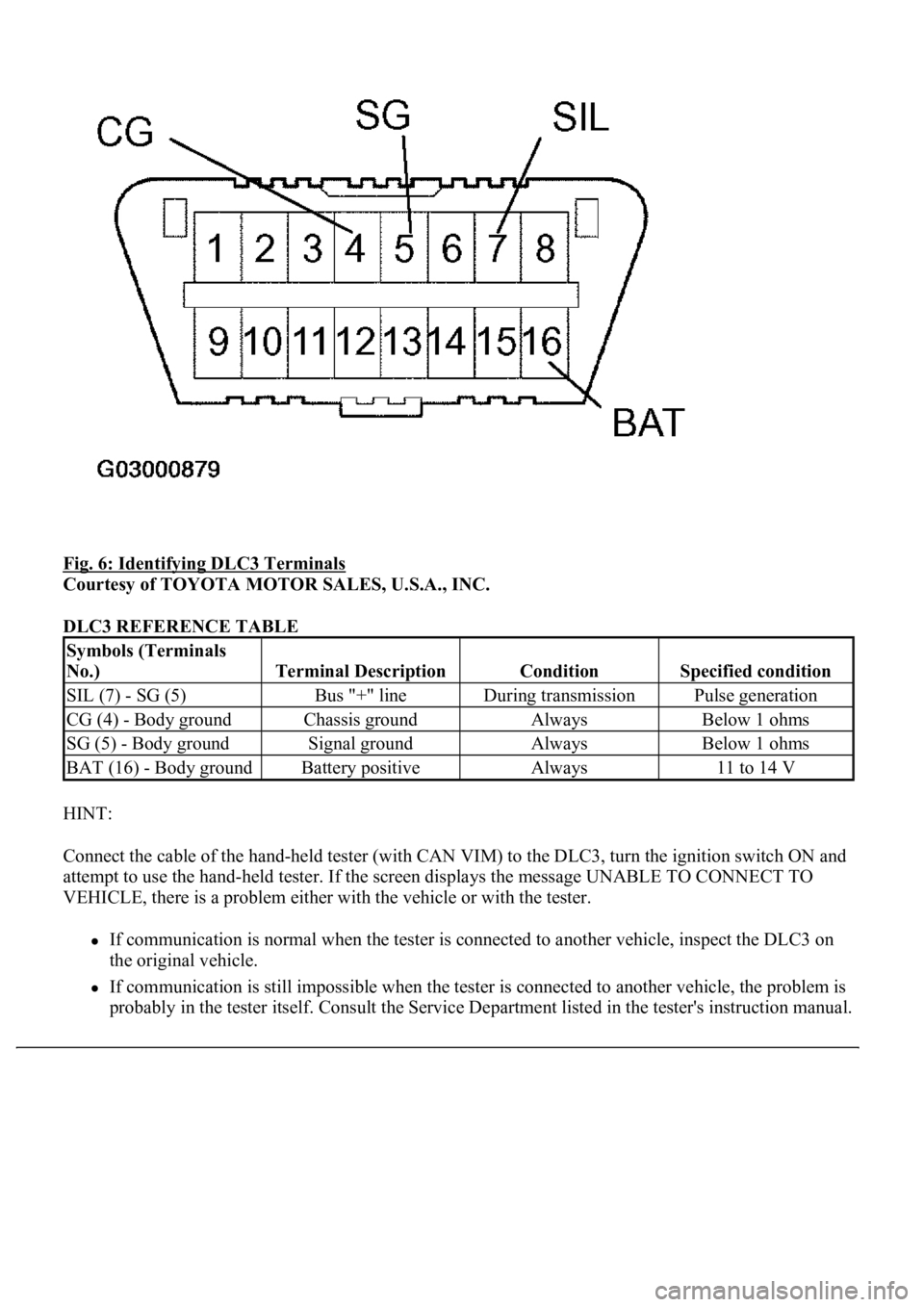
Fig. 6: Identifying DLC3 Terminals
Courtesy of TOYOTA MOTOR SALES, U.S.A., INC.
DLC3 REFERENCE TABLE
HINT:
Connect the cable of the hand-held tester (with CAN VIM) to the DLC3, turn the ignition switch ON and
attempt to use the hand-held tester. If the screen displays the message UNABLE TO CONNECT TO
VEHICLE, there is a problem either with the vehicle or with the tester.
If communication is normal when the tester is connected to another vehicle, inspect the DLC3 on
the original vehicle.
If communication is still impossible when the tester is connected to another vehicle, the problem is
probabl
y in the tester itself. Consult the Service Department listed in the tester's instruction manual.
Symbols (Terminals
No.)
Terminal DescriptionConditionSpecified condition
SIL (7) - SG (5)Bus "+" lineDuring transmissionPulse generation
CG (4) - Body groundChassis groundAlwaysBelow 1 ohms
SG (5) - Body groundSignal groundAlwaysBelow 1 ohms
BAT (16) - Body groundBattery positiveAlways11 to 14 V
Page 2196 of 4500
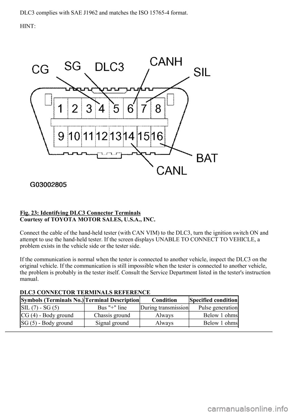
DLC3 complies with SAE J1962 and matches the ISO 15765-4 format.
HINT:
Fig. 23: Identifying DLC3 Connector Terminals
Courtesy of TOYOTA MOTOR SALES, U.S.A., INC.
Connect the cable of the hand-held tester (with CAN VIM) to the DLC3, turn the ignition switch ON and
attempt to use the hand-held tester. If the screen displays UNABLE TO CONNECT TO VEHICLE, a
problem exists in the vehicle side or the tester side.
If the communication is normal when the tester is connected to another vehicle, inspect the DLC3 on the
original vehicle. If the communication is still impossible when the tester is connected to another vehicle,
the problem is probably in the tester itself. Consult the Service Department listed in the tester's instruction
manual.
DLC3 CONNECTOR TERMINALS REFERENCE
Symbols (Terminals No.)Terminal DescriptionConditionSpecified condition
SIL (7) - SG (5)Bus "+" lineDuring transmissionPulse generation
CG (4) - Body groundChassis groundAlwaysBelow 1 ohms
SG (5) - Body groundSignal groundAlwaysBelow 1 ohms
Page 2462 of 4500
tester to the DLC3, turned the ignition switch to the ON position and operated the tester, there is a
problem on either the vehicle side or the tool side.
If communication is normal when the tool is connected to another vehicle, inspect the DLC3 on the
original vehicle.
If communication is still impossible when the tool is connected to another vehicle, the problem is
probably in the tool itself, so consult the Service Department listed in the tool's instruction manual.
4.CHECK THE INDICATOR
a. Turn the ignition switch to the ON position.
b. Check that the CRUISE main indicator light and RADAR READY indicator come on when the
main switch ON-OFF button is pushed on, and that the indicator light goes off when the ON-OFF
button is pushed off.
HINT:
If the indicator check result shows a problem, proceed to troubleshooting (see CRUISE MAIN
INDICATOR LIGHT CIRCUIT ) for the combination meter section.
<0029004c004a0011000300160014001d0003002c0047004800510057004c0049005c004c0051004a0003002600350038002c00360028000300300044004c00510003002c00510047004c004600440057005200550003002f004c004a004b00570003002400
51004700030035002400270024003500030035002800240027[Y Indicator
Courtesy of TOYOTA MOTOR SALES, U.S.A., INC.
HINT: