Page 2562 of 4500

tester to the DLC3, turned the ignition switch to the ON position and operated the tester, there is a
problem on either the vehicle side or the tool side.
If communication is normal when the tool is connected to another vehicle, inspect the DLC3 on the
original vehicle.
If communication is still impossible when the tool is connected to another vehicle, the problem is
probably in the tool itself, so consult the Service Department listed in the tool's instruction manual.
4.CHECK THE INDICATOR
a. Turn the ignition switch to the ON position.
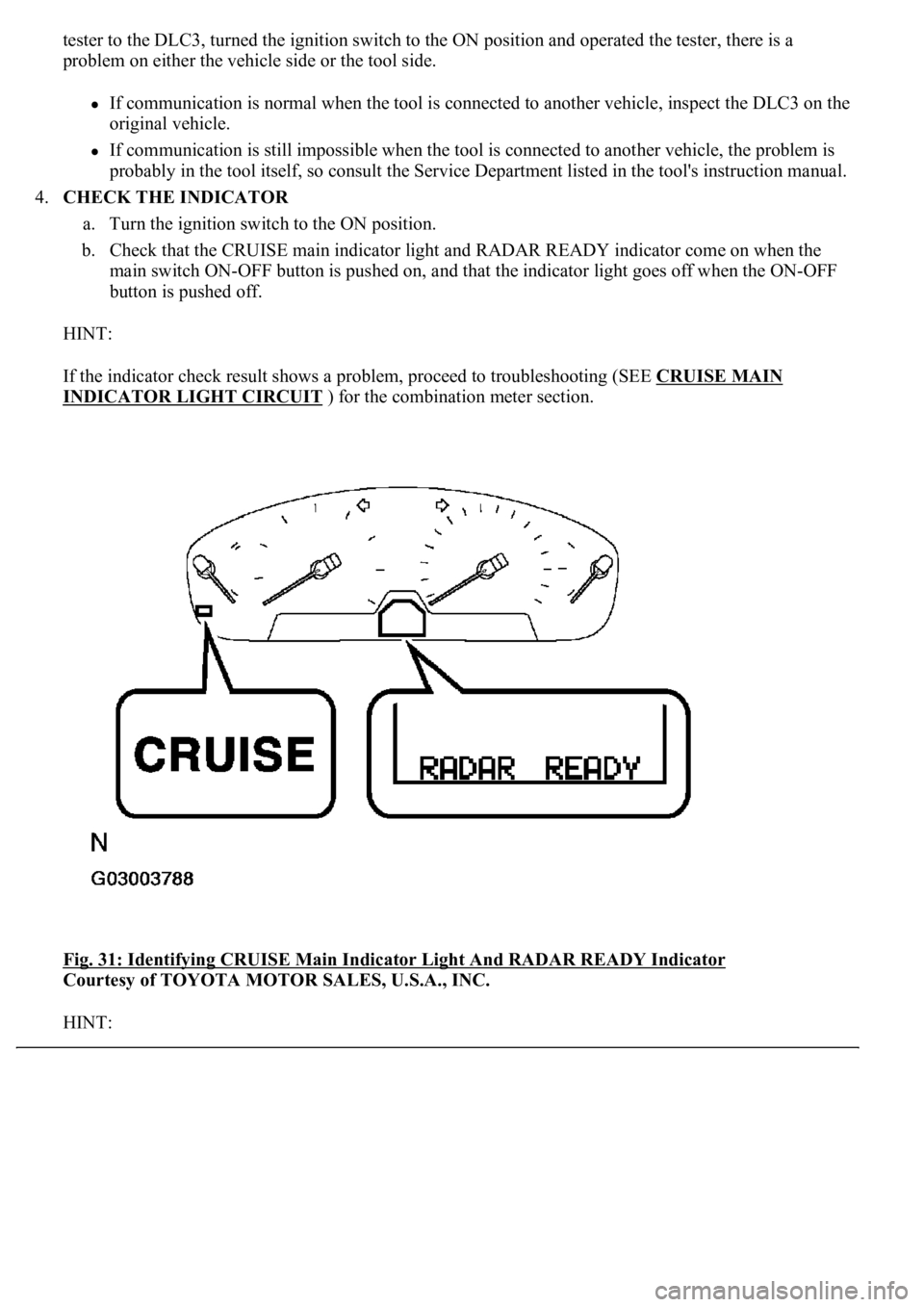
b. Check that the CRUISE main indicator light and RADAR READY indicator come on when the
main switch ON-OFF button is pushed on, and that the indicator light goes off when the ON-OFF
button is pushed off.
HINT:
If the indicator check result shows a problem, proceed to troubleshooting (SEE CRUISE MAIN
INDICATOR LIGHT CIRCUIT ) for the combination meter section.
<0029004c004a0011000300160014001d0003002c0047004800510057004c0049005c004c0051004a0003002600350038002c00360028000300300044004c00510003002c00510047004c004600440057005200550003002f004c004a004b00570003002400
51004700030035002400270024003500030035002800240027[Y Indicator
Courtesy of TOYOTA MOTOR SALES, U.S.A., INC.
HINT:
Page 2679 of 4500

a. D position test:
Shift into the D position and fully depress the accelerator pedal and check the following points.
1. Check up-shift operation.
Check that 1 --> 2,2 --> 3,3 --> 4,4 --> 5 and 5 --> 6th up-shifts take place, and that the shift
points conform to the automatic shift schedule (see SERVICE DATA
).
HINT:
6th and 5th Gear Up-shift Prohibition Control
Engine coolant temperature is 55 °C (131 °F) or less and vehicle speed is at 51 km/h
(32 mph) or less. 4th Gear Up-shift Prohibition Control
Engine coolant temperature is 47 °C (117 °F) or less and vehicle speed is at 49 km/h
(30 mph) or less. Lock-up Prohibition Control
Brake pedal is depressed.
Accelerator pedal is released.
<00280051004a004c005100480003004600520052004f0044005100570003005700480050005300480055004400570058005500480003004c00560003001900130003008300260003000b001400170013000300830029000c0003005200550003004f004800
560056001100030003[
2. Check for shift shock and slip.
Check for shock and slip at the 1 --> 2,2 --> 3, 3 --> 4, 4 --> 5 and 5 --> 6th up-shifts.
3. Check for abnormal noise and vibration.
Check for abnormal noise and vibration when up-shifting from 1 --> 2, 2 --> 3, 3 --> 4, 4 -->
5 and 5 --> 6 while driving with the shift lever in the D position, and also check while driving
in the lock-up condition.
HINT:
The check for the cause of abnormal noise and vibration must be done thoroughly as it could
also be due to loss of balance in the differential, torque converter clutch, etc.
4. Check kick-down operation.
<0026004b00480046004e000300590048004b004c0046004f004800030056005300480048004700560003005a004b0048005100030057004b004800030015005100470003005700520003001400560057000f00030016005500470003005700520003001500
510047000f000300170057004b000300570052000300160055[d, 5th to 4th, and 6th to 5th
kick-downs take place while driving with the shift lever in the D position. Confirm that each
speed is within the applicable vehicle speed range indicated in the automatic shift schedule
(see SERVICE DATA
).
5. Check for abnormal shock and slip at kic
k-down.
Page 2713 of 4500
Fig. 35: DTC Freeze Frame Specification
Courtesy of TOYOTA MOTOR SALES, U.S.A., INC.
DLC3 (Data Link Connector 3)
The vehicle's ECM uses the ISO 15765-4 for communication protocol. The terminal arrangement of the DLC3
complies with SAE J1962 and matches the ISO 15765-4 format.
HINT:
Connect the cable of the hand-held tester to the DLC3, turn the ignition switch ON and attempt to use the hand-
held tester. If the screen displays UNABLE TO CONNECT TO VEHICLE, a problem exists in the vehicle side
or the tester side.
If the communication is normal when the tool is connected to another vehicle, inspect the DLC3 on the original
vehicle.
If the communication is still impossible when the tool is connected to another vehicle, the problem is probably
in the tool itself. Consult the Service Department listed in the tool's instruction manual.
Page 3031 of 4500
Fig. 47: Removing Door Frame Garnish LH
Courtesy of TOYOTA MOTOR SALES, U.S.A., INC.
6.REMOVE FRONT DOOR SERVICE HOLE COVER LH
a. Remove the 2 screws and door electrical key oscillator.
b. Remove the service hole cover.
Page 3034 of 4500
b. Even if the flange is taken off, continue drilling and push out the remaining fragments using the
drill.
c. Using a vacuum cleaner, remove the drilled rivets and dust from the inside of the door.
Fig. 50: Removing Drilled Rivets And Dust From Inside Of Door
Courtesy of TOYOTA MOTOR SALES, U.S.A., INC.
14.REMOVE FRONT DOOR GLASS SUB-ASSY LH
HINT:
Insert a cushion inside the door panel to prevent the glass from being scratched.
a. Move the door glass until the bolts appear in the service holes.
b. Remove the 2 bolts holding the door glass to the window regulator.
Page 3036 of 4500
Fig. 52: Moving Glass
Courtesy of TOYOTA MOTOR SALES, U.S.A., INC.
15.REMOVE FRONT DOOR WINDOW REGULATOR SUB-ASSY LH
a. Disconnect the window regulator connector.
b. Remove the 6 bolts and window regulator.
HINT:
Remove the window regulator through the service hole.
Page 3039 of 4500
Fig. 55: Removing Screws And Motor
Courtesy of TOYOTA MOTOR SALES, U.S.A., INC.
17.REMOVE FRONT DOOR FRAME SUB-ASSY REAR LOWER LH
a. Remove the 2 bolts and frame.
HINT:
Remove the frame through the service hole.
Page 3040 of 4500
Fig. 56: Removing Frame Through Service Hole
Courtesy of TOYOTA MOTOR SALES, U.S.A., INC.
18.REMOVE FRONT DOOR FRAME SUB-ASSY FRONT LOWER LH
a. Remove the 2 bolts and frame.
HINT:
Remove the frame through the service hole.