Page 2315 of 4500

HINT:
See COMPONENTS
1.REMOVE INSTRUMENT PANEL UNDER COVER SUB-ASSY NO. 2
2.REMOVE INSTRUMENT PANEL GARNISH SUB-ASSY LH (See step 22 on REPLACEMENT
)
3.REMOVE INSTRUMENT PANEL FINISH PANEL (See step 26 on REPLACEMENT
)
4.REMOVE INSTRUMENT PANEL UNDER COVER SUB-ASSY NO. 1 (See step 16 on
REPLACEMENT
)
5.REMOVE INSTRUMENT PANEL SAFETY PAD SUB-ASSY NO. 1 (See step 19 on
REPLACEMENT
)
6.REMOVE CONSOLE PANEL SUB-ASSY UPPER (See step 38 on REPLACEMENT
)
7.REMOVE CONSOLE UPPER REAR PANEL SUB-ASSY (See step 39 on REPLACEMENT
)
8.REMOVE CONSOLE BOX CARPET (See step 40 on REPLACEMENT
)
9.REMOVE REAR CONSOLE ARMREST ASSY (See step 41 on REPLACEMENT
)
10.REMOVE INSTRUMENT PANEL FINISH PANEL LOWER CENTER (See step 26 on
REPLACEMENT
)
11.REMOVE INSTRUMENT CLUSTER FINISH PANEL SUB-ASSY CENTER (See step 31 on
REPLACEMENT
)
12.REMOVE CONSOLE BOX (See step 42 on REPLACEMENT
)
13.SEPARATE OXYGEN SENSOR (See REPLACEMENT
)
14.REMOVE EXHAUST PIPE ASSY
a. Remove the 4 bolts, nuts and 2 gaskets from the exhaust manifold.
b. Remove the exhaust pipe assy.
15.REMOVE FRONT FLOOR HEAT INSULATOR NO. 1
a. Remove the 4 bolts and heat insulator No. 1.
16.REMOVE PROPELLER SHAFT HEAT INSULATOR
a. Remove the 2 bolts and heat insulator.
17.REMOVE PROPELLER W/CENTER BEARING SHAFT ASSY
a. Using SST, loosen the adjusting nut until it can be turned by hand.
SST 09922-10010
HINT:
Use 2 of the same t
ype of SST.
Page 2352 of 4500
Fig. 47: Installing Heat Insulator No. 1 Bolts
Courtesy of TOYOTA MOTOR SALES, U.S.A., INC.
33.INSTALL EXHAUST PIPE ASSY (See step 7 on REPLACEMENT
)
34.INSTALL OXYGEN SENSOR (See step 8 on REPLACEMENT
)
35.CHECK FOR EXHAUST GAS LEAKS
REPLACEMENT
HINT:
See COMPONENTS
Use the same procedures for the RH side and LH side.
The procedures listed below are for the LH side.
1.REMOVE FRONT WHEELS
2.SEPARATE SKID CONTROL SENSOR WIRE
a. Disconnect the connector.
Page 2632 of 4500

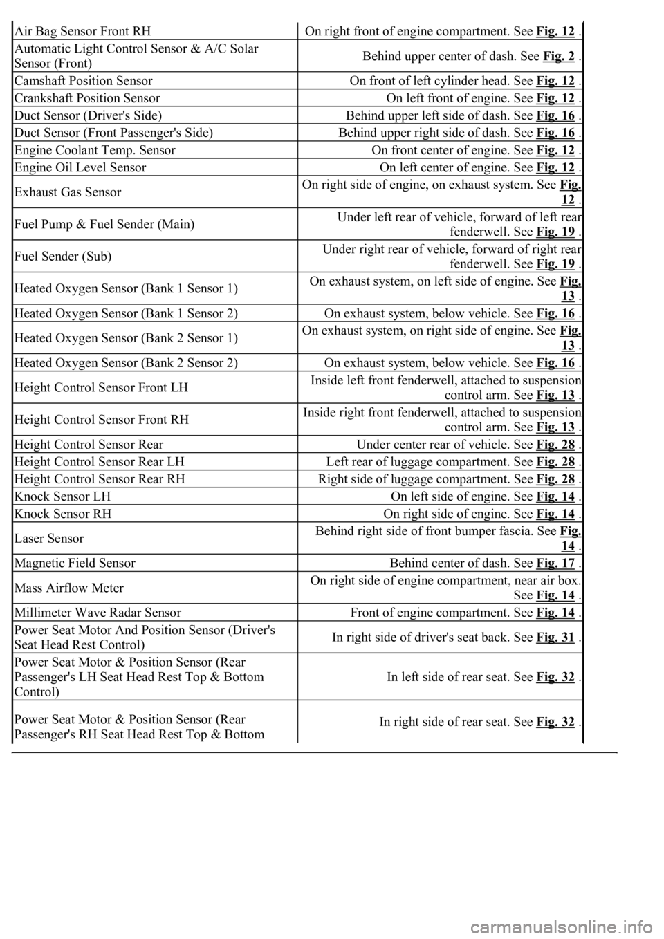
Air Bag Sensor Front RHOn right front of engine compartment. See Fig. 12 .
Automatic Light Control Sensor & A/C Solar
Sensor (Front)Behind upper center of dash. See Fig. 2 .
Camshaft Position SensorOn front of left cylinder head. See Fig. 12 .
Crankshaft Position SensorOn left front of engine. See Fig. 12 .
Duct Sensor (Driver's Side)Behind upper left side of dash. See Fig. 16 .
Duct Sensor (Front Passenger's Side)Behind upper right side of dash. See Fig. 16 .
Engine Coolant Temp. SensorOn front center of engine. See Fig. 12 .
Engine Oil Level SensorOn left center of engine. See Fig. 12 .
Exhaust Gas SensorOn right side of engine, on exhaust system. See Fig.
12 .
Fuel Pump & Fuel Sender (Main)Under left rear of vehicle, forward of left rear
fenderwell. See Fig. 19
.
Fuel Sender (Sub)Under right rear of vehicle, forward of right rear
fenderwell. See Fig. 19
.
Heated Oxygen Sensor (Bank 1 Sensor 1)On exhaust system, on left side of engine. See Fig.
13 .
Heated Oxygen Sensor (Bank 1 Sensor 2)On exhaust system, below vehicle. See Fig. 16 .
Heated Oxygen Sensor (Bank 2 Sensor 1)On exhaust system, on right side of engine. See Fig.
13 .
Heated Oxygen Sensor (Bank 2 Sensor 2)On exhaust system, below vehicle. See Fig. 16 .
Height Control Sensor Front LHInside left front fenderwell, attached to suspension
control arm. See Fig. 13
.
Height Control Sensor Front RHInside right front fenderwell, attached to suspension
control arm. See Fig. 13
.
Height Control Sensor RearUnder center rear of vehicle. See Fig. 28 .
Height Control Sensor Rear LHLeft rear of luggage compartment. See Fig. 28 .
Height Control Sensor Rear RHRight side of luggage compartment. See Fig. 28 .
Knock Sensor LHOn left side of engine. See Fig. 14 .
Knock Sensor RHOn right side of engine. See Fig. 14 .
Laser SensorBehind right side of front bumper fascia. See Fig.
14 .
Magnetic Field SensorBehind center of dash. See Fig. 17 .
Mass Airflow MeterOn right side of engine compartment, near air box.
See Fig. 14
.
Millimeter Wave Radar SensorFront of engine compartment. See Fig. 14 .
Power Seat Motor And Position Sensor (Driver's
Seat Head Rest Control)In right side of driver's seat back. See Fig. 31 .
Power Seat Motor & Position Sensor (Rear
Passenger's LH Seat Head Rest Top & Bottom
Control)
In left side of rear seat. See Fig. 32 .
Power Seat Motor & Position Sensor (Rear
Passenger's RH Seat Head Rest Top & Bottom In right side of rear seat. See Fig. 32 .
Page 2670 of 4500

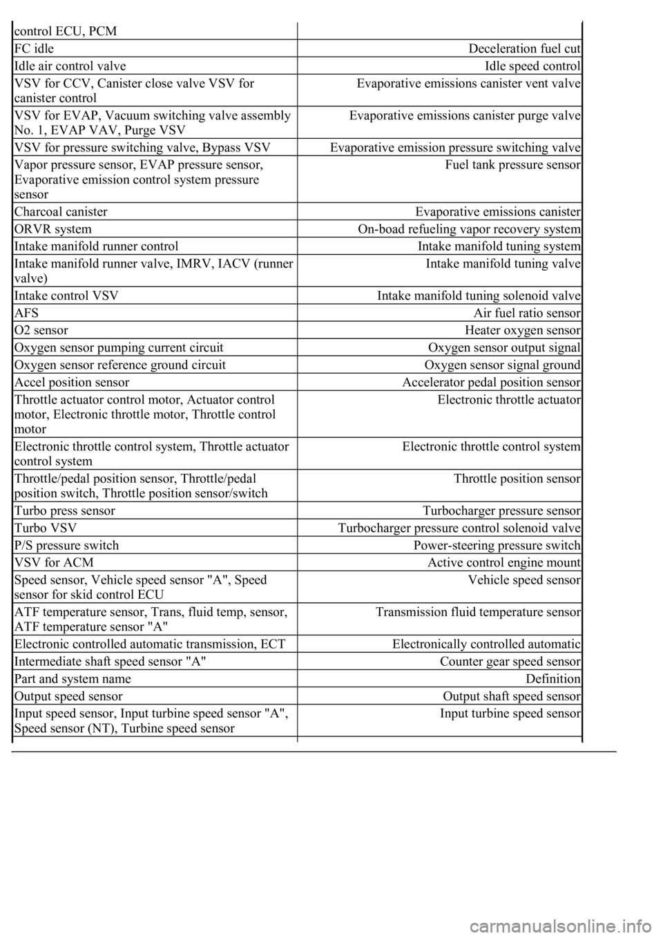
control ECU, PCM
FC idleDeceleration fuel cut
Idle air control valveIdle speed control
VSV for CCV, Canister close valve VSV for
canister controlEvaporative emissions canister vent valve
VSV for EVAP, Vacuum switching valve assembly
No. 1, EVAP VAV, Purge VSVEvaporative emissions canister purge valve
VSV for pressure switching valve, Bypass VSVEvaporative emission pressure switching valve
Vapor pressure sensor, EVAP pressure sensor,
Evaporative emission control system pressure
sensorFuel tank pressure sensor
Charcoal canisterEvaporative emissions canister
ORVR systemOn-boad refueling vapor recovery system
Intake manifold runner controlIntake manifold tuning system
Intake manifold runner valve, IMRV, IACV (runner
valve)Intake manifold tuning valve
Intake control VSVIntake manifold tuning solenoid valve
AFSAir fuel ratio sensor
O2 sensorHeater oxygen sensor
Oxygen sensor pumping current circuitOxygen sensor output signal
Oxygen sensor reference ground circuitOxygen sensor signal ground
Accel position sensorAccelerator pedal position sensor
Throttle actuator control motor, Actuator control
motor, Electronic throttle motor, Throttle control
motorElectronic throttle actuator
Electronic throttle control system, Throttle actuator
control systemElectronic throttle control system
Throttle/pedal position sensor, Throttle/pedal
position switch, Throttle position sensor/switchThrottle position sensor
Turbo press sensorTurbocharger pressure sensor
Turbo VSVTurbocharger pressure control solenoid valve
P/S pressure switchPower-steering pressure switch
VSV for ACMActive control engine mount
Speed sensor, Vehicle speed sensor "A", Speed
sensor for skid control ECUVehicle speed sensor
ATF temperature sensor, Trans, fluid temp, sensor,
ATF temperature sensor "A"Transmission fluid temperature sensor
Electronic controlled automatic transmission, ECTElectronically controlled automatic
Intermediate shaft speed sensor "A"Counter gear speed sensor
Part and system nameDefinition
Output speed sensorOutput shaft speed sensor
<002c00510053005800570003005600530048004800470003005600480051005600520055000f0003002c005100530058005700030057005800550045004c005100480003005600530048004800470003005600480051005600520055000300050024000500
0f0003[
Speed sensor (NT), Turbine speed sensorInput turbine speed sensor
Page 2906 of 4500
EVAP-VSV
EVAP Vacuum Switching Valve
FR
Fill Pipe Restrictor
HO2S
Heated Oxygen Sensor
MIL
Malfunction Indicator Light
ORVR-COV
On-Board Refueling Vapor Recovery Cut-Off Valve
ORVR-OCKV
On-Board Refueling Vapor Recovery Overfill Check Valve
PCV
Positive Crankcase Ventilation
SFI
Sequential Multiport Fuel Injection
SPK-CC
SPK Computer Controlled
TWC
Three-Way Catalytic Converter
WU-TWC
Warm-Up Three-Wa
y Catalytic Converter
Page 2912 of 4500
c. Warm up the heated oxygen sensor with the engine speed at 2,500 rpm for approximately 2
minutes.
d. Check that the voltage changes between 0 and 1 V with the engine speed at 2,500 rpm.
OK: The voltage has changed more than 8 times in 10 seconds.
Fig. 6: Inspecting A/F Compensation System
Courtesy of TOYOTA MOTOR SALES, U.S.A., INC.
2.INSPECT FUEL CUT OFF RPM
a. Increase the engine speed to at least 3,000 rpm.
b. Use a sound scope to check the injector operation noise.
OK: When the throttle lever is released, the injector operation noise stops momentarily but
starts again soon after.
Page 2914 of 4500
Fig. 8: Checking Cracks, Leaks Or Damage
Courtesy of TOYOTA MOTOR SALES, U.S.A., INC.
5.INSPECT HEATED OXYGEN SENSOR (HEATER RESISTANCE)
a. Bank 1 sensor 1, bank 2 sensor 1:
Disconnect the sensor connector.
b. Measure the resistance between terminals 1 (HT) and 2 (+B).
Standard:
RESISTANCE CONDITION
If the result is not as specified, replace the sensor.
ConditionSpecified Condition
20°C (68°F)11 to 16 ohms
Page 2915 of 4500
Fig. 9: Identifying Connector Terminals Heated Oxygen Sensor
Courtesy of TOYOTA MOTOR SALES, U.S.A., INC.
c. Bank 1 sensor 2, bank 2 sensor 2:
Disconnect the sensor connector.
d. Measure the resistance between terminals 1 (HT) and 2 (+B).
Standard:
RESISTANCE CONDITION
If the result is not as specified, replace the sensor.
ConditionSpecified Condition
20°C (68°F)11 to 16 ohms