Page 2043 of 4500
c. Check the oil level.
d. Using a hexagon wrench (10 mm), install the rear differential filler plug with a new gasket.
Torque: 49 N.m (500 kgf.cm, 36 ft.lbf)
REPLACEMENT
HINT:
See COMPONENTS
Use the same procedures for the RH side and LH side.
1.REMOVE REAR WHEEL
2.REMOVE REAR DIFFERENTIAL FILLER PLUG
a. Using a hexagon wrench (10 mm), remove the filler plug and gasket.
3.REMOVE REAR DIFFERENTIAL DRAIN PLUG
a. Using a hexagon wrench (10 mm), remove the drain plug and gasket.
b. Drain the differential oil.
4.REMOVE REAR DRIVE SHAFT ASSY LH (SEE REPLACEMENT
)
5.REMOVE REAR DIFFERENTIAL SIDE GEAR SHAFT OIL SEAL
a. Using SST, remove the oil seal.
SST 09308-10010
Page 2045 of 4500

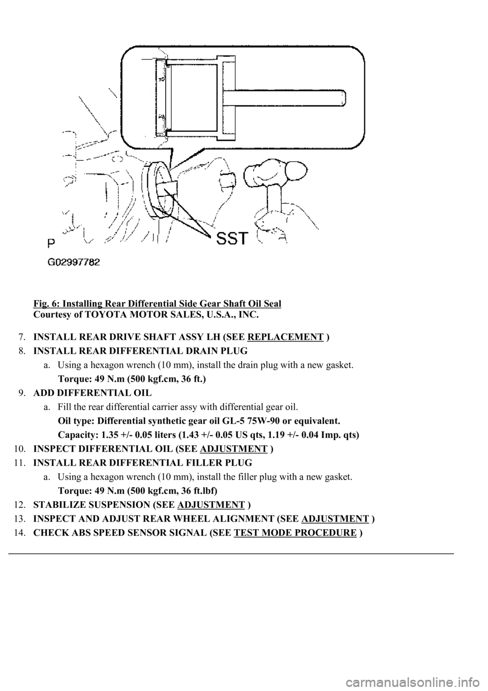
Fig. 6: Installing Rear Differential Side Gear Shaft Oil Seal
Courtesy of TOYOTA MOTOR SALES, U.S.A., INC.
7.INSTALL REAR DRIVE SHAFT ASSY LH (SEE REPLACEMENT
)
8.INSTALL REAR DIFFERENTIAL DRAIN PLUG
a. Using a hexagon wrench (10 mm), install the drain plug with a new gasket.
Torque: 49 N.m (500 kgf.cm, 36 ft.)
9.ADD DIFFERENTIAL OIL
a. Fill the rear differential carrier assy with differential gear oil.
Oil type: Differential synthetic gear oil GL-5 75W-90 or equivalent.
<00260044005300440046004c0057005c001d000300140011001600180003000e00120010000300130011001300180003004f004c00570048005500560003000b00140011001700160003000e00120010000300130011001300180003003800360003005400
570056000f0003001400110014001c0003000e001200100003[0.04 Imp. qts)
10.INSPECT DIFFERENTIAL OIL (SEE ADJUSTMENT
)
11.INSTALL REAR DIFFERENTIAL FILLER PLUG
a. Using a hexagon wrench (10 mm), install the filler plug with a new gasket.
Torque: 49 N.m (500 kgf.cm, 36 ft.lbf)
12.STABILIZE SUSPENSION (SEE ADJUSTMENT
)
13.INSPECT AND ADJUST REAR WHEEL ALIGNMENT (SEE ADJUSTMENT
)
14.CHECK ABS SPEED SENSOR SIGNAL (SEE TEST MODE PROCEDURE
)
Page 2163 of 4500
Tighten the nut using approximately 98 N.m (1,000 kgf.cm) of force and then tighten it further
while observing the preload.
d. Even if the nut tightening torque is greater than the specified maximum value, if the preload is less
than the specified minimum value, loosen the nut and check that the threads of the nut and drive
pinion are not stripped.
e. If the threads are not stripped, replace the spacer and apply hypoid gear oil LSD to the threads and
repeat the procedure.
54.INSPECT RUNOUT OF DIFFERENTIAL DRIVE PINION
a. Place a dial indicator where 10 mm (0.39 in.) away from the drive pinion shaft tip at a right angle.
b. Measure the shaft runout.
Maximum runout: 0.08 mm (0.0031 in.)
Fig. 123: Inspecting Differential Drive Pinion Runout
Courtesy of TOYOTA MOTOR SALES, U.S.A., INC.
55.INSTALL REAR DIFFERENTIAL SIDE GEAR SHAFT OIL SEAL
a. Appl
y MP grease to the 2 new oil seal lips.
Page 2164 of 4500
b. Using SST and a hammer, tap a new oil seal until the face becomes flush with the differential
carrier surface.
SST 09223-15030, 09950-70010 (09951-07200)
Fig. 124: Installing Rear Differential Side Gear Shaft Oil Seal
Courtesy of TOYOTA MOTOR SALES, U.S.A., INC.
56.INSPECT TOTAL PRELOAD
a. Using SST and a torque wrench, check the torque (at starting) with the drive pinion and ring gear
teeth in contact.
SST 09229-55010
Total preload (at starting):
Drive pinion preload plus 0.46 to 1.37 N.m
(4.69 to 13.97 kgf.cm, 4.07 to 12.13 in..lbf)
Page 2177 of 4500

a. Fill the rear differential carrier assy with differential gear oil equivalent.
Oil type: Differential synthetic gear oil GL-5 75W-90 or equivalent
Capacity: 1.35 +/- 0.05 liters (1.43 +/- 0.05 US qts, 1.19 +/- 0.04 Imp. qts)
67.INSPECT DIFFERENTIAL OIL (SEE ADJUSTMENT
)
68.INSTALL REAR DIFFERENTIAL FILLER PLUG
a. Using a hexagon wrench (10 mm), install the filler plug with a new gasket.
Torque: 49 N.m (500 kgf.cm, 36 ft.lbf)
69.INSTALL REAR DRIVE SHAFT ASSY LH (SEE REPLACEMENT
)
70.INSTALL REAR DRIVE SHAFT ASSY RH
HINT:
Installation procedure of the RH side is the same as that of the LH side.
71.INSTALL FRONT FLOOR HEAT INSULATOR NO.1
a. Install the front floor heat insulator No.1 with the 4 bolts.
Torque: 5.4 N.m (55 kgf.cm, 48 in..lbf)
72.INSTALL REAR WHEEL
a. Install the rear wheel with the 5 nuts.
Torque: 103 N.m (1,050 kgf.cm, 76 ft.lbf)
73. Install the ornament with the 10 bolts.
Torque: 20 N.m (204 kgf.cm, 15 ft.lbf)
74.INSTALL PROPELLER W/CENTER BEARING SHAFT ASSY (SEE OVERHAUL
)
75.FULLY TIGHTEN CENTER SUPPORT BEARING ASSY NO.1 (SEE OVERHAUL
)
SST 09922-10010
76.INSPECT AND ADJUST NO.2 AND NO.3 JOINT ANGLE (SEE OVERHAUL
)
77.INSTALL PROPELLER SHAFT HEAT INSULATOR (SEE OVERHAUL
)
78.INSTALL EXHAUST PIPE ASSY (SEE REPLACEMENT
)
79.INSTALL OXYGEN SENSOR (SEE REPLACEMENT
)
80.INSPECT AND ADJUST REAR WHEEL ALIGNMENT (SEE ADJUSTMENT
)
81.ADJUST VEHICLE HEIGHT (W/ AIR SUSPENSION) (SEE ON
-VEHICLE INSPECTION )
82.INSPECT HEADLIGHT AIM ONLY (SEE ADJUSTMENT
)
83.CHECK ABS SPEED SENSOR SIGNAL (SEE TEST MODE PROCEDURE
)
84.INSPECT AIR LEAK (W/ AIR SUSPENSION) (SEE REPLACEMENT
)
HINT:
Perform this operation onl
y when the rear differential mount cushion is replaced.
Page 2377 of 4500
Fig. 71: Removing Rear Drive Shaft Assy LH
Courtesy of TOYOTA MOTOR SALES, U.S.A., INC.
17.INSPECT REAR DRIVE SHAFT ASSY LH
a. Check that there is no excessive play in the outboard joint.
b. Check if the inboard joint slides smoothly in the thrust direction.
c. Check that there is no excessive play in the radial direction of the inboard joint.
d. Check the boots for damage.
18.INSTALL REAR DRIVE SHAFT ASSY LH
a. Coat the spline of the inboard joint shaft assy with gear oil.
b. Align the shaft splines, install the drive shaft assy LH with a brass bar and a hammer.
HINT:
Page 2745 of 4500

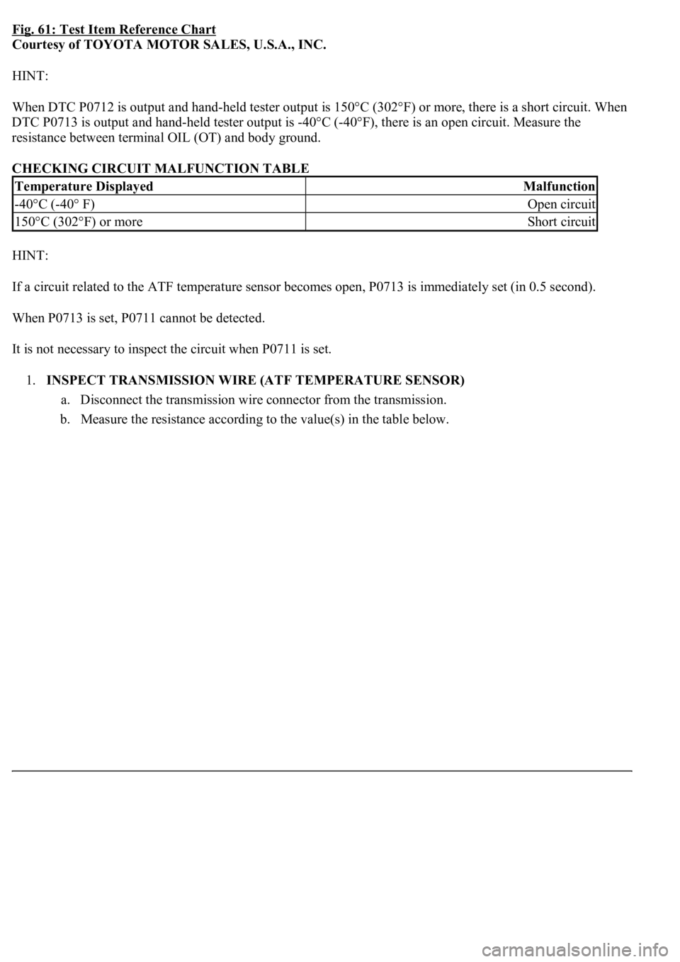
Fig. 61: Test Item Reference Chart
Courtesy of TOYOTA MOTOR SALES, U.S.A., INC.
HINT:
<003a004b004800510003002700370026000300330013001a001400150003004c0056000300520058005700530058005700030044005100470003004b0044005100470010004b0048004f004700030057004800560057004800550003005200580057005300
5800570003004c00560003001400180013008300260003000b[302°F) or more, there is a short circuit. When
DTC P0713 is output and hand-held tester output is -40°C (-40°F), there is an open circuit. Measure the
resistance between terminal OIL (OT) and body ground.
CHECKING CIRCUIT MALFUNCTION TABLE
HINT:
If a circuit related to the ATF temperature sensor becomes open, P0713 is immediately set (in 0.5 second).
When P0713 is set, P0711 cannot be detected.
It is not necessary to inspect the circuit when P0711 is set.
1.INSPECT TRANSMISSION WIRE (ATF TEMPERATURE SENSOR)
a. Disconnect the transmission wire connector from the transmission.
b. Measure the resistance according to the value(s) in the table below.
Temperature DisplayedMalfunction
-40°C (-40° F)Open circuit
150°C (302°F) or moreShort circuit
Page 2747 of 4500
Fig. 63: Transmission Wire Connector Reference Chart
Courtesy of TOYOTA MOTOR SALES, U.S.A., INC.
NG: REPAIR OR REPLACE TRANSMISSION WIRE (See step 5 on REPLACEMENT
)
OK: Go to next step
2.CHECK HARNESS AND CONNECTOR (TRANSMISSION WIRE - ECM)
a. Connect the transmission wire connector to the transmission.
b. Disconnect the ECM connector.
c. Measure the resistance according to the value(s) in the table below.
Standard:
TRANSMISSION WIRE - ECM - RESISTANCE TABLE
d. Measure the resistance according to the value(s) in the table below.
Fig. 64: Disconnecting ECM Connector
Tester ConnectionSpecified Condition
E6 - 27 (OIL) - E6 - 26 (EOIL)79ohms to 156kohms