Page 48 of 4500
SST 09843-18040
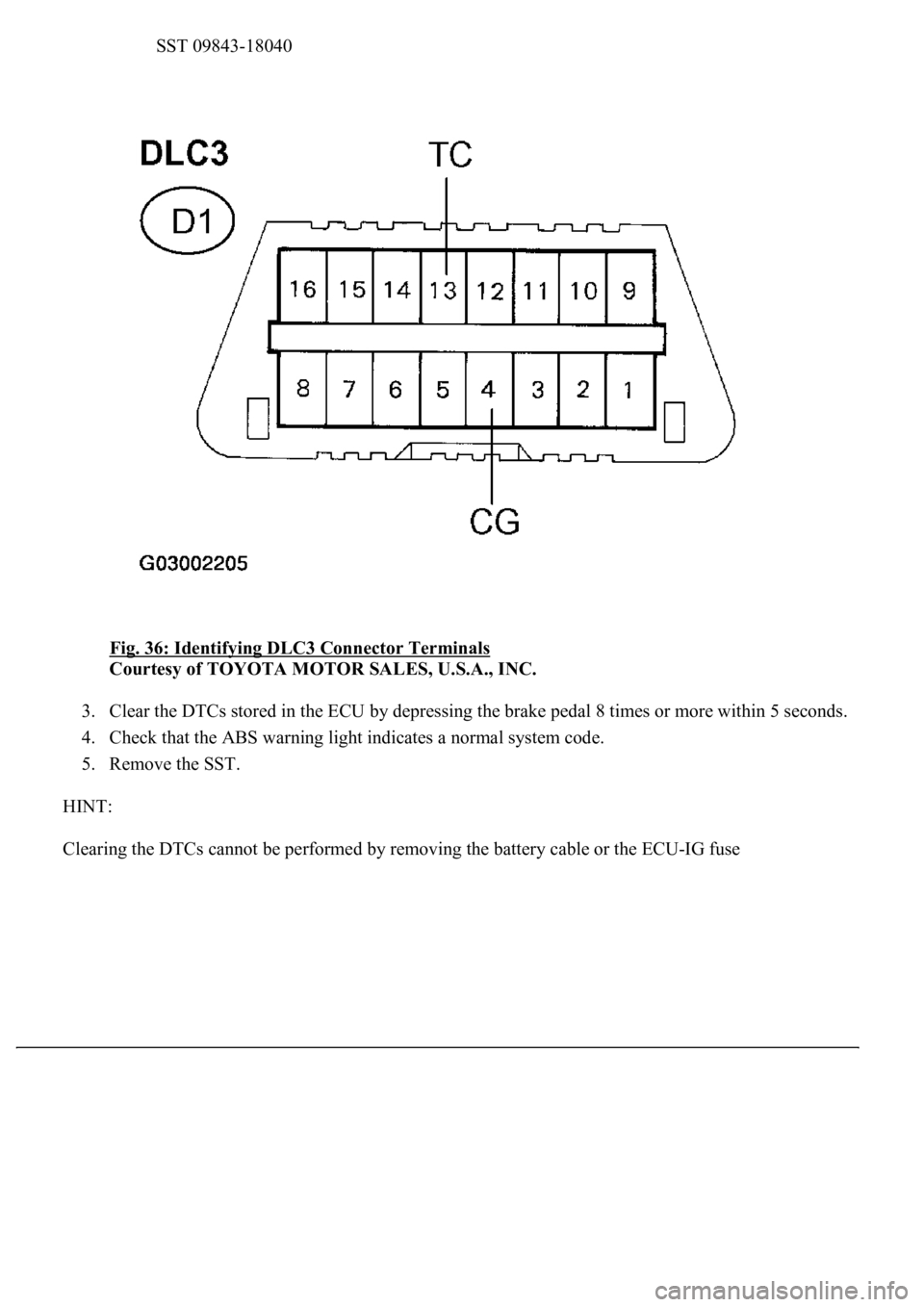
Fig. 36: Identifying DLC3 Connector Terminals
Courtesy of TOYOTA MOTOR SALES, U.S.A., INC.
3. Clear the DTCs stored in the ECU by depressing the brake pedal 8 times or more within 5 seconds.
4. Check that the ABS warning light indicates a normal system code.
5. Remove the SST.
HINT:
Clearin
g the DTCs cannot be performed by removing the battery cable or the ECU-IG fuse
Page 55 of 4500

HINT:
If a malfunction code is displayed during the DTC check, check the circuit indicated by the table below.
DIAGNOSTIC TROUBLE CODE CHART
SMF (BA-SOL)Turns TRAC solenoid SMF (BA-SOL)
ON / OFFOperation of solenoid (clicking sound)
can be heard
SMRTurns TRAC solenoid SMR ON / OFFOperation of solenoid (clicking sound)
can be heard
SOL RELAYTurns ABS solenoid relay ON / OFFOperation of solenoid (clicking sound)
can be heard
ABS MOT RELAYTurns ABS motor relay ON / OFFOperation of solenoid (clicking sound)
can be heard
ABS WARN LIGHTTurns ABS warning light ON / OFFObserve combination meter
VSC WARN LIGHTTurns VSC warning light ON / OFFObserve combination meter
VSC / TRC OFF INDTurns VSC / TRC OFF indicator ON /
OFFObserve combination meter
SLIP INDI LIGHTTurns SLIP indicator light ON / OFFObserve combination meter
BRAKE WRN LIGHTTurns BRAKE warning light ON / OFFObserve combination meter
VSC / BR WARN
BUZTurns VSC / BRAKE warning buzzer
ON / OFFBuzzer can be heard
STP LIGHT RELAYTurns stop light ON / OFFStop light come on
DTCDescription
DTC C0200/31, C0205/32RIGHT/LEFT FRONT SPEED SENSOR
DTC C0210/33, C0215/34RIGHT/LEFT REAR SPEED SENSOR
DTC C0226/21, C0236/22, C0246/23,
C0256/24, C1225/25
SFR/SFL/SRR/SRL/SM SOLENOID CIRCUIT
DTC C0273/13, C0274/14, C1361/91OPEN CIRCUIT IN ABS MOTOR RELAY CIRCUIT,
B+ SHORT CIRCUIT IN ABS MOTOR RELAY
CIRCUIT, SHORT CIRCUIT IN ABS MOTOR FAIL
SAFE RELAY CIRCUIT
DTC C0278/11, C0279/12OPEN/SHORT CIRCUIT IN ABS SOLENOID
RELAY CIRCUIT
DTC C1201/51ENGINE CONTROL SYSTEM MALFUNCTION
DTC C1203/53ECM COMMUNICATION CIRCUIT
MALFUNCTION
DTC C1210/36, C1336/39ZERO POINT CALIBRATION OF YAW
RATE/DECELERATION SENSOR UNDONE
DTC C1223/43ABS CONTROL SYSTEM MALFUNCTION
DTC C1231/31MALFUNCTION IN STEERING ANGLE SENSOR
CIRCUIT
Page 56 of 4500
DTC chart of ABS:
DTC C1232/32, C1234/34, C1243/43,
C1244/44, C1245/45, C1381/97
MALFUNCTION IN DECELERATION/YAW RATE
SENSOR, OPEN OR SHORT IN DECELERATION
SENSOR CIRCUIT, MALFUNCTION IN POWER
SUPPLY VOLTAGE YAW/DECELERATION
SENSOR
DTC C1235/35, C1236/36, C1238/38,
C1239/39
FOREIGN MATTER IS ATTACHED ON TIP OF
RIGHT/LEFT FRONT/REAR SENSOR
DTC C1241/41LOW BATTERY POSITIVE VOLTAGE
DTC C1246/46MALFUNCTION IN MASTER CYLINDER
PRESSURE SENSOR
DTC C1249/49OPEN CIRCUIT IN STOP LIGHT SWITCH CIRCUIT
DTC C1251/51PUMP MOTOR IS LOCKED/OPEN CIRCUIT IN
PUMP MOTOR GROUND
DTC C1267/67Brake Pedal Load Sensing Switch
Page 59 of 4500
*2:
1. Keep the vehicle in the stationary condition for 5 seconds or more and depress the brake pedal
lightly 2 or 3 times.
2. Drive the vehicle at the vehicle speed of 31 mph (50 km/h) and keep depressing the brake pedal
strongly for approximately 3 seconds.
3. Repeat the above operation 3 times or more and check that the ABS warning light goes off.
4. Clear the DTC (see DTC CHECK/CLEAR
).
HINT:
In some cases, the hand-held tester cannot be used when ABS warning light remains on.
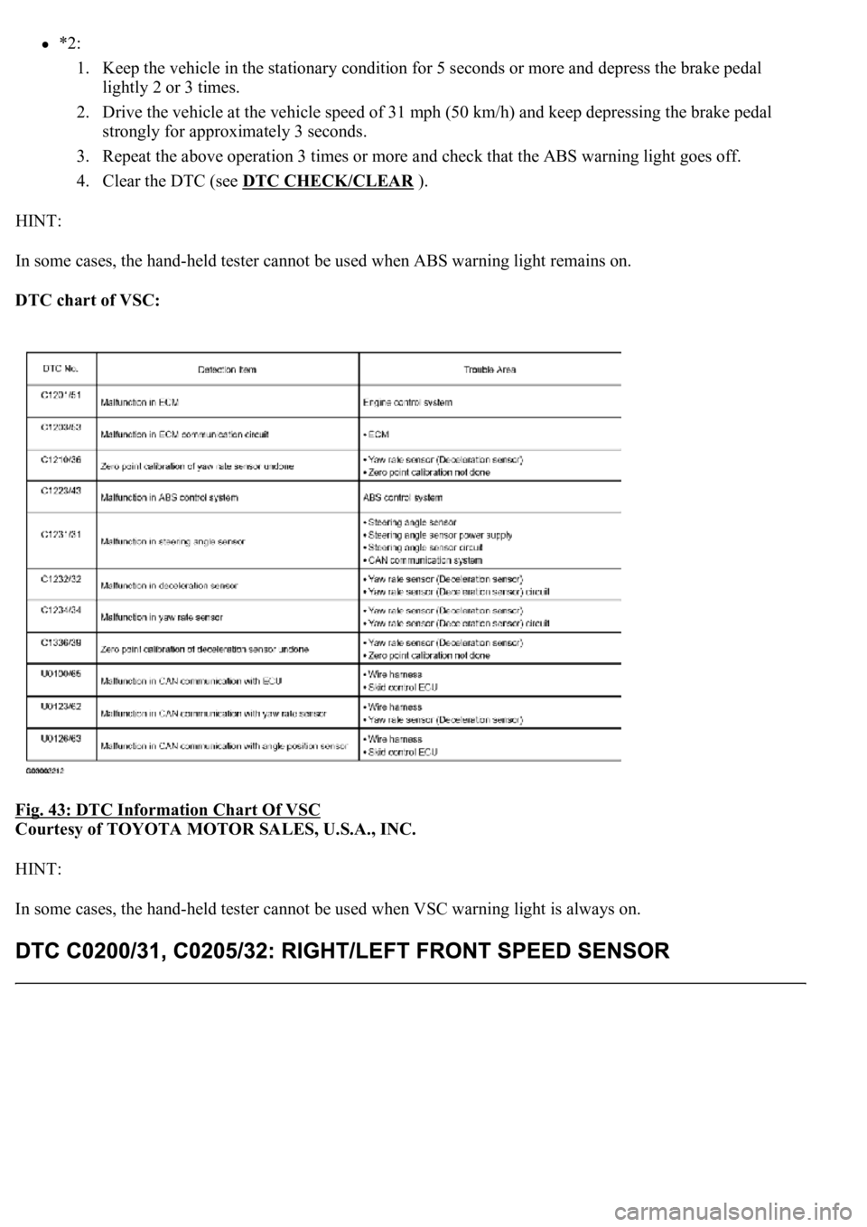
DTC chart of VSC:
Fig. 43: DTC Information Chart Of VSC
Courtesy of TOYOTA MOTOR SALES, U.S.A., INC.
HINT:
In some cases, the hand-held tester cannot be used when VSC warning light is always on.
Page 128 of 4500

c. Select the DATA LIST mode on the hand-held tester.
MEASUREMENT ITEM / RANGE (DISPLAY) DESCRIPTION
d. Check that the brake fluid pressure value of the master cylinder pressure sensor observed in the
hand held tester changes when the brake pedal is depressed.
OK: Go to next step
When the pedal is depressed, displayed voltage on the hand-held tester increases.
NG: Go to step 2
OK: REPLACE ABS & TRACTION ACTUATOR ASSY (SEE REPLACEMENT
)
2.INSPECT SKID CONTROL ECU TERMINAL VOLTAGE (STP TERMINAL)
a. Disconnect the skid control ECU connector.
b. Measure the voltage according to the value (s) in the table below.
Standard:
TESTER CONNECTION SPECIFIED CONDITION
NG: CHECK AND REPLACE STOP LIGHT SWITCH CIRCUIT
OK: REPLACE ABS & TRACTION ACTUATOR ASSY (SEE REPLACEMENT
)
ItemMeasurement Item / Range (Display)Normal Condition
MAS CYL PRS
1Master cylinder pressure sensor 1 reading /
min.: 0 V, max.: 5 VWhen brake pedal is released:
0.3 to 0.9V
Tester ConnectionSwitch ConditionSpecified Condition
S42-27 (STP) - Body groundBrake pedal depressed8 to 14V
S42-27 (STP) - Body groundBrake pedal releasedBelow 1 V
Page 130 of 4500
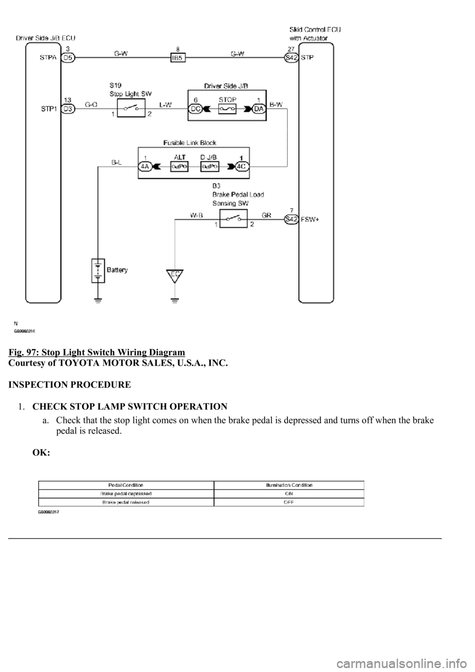
Fig. 97: Stop Light Switch Wiring Diagram
Courtesy of TOYOTA MOTOR SALES, U.S.A., INC.
INSPECTION PROCEDURE
1.CHECK STOP LAMP SWITCH OPERATION
a. Check that the stop light comes on when the brake pedal is depressed and turns off when the brake
pedal is released.
OK:
Page 162 of 4500
CIRCUIT DESCRIPTION
The BRAKE warning light comes on when the brake fluid is insufficient, the parking brake is applied or the
EBD is defective.
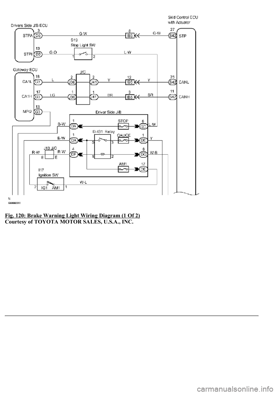
The skid control ECU is connected to the combination meter via CAN and Multiplex communications.
The pad wear indicator is installed to the brake pad (right side).
If the wear indicator wire is open, "Brake Wear" appears on the multi-information display, which indicates that
the pad must be replaced.
WIRING DIAGRAM
Page 163 of 4500
Fig. 120: Brake Warning Light Wiring Diagram (1 Of 2)
Courtesy of TOYOTA MOTOR SALES, U.S.A., INC.