Page 1022 of 4500
pedal reserve distance.
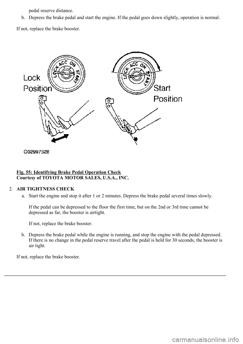
b. Depress the brake pedal and start the engine. If the pedal goes down slightly, operation is normal.
If not, replace the brake booster.
Fig. 55: Identifying Brake Pedal Operation Check
Courtesy of TOYOTA MOTOR SALES, U.S.A., INC.
2.AIR TIGHTNESS CHECK
a. Start the engine and stop it after 1 or 2 minutes. Depress the brake pedal several times slowly.
If the pedal can be depressed to the floor the first time, but on the 2nd or 3rd time cannot be
depressed as far, the booster is airtight.
If not, replace the brake booster.
b. Depress the brake pedal while the engine is running, and stop the engine with the pedal depressed.
If there is no change in the pedal reserve travel after the pedal is held for 30 seconds, the booster is
air tight.
If not, replace the brake booster.
Page 1108 of 4500
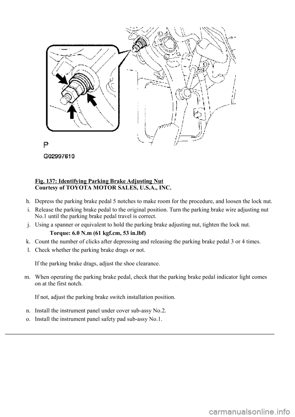
Fig. 137: Identifying Parking Brake Adjusting Nut
Courtesy of TOYOTA MOTOR SALES, U.S.A., INC.
h. Depress the parking brake pedal 5 notches to make room for the procedure, and loosen the lock nut.
i. Release the parking brake pedal to the original position. Turn the parking brake wire adjusting nut
<00310052001100140003005800510057004c004f00030057004b00480003005300440055004e004c0051004a0003004500550044004e004800030053004800470044004f000300570055004400590048004f0003004c005600030046005200550055004800
460057001100030003[
j. Using a spanner or equivalent to hold the parking brake adjusting nut, tighten the lock nut.
Torque: 6.0 N.m (61 kgf.cm, 53 in.lbf)
k. Count the number of clicks after depressing and releasing the parking brake pedal 3 or 4 times.
l. Check whether the parking brake drags or not.
If the parking brake drags, adjust the shoe clearance.
m. When operating the parking brake pedal, check that the parking brake pedal indicator light comes
on at the first notch.
If not, adjust the parking brake switch installation position.
n. Install the instrument panel under cover sub-assy No.2.
o. Install the instrument panel safet
y pad sub-assy No.1.
Page 1128 of 4500
30.INSPECT SRS WARNING LIGHT (SEE DIAGNOSIS SYSTEM )
31.PERFORM INITIALIZATION (SEE INITIALIZATION
)
COMPONENTS
Fig. 156: Exploded View Of Parking Brake Cable Assy No.1
Courtesy of TOYOTA MOTOR SALES, U.S.A., INC.
Page 1147 of 4500
73.INSPECT PARKING BRAKE PEDAL TRAVEL (SEE ADJUSTMENT )
74.ADJUST PARKING BRAKE PEDAL TRAVEL (SEE ADJUSTMENT
)
75.INSTALL INSTRUMENT PANEL UNDER COVER SUB-ASSY NO.2 (SEE REPLACEMENT
)
76.INSTALL INSTRUMENT PANEL AIR BAG ASSY LOWER NO.1 (SEE REPLACEMENT
)
77.INSTALL INSTRUMENT PANEL SAFETY PAD SUB-ASSY NO.1 (SEE REPLACEMENT
)
78.INSTALL OUTER MIRROR SWITCH ASSY
79.INSTALL COIN BOX ASSY
80.INSTALL INSTRUMENT PANEL UNDER COVER SUB-ASSY NO.1 (SEE REPLACEMENT
)
81.INSTALL INSTRUMENT CLUSTER FINISH PANEL CENTER LOWER
82.INSTALL INSTRUMENT CLUSTER FINISH PANEL END
83.CONNECT BATTERY NEGATIVE TERMINAL
84.INSPECT SRS WARNING LIGHT (SEE DIAGNOSIS SYSTEM
)
85.CHECK FOR EXHAUST GAS LEAKS
86.PERFORM YAWRATE SENSOR ZERO POINT CALIBRATION (SEE CALIBRATION
)
87.PERFORM INITIALIZATION (SEE INITIALIZATION
)
COMPONENTS
Page 1744 of 4500
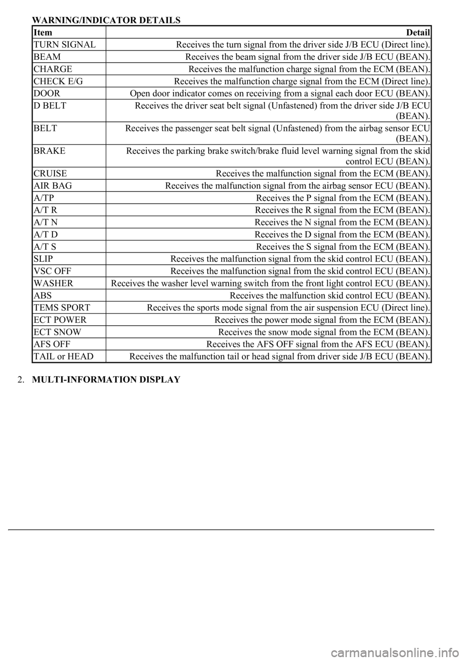
WARNING/INDICATOR DETAILS
2.MULTI-INFORMATION DISPLAY
ItemDetail
TURN SIGNALReceives the turn signal from the driver side J/B ECU (Direct line).
BEAMReceives the beam signal from the driver side J/B ECU (BEAN).
CHARGEReceives the malfunction charge signal from the ECM (BEAN).
CHECK E/GReceives the malfunction charge signal from the ECM (Direct line).
DOOROpen door indicator comes on receiving from a signal each door ECU (BEAN).
D BELTReceives the driver seat belt signal (Unfastened) from the driver side J/B ECU
(BEAN).
BELTReceives the passenger seat belt signal (Unfastened) from the airbag sensor ECU
(BEAN).
BRAKEReceives the parking brake switch/brake fluid level warning signal from the skid
control ECU (BEAN).
CRUISEReceives the malfunction signal from the ECM (BEAN).
AIR BAGReceives the malfunction signal from the airbag sensor ECU (BEAN).
A/TPReceives the P signal from the ECM (BEAN).
A/T RReceives the R signal from the ECM (BEAN).
A/T NReceives the N signal from the ECM (BEAN).
A/T DReceives the D signal from the ECM (BEAN).
A/T SReceives the S signal from the ECM (BEAN).
SLIPReceives the malfunction signal from the skid control ECU (BEAN).
VSC OFFReceives the malfunction signal from the skid control ECU (BEAN).
WASHERReceives the washer level warning switch from the front light control ECU (BEAN).
ABSReceives the malfunction skid control ECU (BEAN).
TEMS SPORTReceives the sports mode signal from the air suspension ECU (Direct line).
ECT POWERReceives the power mode signal from the ECM (BEAN).
ECT SNOWReceives the snow mode signal from the ECM (BEAN).
AFS OFFReceives the AFS OFF signal from the AFS ECU (BEAN).
TAIL or HEADReceives the malfunction tail or head signal from driver side J/B ECU (BEAN).
Page 1775 of 4500
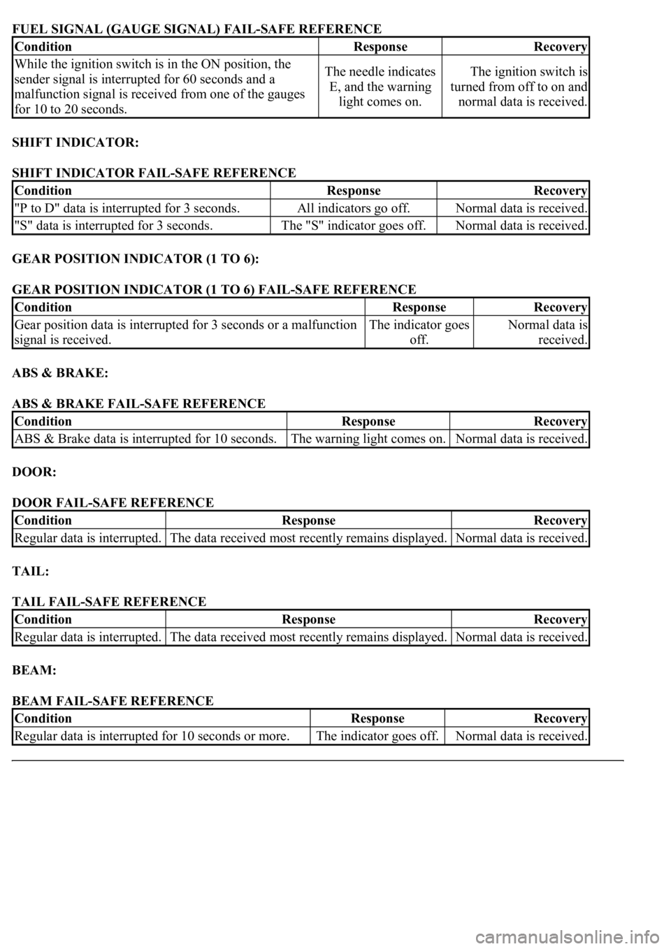
FUEL SIGNAL (GAUGE SIGNAL) FAIL-SAFE REFERENCE
SHIFT INDICATOR:
SHIFT INDICATOR FAIL-SAFE REFERENCE
GEAR POSITION INDICATOR (1 TO 6):
GEAR POSITION INDICATOR (1 TO 6) FAIL-SAFE REFERENCE
ABS & BRAKE:
ABS & BRAKE FAIL-SAFE REFERENCE
DOOR:
DOOR FAIL-SAFE REFERENCE
TAIL:
TAIL FAIL-SAFE REFERENCE
BEAM:
BEAM FAIL-SAFE REFERENCE
ConditionResponseRecovery
While the ignition switch is in the ON position, the
sender signal is interrupted for 60 seconds and a
malfunction signal is received from one of the gauges
for 10 to 20 seconds.The needle indicates
E, and the warning
light comes on.The ignition switch is
turned from off to on and
normal data is received.
ConditionResponseRecovery
"P to D" data is interrupted for 3 seconds.All indicators go off.Normal data is received.
"S" data is interrupted for 3 seconds.The "S" indicator goes off.Normal data is received.
ConditionResponseRecovery
Gear position data is interrupted for 3 seconds or a malfunction
signal is received.The indicator goes
off.Normal data is
received.
ConditionResponseRecovery
ABS & Brake data is interrupted for 10 seconds.The warning light comes on.Normal data is received.
ConditionResponseRecovery
Regular data is interrupted.The data received most recently remains displayed.Normal data is received.
ConditionResponseRecovery
Regular data is interrupted.The data received most recently remains displayed.Normal data is received.
ConditionResponseRecovery
<00350048004a0058004f00440055000300470044005700440003004c00560003004c00510057004800550055005800530057004800470003004900520055000300140013000300560048004600520051004700560003005200550003005000520055004800
11[The indicator goes off.Normal data is received.
Page 1780 of 4500
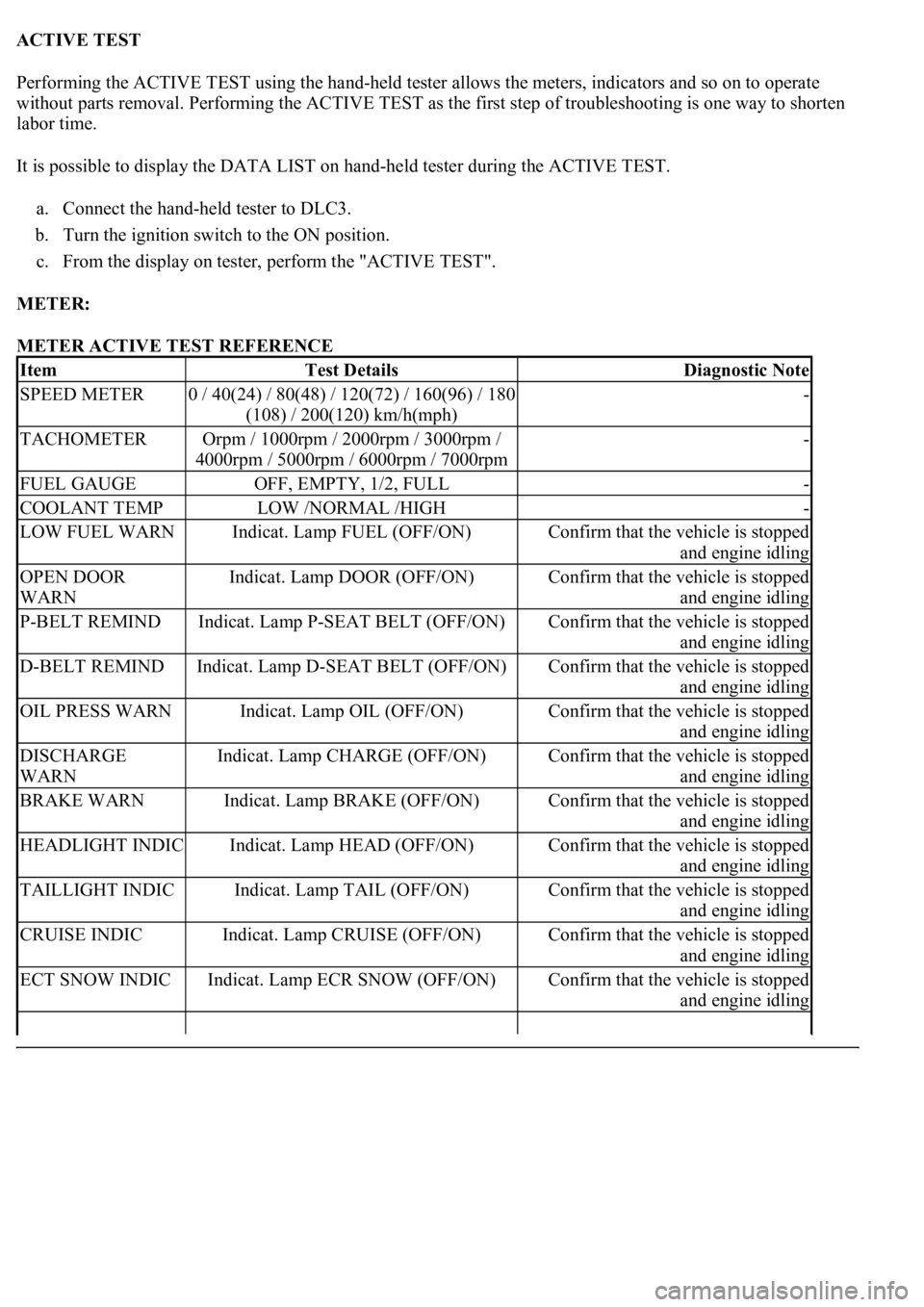
ACTIVE TEST
Performing the ACTIVE TEST using the hand-held tester allows the meters, indicators and so on to operate
without parts removal. Performing the ACTIVE TEST as the first step of troubleshooting is one way to shorten
labor time.
It is possible to display the DATA LIST on hand-held tester during the ACTIVE TEST.
a. Connect the hand-held tester to DLC3.
b. Turn the ignition switch to the ON position.
c. From the display on tester, perform the "ACTIVE TEST".
METER:
METER ACTIVE TEST REFERENCE
ItemTest DetailsDiagnostic Note
SPEED METER0 / 40(24) / 80(48) / 120(72) / 160(96) / 180
(108) / 200(120) km/h(mph)-
TACHOMETEROrpm / 1000rpm / 2000rpm / 3000rpm /
4000rpm / 5000rpm / 6000rpm / 7000rpm-
FUEL GAUGEOFF, EMPTY, 1/2, FULL-
COOLANT TEMPLOW /NORMAL /HIGH-
LOW FUEL WARNIndicat. Lamp FUEL (OFF/ON)Confirm that the vehicle is stopped
and engine idling
OPEN DOOR
WARNIndicat. Lamp DOOR (OFF/ON)Confirm that the vehicle is stopped
and engine idling
P-BELT REMINDIndicat. Lamp P-SEAT BELT (OFF/ON)Confirm that the vehicle is stopped
and engine idling
D-BELT REMINDIndicat. Lamp D-SEAT BELT (OFF/ON)Confirm that the vehicle is stopped
and engine idling
OIL PRESS WARNIndicat. Lamp OIL (OFF/ON)Confirm that the vehicle is stopped
and engine idling
DISCHARGE
WARNIndicat. Lamp CHARGE (OFF/ON)Confirm that the vehicle is stopped
and engine idling
BRAKE WARNIndicat. Lamp BRAKE (OFF/ON)Confirm that the vehicle is stopped
and engine idling
HEADLIGHT INDICIndicat. Lamp HEAD (OFF/ON)Confirm that the vehicle is stopped
and engine idling
TAILLIGHT INDICIndicat. Lamp TAIL (OFF/ON)Confirm that the vehicle is stopped
and engine idling
CRUISE INDICIndicat. Lamp CRUISE (OFF/ON)Confirm that the vehicle is stopped
and engine idling
ECT SNOW INDICIndicat. Lamp ECR SNOW (OFF/ON)Confirm that the vehicle is stopped
and engine idling
Page 1847 of 4500
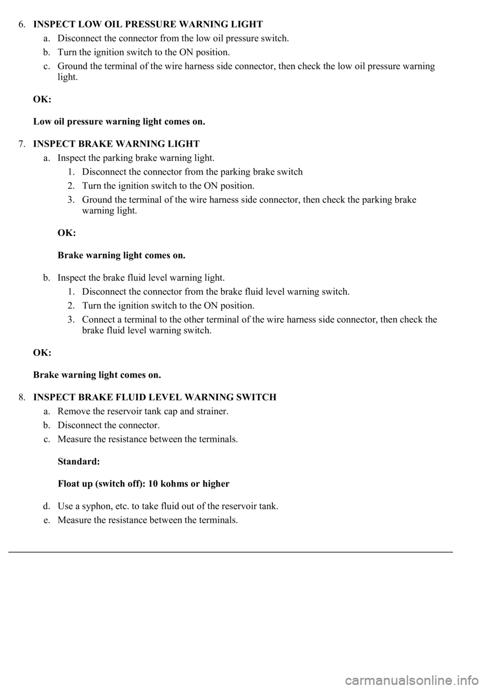
6.INSPECT LOW OIL PRESSURE WARNING LIGHT
a. Disconnect the connector from the low oil pressure switch.
b. Turn the ignition switch to the ON position.
c. Ground the terminal of the wire harness side connector, then check the low oil pressure warning
light.
OK:
Low oil pressure warning light comes on.
7.INSPECT BRAKE WARNING LIGHT
a. Inspect the parking brake warning light.
1. Disconnect the connector from the parking brake switch
2. Turn the ignition switch to the ON position.
3. Ground the terminal of the wire harness side connector, then check the parking brake
warning light.
OK:
Brake warning light comes on.
b. Inspect the brake fluid level warning light.
1. Disconnect the connector from the brake fluid level warning switch.
2. Turn the ignition switch to the ON position.
3. Connect a terminal to the other terminal of the wire harness side connector, then check the
brake fluid level warning switch.
OK:
Brake warning light comes on.
8.INSPECT BRAKE FLUID LEVEL WARNING SWITCH
a. Remove the reservoir tank cap and strainer.
b. Disconnect the connector.
c. Measure the resistance between the terminals.
Standard:
Float up (switch off): 10 kohms or higher
d. Use a syphon, etc. to take fluid out of the reservoir tank.
e. Measure the resistance between the terminals.