Page 718 of 4500

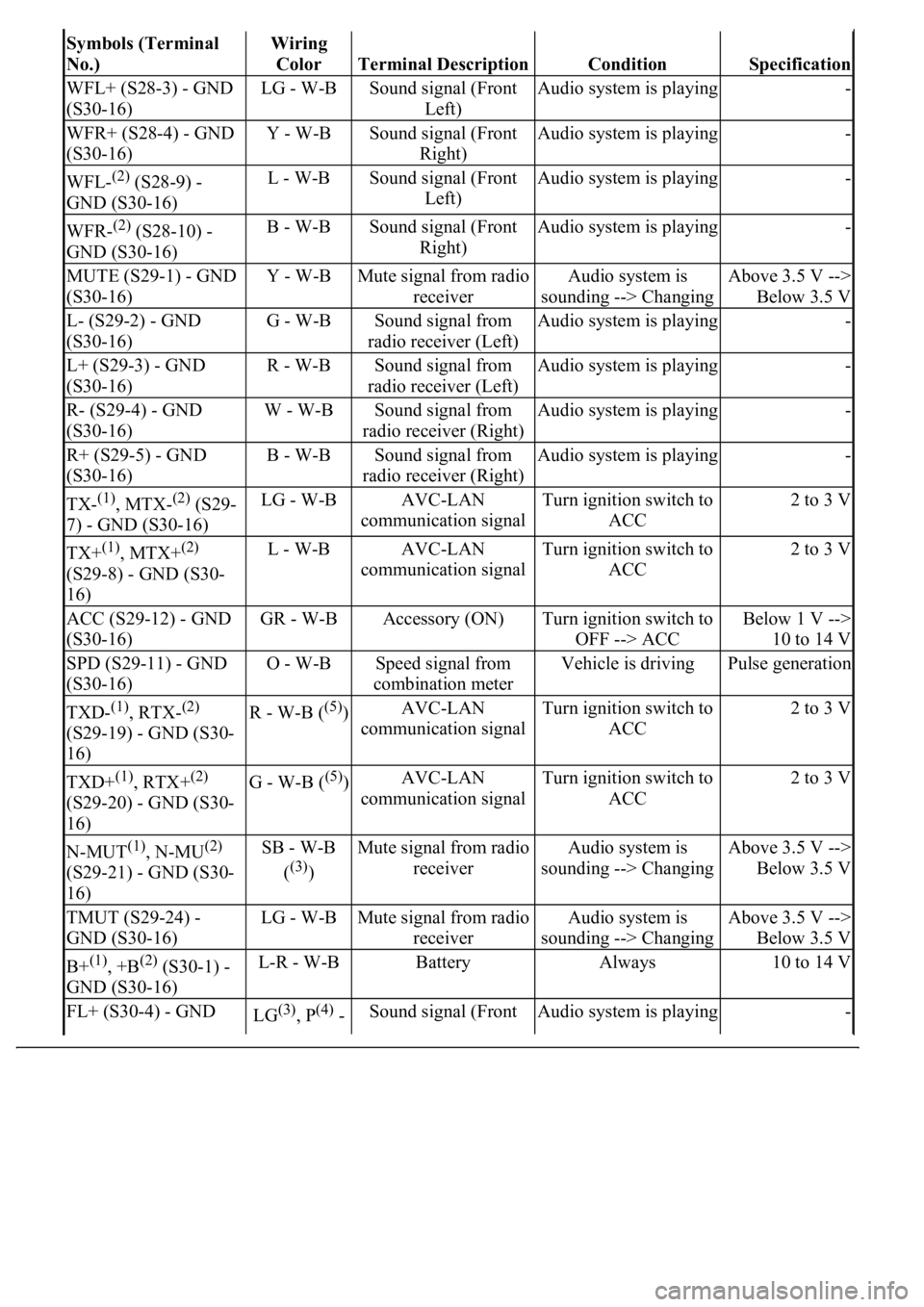
Symbols (Terminal
No.)Wiring
Color
Terminal DescriptionConditionSpecification
WFL+ (S28-3) - GND
(S30-16)LG - W-BSound signal (Front
Left)Audio system is playing-
WFR+ (S28-4) - GND
(S30-16)Y - W-BSound signal (Front
Right)Audio system is playing-
WFL-(2) (S28-9) -
GND (S30-16)L - W-BSound signal (Front
Left)Audio system is playing-
WFR-(2) (S28-10) -
GND (S30-16)B - W-BSound signal (Front
Right)Audio system is playing-
MUTE (S29-1) - GND
(S30-16)Y - W-BMute signal from radio
receiverAudio system is
sounding --> ChangingAbove 3.5 V -->
Below 3.5 V
L- (S29-2) - GND
(S30-16)G - W-BSound signal from
radio receiver (Left)Audio system is playing-
L+ (S29-3) - GND
(S30-16)R - W-BSound signal from
radio receiver (Left)Audio system is playing-
R- (S29-4) - GND
(S30-16)W - W-BSound signal from
radio receiver (Right)Audio system is playing-
R+ (S29-5) - GND
(S30-16)B - W-BSound signal from
radio receiver (Right)Audio system is playing-
TX-(1), MTX-(2) (S29-
7) - GND (S30-16)LG - W-BAVC-LAN
communication signalTurn ignition switch to
ACC2 to 3 V
TX+(1), MTX+(2)
(S29-8) - GND (S30-
16)L - W-BAVC-LAN
communication signalTurn ignition switch to
ACC2 to 3 V
ACC (S29-12) - GND
(S30-16)GR - W-BAccessory (ON)Turn ignition switch to
OFF --> ACCBelow 1 V -->
10 to 14 V
SPD (S29-11) - GND
(S30-16)O - W-BSpeed signal from
combination meterVehicle is drivingPulse generation
TXD-(1), RTX-(2)
(S29-19) - GND (S30-
16)R - W-B ((5))AVC-LAN
communication signalTurn ignition switch to
ACC2 to 3 V
TXD+(1), RTX+(2)
(S29-20) - GND (S30-
16)G - W-B ((5))AVC-LAN
communication signalTurn ignition switch to
ACC2 to 3 V
N-MUT(1), N-MU(2)
(S29-21) - GND (S30-
16)SB - W-B
(
(3))
Mute signal from radio
receiverAudio system is
sounding --> ChangingAbove 3.5 V -->
Below 3.5 V
TMUT (S29-24) -
GND (S30-16)LG - W-BMute signal from radio
receiverAudio system is
sounding --> ChangingAbove 3.5 V -->
Below 3.5 V
B+(1), +B(2) (S30-1) -
GND (S30-16)L-R - W-BBatteryAlways10 to 14 V
FL+ (S30-4) - GND LG(3), P(4) - Sound signal (Front Audio system is playing-
Page 720 of 4500

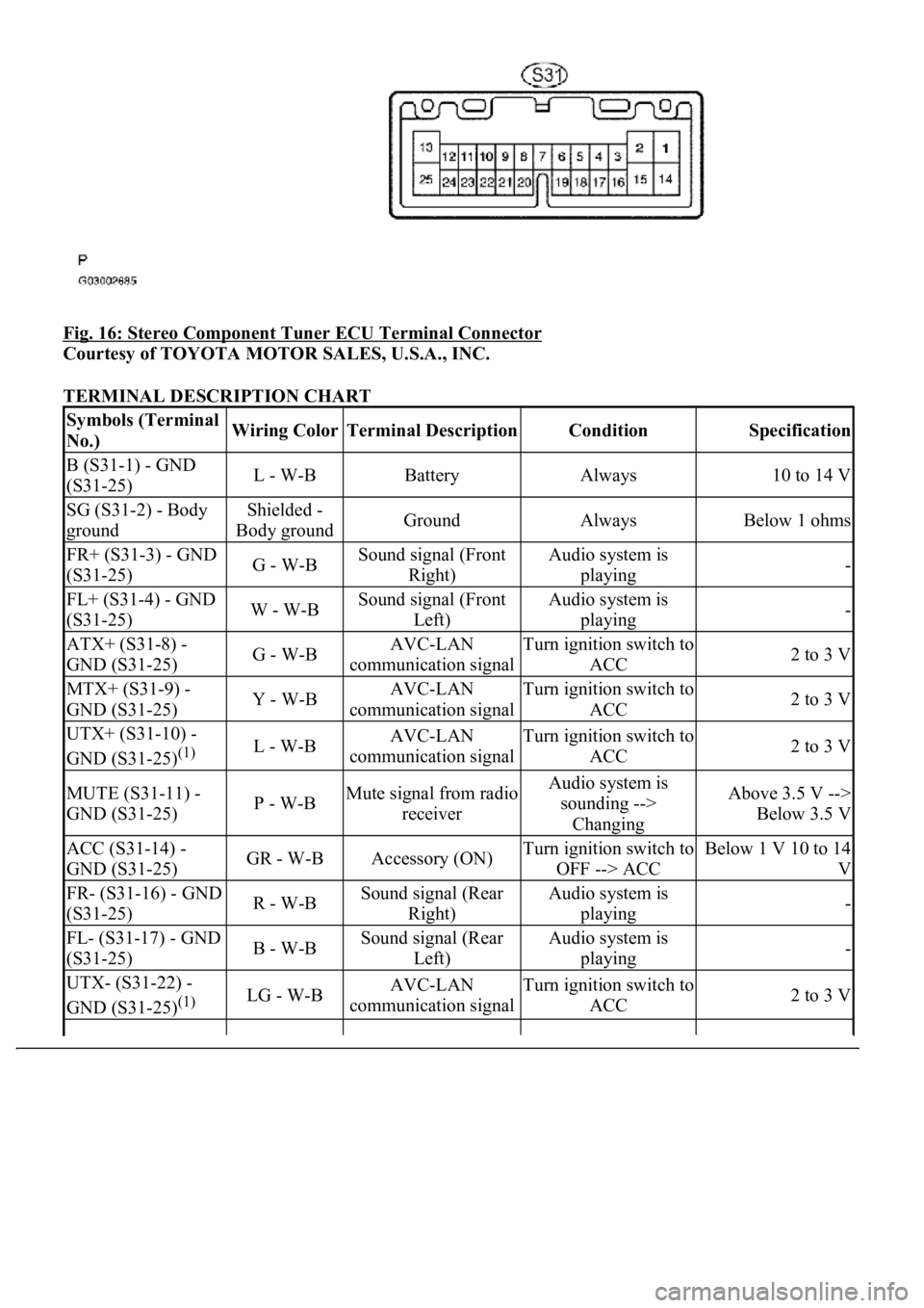
Fig. 16: Stereo Component Tuner ECU Terminal Connector
Courtesy of TOYOTA MOTOR SALES, U.S.A., INC.
TERMINAL DESCRIPTION CHART
Symbols (Terminal
No.)Wiring ColorTerminal DescriptionConditionSpecification
B (S31-1) - GND
(S31-25)L - W-BBatteryAlways10 to 14 V
SG (S31-2) - Body
groundShielded -
Body groundGroundAlwaysBelow 1 ohms
FR+ (S31-3) - GND
(S31-25)G - W-BSound signal (Front
Right)Audio system is
playing-
FL+ (S31-4) - GND
(S31-25)W - W-BSound signal (Front
Left)Audio system is
playing-
ATX+ (S31-8) -
GND (S31-25)G - W-BAVC-LAN
communication signalTurn ignition switch to
ACC2 to 3 V
MTX+ (S31-9) -
GND (S31-25)Y - W-BAVC-LAN
communication signalTurn ignition switch to
ACC2 to 3 V
UTX+ (S31-10) -
GND (S31-25)
(1)L - W-BAVC-LAN
communication signalTurn ignition switch to
ACC2 to 3 V
MUTE (S31-11) -
GND (S31-25)P - W-BMute signal from radio
receiverAudio system is
sounding -->
ChangingAbove 3.5 V -->
Below 3.5 V
ACC (S31-14) -
GND (S31-25)GR - W-BAccessory (ON)Turn ignition switch to
OFF --> ACCBelow 1 V 10 to 14
V
FR- (S31-16) - GND
(S31-25)R - W-BSound signal (Rear
Right)Audio system is
playing-
FL- (S31-17) - GND
(S31-25)B - W-BSound signal (Rear
Left)Audio system is
playing-
UTX- (S31-22) -
GND (S31-25)
(1)LG - W-BAVC-LAN
communication signalTurn ignition switch to
ACC2 to 3 V
Page 721 of 4500
4.AUDIO AND REAR A/C CONTROL SW
Fig. 17: Audio And Rear A/C Control SW ECU Terminal Connector
Courtesy of TOYOTA MOTOR SALES, U.S.A., INC.
TERMINAL DESCRIPTION CHART
ATX- (S31-20) -
GND (S31-25)R - W-BAVC-LAN
communication signalTurn ignition switch to
ACC2 to 3 V
MTX- (S31-21) -
GND (S31-25)B - W-BAVC-LAN
communication signalTurn ignition switch to
ACC2 to 3 V
GND (S31-25) -
Body groundW-B - Body
groundGroundAlwaysBelow 1 ohms
(1)w/ LEXUS Navigation System
Symbols (Terminal
No.)Wiring
ColorTerminal DescriptionConditionSpecification
Page 722 of 4500

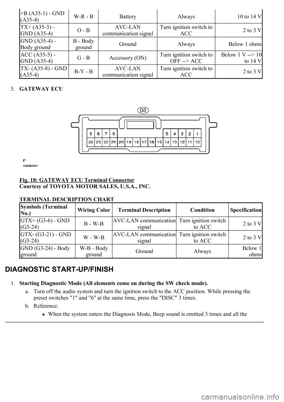
5.GATEWAY ECU
Fig. 18: GATEWAY ECU Terminal Connector
Courtesy of TOYOTA MOTOR SALES, U.S.A., INC.
TERMINAL DESCRIPTION CHART
1.Starting Diagnostic Mode (All elements come on during the SW check mode).
a. Turn off the audio system and turn the ignition switch to the ACC position. While pressing the
preset switches "1" and "6" at the same time, press the "DISC" 3 times.
b. Reference:
<003a004b0048005100030057004b004800030056005c0056005700480050000300480051005700480055005600030057004b004800030027004c0044004a005100520056004c005600030030005200470048000f0003002500480048005300030056005200
58005100470003004c0056000300480050004c005700570048[d 3 times and all the
+B (A35-1) - GND
(A35-4)W-R - BBatteryAlways10 to 14 V
TX+ (A35-3) -
GND (A35-4)O - BAVC-LAN
communication signalTurn ignition switch to
ACC2 to 3 V
GND (A35-4) -
Body groundB - Body
groundGroundAlwaysBelow 1 ohms
ACC (A35-5) -
GND (A35-4)G - BAccessory (ON)Turn ignition switch to
OFF --> ACCBelow 1 V --> 10
to 14 V
TX- (A35-8) - GND
(A35-4)B-Y - BAVC-LAN
communication signalTurn ignition switch to
ACC2 to 3 V
Symbols (Terminal
No.)Wiring ColorTerminal DescriptionConditionSpecification
GTX+ (G3-6) - GND
(G3-24)B - W-BAVC-LAN communication
signalTurn ignition switch
to ACC2 to 3 V
GTX- (G3-21) - GND
(G3-24)W - W-BAVC-LAN communication
signalTurn ignition switch
to ACC2 to 3 V
GND (G3-24) - Body
groundW-B - Body
groundGroundAlwaysBelow 1
ohms
Page 724 of 4500
3.Finishing Diagnostic Mode.
a. Press the "DISC" for 2 seconds or more, or turn the ignition switch off.
HINT:
Illustrations may differ from the actual vehicle depending on the device settings and options. Therefore, some
detailed areas may not be shown exactly the same as on the actual vehicle.
1.Start the diagnostic mode (SEE DIAGNOSTIC START
-UP/FINISH ).
2.Read the system check result.
1. Press the "SEEK TRACK" switch to see the check result of each component.
2. The component device code (physical address) is displayed first, and then the check result follows.
HINT:
If all check results are "good" the system judges that no DTC exists.
device comprising AVC-LAN
Page 729 of 4500

1.DATA LIST
HINT:
By the DATA LIST displayed on the hand-held tester, you can read the value of the switch, sensor,
actuator and so on without removing any parts. Reading the DATA LIST as the first step in
troubleshooting is one of the methods to shorten labor time.
a. Connect the hand-held tester to the DLC3.
b. Turn the ignition switch to the ON position.
c. According to the display on the tester, read the "DATA LIST".
SPAD:
Fig. 24: Spad Item Chart
Courtesy of TOYOTA MOTOR SALES, U.S.A., INC.
DIAGNOSTIC TROUBLE CODE CHART
HINT:
Titles for each unit are stated in the followin
g order: parts name (physical address) [Name indicated by DTC]
TermsDescription
Physical address3-digit, hexadecimal code assigned to all components connected to the AVC-LAN.
Individual symbols are specified based on function. Units whose names are unknown or
relevant units are displayed with physical addresses.
Logical address2-digit, hexadecimal code assigned to all the functions in the AVC-LAN system.
Page 730 of 4500
1.RADIO RECEIVER ASSY (Physical address: 190) [AUDIO H/U]
a. Logical address: 01 (Communication control)
HINT:
Methods used to verify the cause of the problem are listed in order of probability in the verification
column.
Fig. 25: DTC Detecting Condition Chart
Courtesy of TOYOTA MOTOR SALES, U.S.A., INC.
HINT:
*1: Even if no failure is detected, a trouble code may be recorded depending on the battery
condition or engine start voltage.
*2: If the power connector is disconnected after the engine starts, this code is recorded after
180 seconds.
*3: This code may be stored if the ignition key is turned again after the engine starts.
Page 731 of 4500
*4: This code may be stored if the ignition key is held in the START position for one minute
or more before returning to the ON position.
*5: If the device is reported as not existing during verification, check the power source circuit
and AVC-LAN circuit for the device.
b. Logical address: 62 (CD): 63 (CD changer)
HINT:
Methods used to verify the cause of the problem are listed in order of probability in the verification
column.