Page 838 of 4500

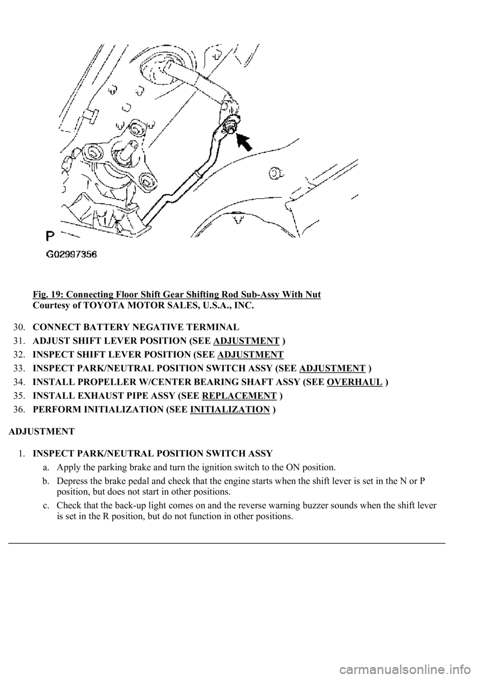
<0029004c004a001100030014001c001d00030026005200510051004800460057004c0051004a00030029004f00520052005500030036004b004c004900570003002a00480044005500030036004b004c00490057004c0051004a0003003500520047000300
3600580045[-Assy With Nut
Courtesy of TOYOTA MOTOR SALES, U.S.A., INC.
30.CONNECT BATTERY NEGATIVE TERMINAL
31.ADJUST SHIFT LEVER POSITION (SEE ADJUSTMENT
)
32.INSPECT SHIFT LEVER POSITION (SEE ADJUSTMENT
33.INSPECT PARK/NEUTRAL POSITION SWITCH ASSY (SEE ADJUSTMENT
)
34.INSTALL PROPELLER W/CENTER BEARING SHAFT ASSY (SEE OVERHAUL
)
35.INSTALL EXHAUST PIPE ASSY (SEE REPLACEMENT
)
36.PERFORM INITIALIZATION (SEE INITIALIZATION
)
ADJUSTMENT
1.INSPECT PARK/NEUTRAL POSITION SWITCH ASSY
a. Apply the parking brake and turn the ignition switch to the ON position.
b. Depress the brake pedal and check that the engine starts when the shift lever is set in the N or P
position, but does not start in other positions.
c. Check that the back-up light comes on and the reverse warning buzzer sounds when the shift lever
is set in the R position, but do not function in other positions.
Page 921 of 4500
Fig. 98: Staking Nut
Courtesy of TOYOTA MOTOR SALES, U.S.A., INC.
24.INSTALL PROPELLER W/CENTER BEARING SHAFT ASSY (SEE OVERHAUL
)
25.FULLY TIGHTEN CENTER SUPPORT BEARING ASSY NO.1 (SEE OVERHAUL
)
26.INSTALL EXHAUST PIPE ASSY (SEE REPLACEMENT
)
27.ADD AUTOMATIC TRANSMISSION FLUID (SEE ADJUSTMENT
)
Fluid type: ATF WS
Capacity: 1.7 liters (1.8 US qts, 1.5 Imp.qts)
ON-VEHICLE INSPECTION
1.CHECK SHIFT LOCK OPERATION
a. Move the shift lever to the P position.
b. Turn the ignition switch to the LOCK position.
c. Check that the shift lever cannot be moved to any position other than P.
d. Turn the ignition switch to the ON position, depress the brake pedal and check that the shift lever
can be moved to another position.
Page 922 of 4500

If the operation cannot be done as specified, inspect the shift lock control unit.
2.CHECK SHIFT LOCK RELEASE BUTTON OPERATION
a. Using a small screwdriver, remove the shift lock release cover.
b. When operating the shift lever with the shift lock release button pressed, check that the lever can be
moved to any position other than P.
If the operation cannot be done as specified, check the shift lever assy installation condition.
3.CHECK KEY INTERLOCK OPERATION
a. Turn the ignition switch to the ON position.
b. Depress the brake pedal and adjust the shift lever to any position other than P.
c. Check that the ignition key cannot be turned to the LOCK position.
d. Move the shift lever to the P position, turn the ignition key to the LOCK position and check that the
ignition key can be removed.
If the operation cannot be done as specified, inspect the shift lock control unit.
4.INSPECT SHIFT LOCK CONTROL UNIT ASSEMBLY
a. Measure the voltage according to the value(s) in the table below.
HINT:
Do not disconnect the shift lock control unit assembl
y connector.
Page 960 of 4500
Fig. 135: Installing Floor Shift Gear Shifting Rod Sub-Assy With Nut
Courtesy of TOYOTA MOTOR SALES, U.S.A., INC.
51.CONNECT BATTERY NEGATIVE TERMINAL
52.ADJUST SHIFT LEVER POSITION (SEE ADJUSTMENT
)
53.INSPECT SHIFT LEVER POSITION (SEE ADJUSTMENT
)
54.PERFORM INITIALIZATION (SEE INITIALIZATION
)
ADJUSTMENT
1.INSPECT SHIFT LEVER POSITION
a. When shifting from the P to R position with the ignition switch on and brake pedal depressed, make
sure that the shift lever moves smoothly and moves correctly into position.
b. Start the engine and make sure that the vehicle moves forward when shifting from the N to D
position and moves rearward when shifting to the R position.
If operation cannot be done as specified, inspect the park/neutral position switch assy and check the shift
lever assy installation condition.
2.ADJUST SHIFT LEVER POSITION
a. Remove the nut and disconnect the shiftin
g rod from the connecting rod swivel.
Page 970 of 4500
Fig. 7: Connecting Hand-Held Tester To DLC3
Courtesy of TOYOTA MOTOR SALES, U.S.A., INC.
b. Connect the hand-held tester to the DLC3, then turn the ignition switch to the ON position.
c. Turn the hand-held tester power on and select "AIR BLEEDING" on the screen.
d. Perform air bleeding according to "Step 1: Increase" on the hand-held tester display.
Page 977 of 4500
Fig. 14: Depressing Brake Pedal Several Times And Loosen Bleeder Plug
Courtesy of TOYOTA MOTOR SALES, U.S.A., INC.
3. When fluid stops coming out, tighten the bleeder plug, then release the brake pedal.
4. Repeat (2) and (3) until all the air in the fluid is completely bled out.
5. Tighten the bleeder plug completely.
Torque: 11 N.m (110 kgf.cm, 8 ft.lbf)
6. Repeat the above procedures for each wheels to bleed the air out of the brake line.
SST 09992-00242, 09992-00350
h. Finish "AIR BLEEDING" on the hand-held tester and turn off the power.
i. Disconnect the hand-held tester from the DLC3.
j. Turn the ignition switch off.
5.CHECK FLUID LEVEL IN RESERVOIR
a. Check the fluid level and add fluid, if necessar
y.
Page 1212 of 4500
Fig. 16: Identifying DCL3 Connector Terminals
Courtesy of TOYOTA MOTOR SALES, U.S.A., INC.
2.DLC3
a. Measure the resistance according to the value (s) in the table below.
Standard:
ECM CONNECTOR TERMINALS RESISTANCE
TerminalsWiring ColorConditionSpecified Condition
D1-6 (CANH) - D1-14 (CANL)B - WIgnition Switch OFF54 to 69 ohms
D1-6 (CANH) - D1-4 (CG)B - W-BIgnition Switch OFF1 kohms or more
D1-14 (CANL) - D1-4 (CG)W - W-BIgnition Switch OFF1 kohms or more
D1-6 (CANH) - D1-16 (BAT)B - BIgnition Switch OFF1 Mohms or more
D1-14 (CANL) - D1-16 (BAT)W - BIgnition Switch OFF1 Mohms or more
Page 1213 of 4500
Fig. 17: Identifying Skid Control ECU Connector Terminals
Courtesy of TOYOTA MOTOR SALES, U.S.A., INC.
3.SKID CONTROL ECU
a. Measure the resistance according to the value (s) in the table below.
Standard:
SKID CONTROL ECU CONNECTOR TERMINALS RESISTANCE
TerminalsWiring ColorConditionSpecified Condition
S42-11 (CANH) - S42-25 (CANL)BR - YIgnition Switch OFF54 to 69 ohms
S42-11 (CANH) - S42-32 (GND1)BR - W-BIgnition Switch OFF1 kohms or more
S42-25 (CANL) - S42-32 (GND1)Y - W-BIgnition Switch OFF1 kohms or more
S42-11 (CANH) - S42-31 (+BS)BR - BIgnition Switch OFF1 Mohms or more
S42-25 (CANL) - S42-31 (+BS)Y - BIgnition Switch OFF1 Mohms or more