Page 1072 of 4378
22. Disconnect the engine oil pressure sender electrical connector.
23. Remove the pin-
type retainer.
24. Disconnect the crankshaft position (CKP) sensor electrical connector.
25. Remove the engine wiring harness.
26. Remove the stud bolt. �K�l�j . 7 �b�a
212003 Mustang Workshop Manual
17. 11. 2011file:///C:/Ford/2000 - 2004/tsocache/SHEF_4464/S3B~us~en~ ...
Page 1081 of 4378
56. Remove the engine dynamic balance shaft.
�zRemove the bolts.
�z Remove the balance shaft driven gear, thrust plate and engine dynamic balance shaft as
an assembly.
57. Remove the valve tappets. 1. Remove the bolts.
2. Remove the tappet guide plates and retainers.
3. Remove the valve tappets.
58. Remove the engine balance shaft drive gear. 1. Remove the camshaft keyway.
2. Remove the gear. �K�l�j . 16 �b�a
212003 Mustang Workshop Manual
17. 11. 2011file:///C:/Ford/2000 - 2004/tsocache/SHEF_4464/S3B~us~en~ ...
Page 1082 of 4378
59. Remove the camshaft.
1. Remove the bolts.
2. Remove the camshaft thrust plate.
3. Remove the spacer.
4. Remove the camshaft.
60. Remove the bearing covers. 1. Remove the engine dynamic balance shaft bearing cover.
2. Remove the camshaft bearing cover.
61. Remove the oil pump screen cover and tube. �K�l�j . 17 �b�a
212003 Mustang Workshop Manual
17. 11. 2011file:///C:/Ford/2000 - 2004/tsocache/SHEF_4464/S3B~us~en~ ...
Page 1083 of 4378

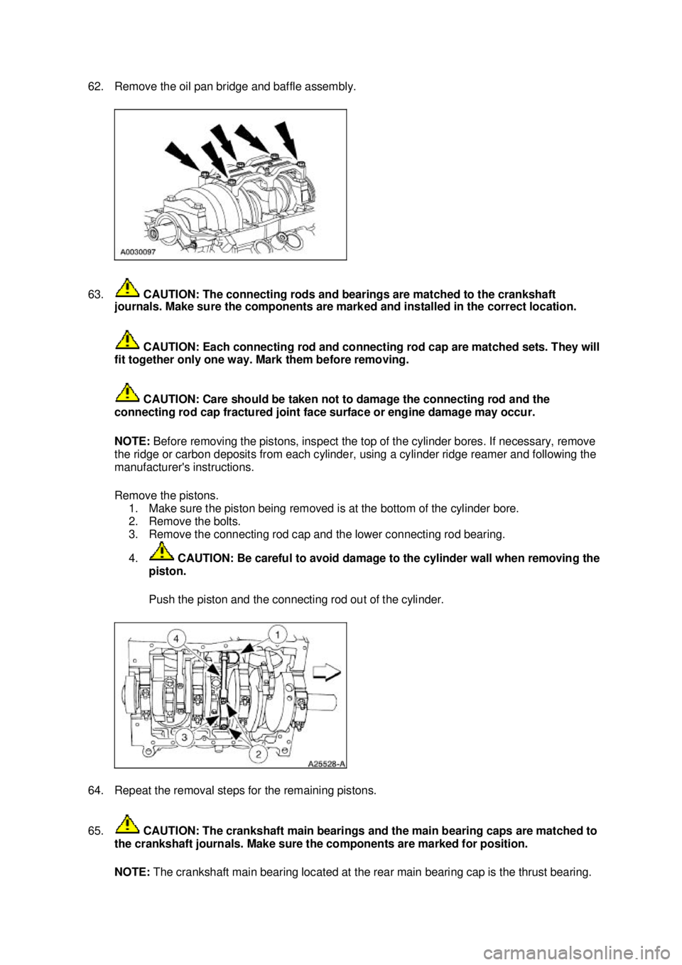
62. Remove the oil pan bridge and baffle assembly.
63.
CAUTION: The connecting rods and bearings are matched to the crankshaft
journals. Make sure the components are marked and installed in the correct location.
CAUTION: Each connecting rod and connecting rod cap are matched sets. They will
fit together only one way. Mark them before removing.
CAUTION: Care should be taken not to damage the connecting rod and the
connecting rod cap fractured joint face surface or engine damage may occur.
NOTE: Before removing the pistons, inspect the top of the cylinder bores. If necessary, remove
the ridge or carbon deposits from each cylinder, using a cylinder ridge reamer and following the
manufacturer's instructions.
Remove the pistons. 1. Make sure the piston being removed is at the bottom of the cylinder bore.
2. Remove the bolts.
3. Remove the connecting rod cap and the lower connecting rod bearing.
4. CAUTION: Be careful to avoid damage to the cylinder wall when removing the
piston.
Push the piston and the connecting rod out of the cylinder.
64. Repeat the removal steps for the remaining pistons.
65. CAUTION: The crankshaft main bearings and the main bearing caps are matched to
the crankshaft journals. Make sure the components are marked for position. NOTE: The crankshaft main bearing located at the rear main bearing cap is the thrust bearing. �K�l�j . 18 �b�a
212003 Mustang Workshop Manual
17. 11. 2011file:///C:/Ford/2000 - 2004/tsocache/SHEF_4464/S3B~us~en~ ...
Page 1085 of 4378
70. Using the camshaft bearing service set, remove the engine dynamic balance shaft bearings.
71. If equipped, remove the engine block heater. For additional information, refer to
Section 303 -
03A .
72. NOTE: For cleaning purposes, the plugs should be removed.
If necessary, remove the following: 1. the cylinder block dowels.
2. the oil gallery plugs.
3. the water jacket plugs. �K�l�j . 20 �b�a
212003 Mustang Workshop Manual
17. 11. 2011file:///C:/Ford/2000 - 2004/tsocache/SHEF_4464/S3B~us~en~ ...
Page 1087 of 4378
DISASSEMBLY AND ASSEMBLY OF SUBASSEMBLIES
Cylinder Head
Disassembly and Assembly
CAUTION: If the components are to be reinstalled, they must be installed in the same
position. Mark the components removed for location.
1. Remove the spark plugs (12405) if necessary.
2. Using the special tool, compress the valve springs (6513).
3. Remove the following: 1. The valve spring retainer key (6518).
2. The valve spring retainers (6514).
3. The valve springs (6513).
4. The valve stem seals and seats (6A517).
SECTION 303-
01A: Engine — 3.8L 2003 Mustang Workshop Manual Special Tool(s)
Compressor, Valve Spring
303-
163 (T81P-6513- A)
Material Item Specification
SAE 5W-
20 Premium Synthetic
Blend Motor Oil
XO- 5W20-QSP or equivalent WSS-
M2C153-
H �K�l�j . 1 �b�a
22003 Mustang Workshop Manual
17. 11. 2011file:///C:/Ford/2000 - 2004/tsocache/SHEF_4464/S3B~us~en~ ...
Page 1088 of 4378
4. Inspect the components. For additional information, refer to
Section 303 - 00 .
5. CAUTION: Lubricate the parts with clean engine oil before installing.
To assemble, reverse the disassembly procedure. �K�l�j . 2 �b�a
22003 Mustang Workshop Manual
17. 11. 2011file:///C:/Ford/2000 - 2004/tsocache/SHEF_4464/S3B~us~en~ ...
Page 1089 of 4378
DISASSEMBLY AND ASSEMBLY OF SUBASSEMBLIES
Piston
Disassembly
1. Using the special tool, press the piston pin out from the connecting rod and piston assembly.
2. Remove the connecting rod from the piston.
3. Clean and inspect the connecting rod and piston. For additional information, refer to Section 303 - 00 .
Assembly SECTION 303-
01A: Engine — 3.8L 2003 Mustang Workshop Manual Special Tool(s)
Piston Pin Tool or equivalent
303-
D034 (D81L- 6135-A)
Material Item Specification
SAE 5W-
20 Premium Synthetic
Blend Motor Oil
XO- 5W20-QSP or equivalent WSS-
M2C153-
H �K�l�j . 1 �b�a
32003 Mustang Workshop Manual
17. 11. 2011file:///C:/Ford/2000 - 2004/tsocache/SHEF_4464/S3B~us~en~ ...